Cigar lighter JEEP GRAND CHEROKEE 2003 WJ / 2.G User Guide
[x] Cancel search | Manufacturer: JEEP, Model Year: 2003, Model line: GRAND CHEROKEE, Model: JEEP GRAND CHEROKEE 2003 WJ / 2.GPages: 2199, PDF Size: 76.01 MB
Page 1107 of 2199
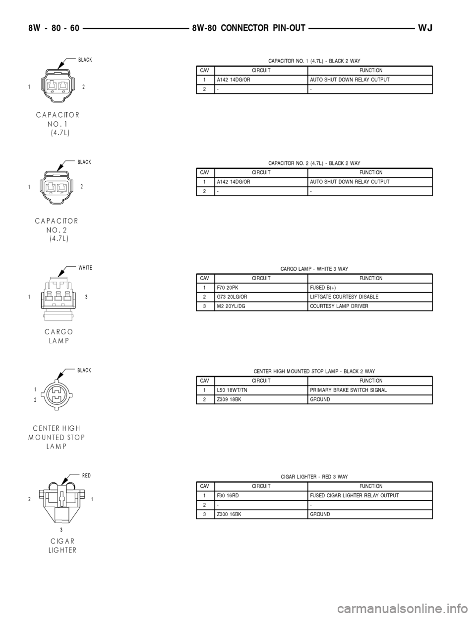
CAPACITOR NO. 1 (4.7L) - BLACK 2 WAY
CAV CIRCUIT FUNCTION
1 A142 14DG/OR AUTO SHUT DOWN RELAY OUTPUT
2- -
CAPACITOR NO. 2 (4.7L) - BLACK 2 WAY
CAV CIRCUIT FUNCTION
1 A142 14DG/OR AUTO SHUT DOWN RELAY OUTPUT
2- -
CARGO LAMP - WHITE 3 WAY
CAV CIRCUIT FUNCTION
1 F70 20PK FUSED B(+)
2 G73 20LG/OR LIFTGATE COURTESY DISABLE
3 M2 20YL/DG COURTESY LAMP DRIVER
CENTER HIGH MOUNTED STOP LAMP - BLACK 2 WAY
CAV CIRCUIT FUNCTION
1 L50 18WT/TN PRIMARY BRAKE SWITCH SIGNAL
2 Z309 18BK GROUND
CIGAR LIGHTER - RED 3 WAY
CAV CIRCUIT FUNCTION
1 F30 16RD FUSED CIGAR LIGHTER RELAY OUTPUT
2- -
3 Z300 16BK GROUND
8W - 80 - 60 8W-80 CONNECTOR PIN-OUTWJ
Page 1134 of 2199
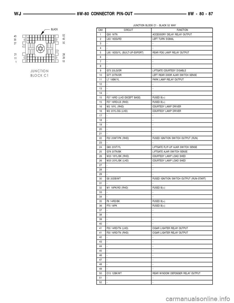
JUNCTION BLOCK C1 - BLACK 52 WAY
CAV CIRCUIT FUNCTION
1 Q30 16TN ACCESSORY DELAY RELAY OUTPUT
2 L63 18DG/RD LEFT TURN SIGNAL
3- -
4- -
5 L95 18DG/YL (BUILT-UP-EXPORT) REAR FOG LAMP RELAY OUTPUT
6- -
7- -
8- -
9 G73 20LG/OR LIFTGATE COURTESY DISABLE
10 G77 20TN/OR LEFT REAR DOOR AJAR SWITCH SENSE
11 L7 18BK/YL PARK LAMP RELAY OUTPUT
12 - -
13 - -
14 - -
15 F37 16RD (LHD EXCEPT BASE) FUSED B(+)
15 F37 16RD/LB (RHD) FUSED B(+)
16 M2 18YL (RHD) COURTESY LAMP DRIVER
16 M2 20YL/DG (LHD) COURTESY LAMP DRIVER
17 - -
18 - -
19 - -
20 - -
21 - -
22 F22 20WT/PK (RHD) FUSED IGNITION SWITCH OUTPUT (RUN)
23 - -
24 G80 20VT/YL LIFTGATE FLIP-UP AJAR SWITCH SENSE
25 G78 20TN/BK LIFTGATE AJAR SWITCH SENSE
26 M20 18YL/BK (RHD) COURTESY LAMP LOAD SHED
26 M20 20YL/BK (LHD) COURTESY LAMP LOAD SHED
27 - -
28 - -
29 - -
30 G5 20DB/WT FUSED IGNITION SWITCH OUTPUT (RUN-START)
31 - -
32 M1 18PK/RD (RHD) FUSED B(+)
33 - -
34 - -
35 F9 14RD/BK FUSED B(+)
36 F70 18PK FUSED B(+)
37 - -
38 - -
39 - -
40 - -
41 F30 14RD/TN (LHD) CIGAR LIGHTER RELAY OUTPUT
41 F30 16RD/TN (RHD) CIGAR LIGHTER RELAY OUTPUT
42 - -
43 - -
44 - -
45 - -
46 - -
47 - -
48 - -
49 - -
50 C15 12BK/WT REAR WINDOW DEFOGGER RELAY OUTPUT
51 - -
52 - -
WJ8W-80 CONNECTOR PIN-OUT 8W - 80 - 87
Page 1137 of 2199
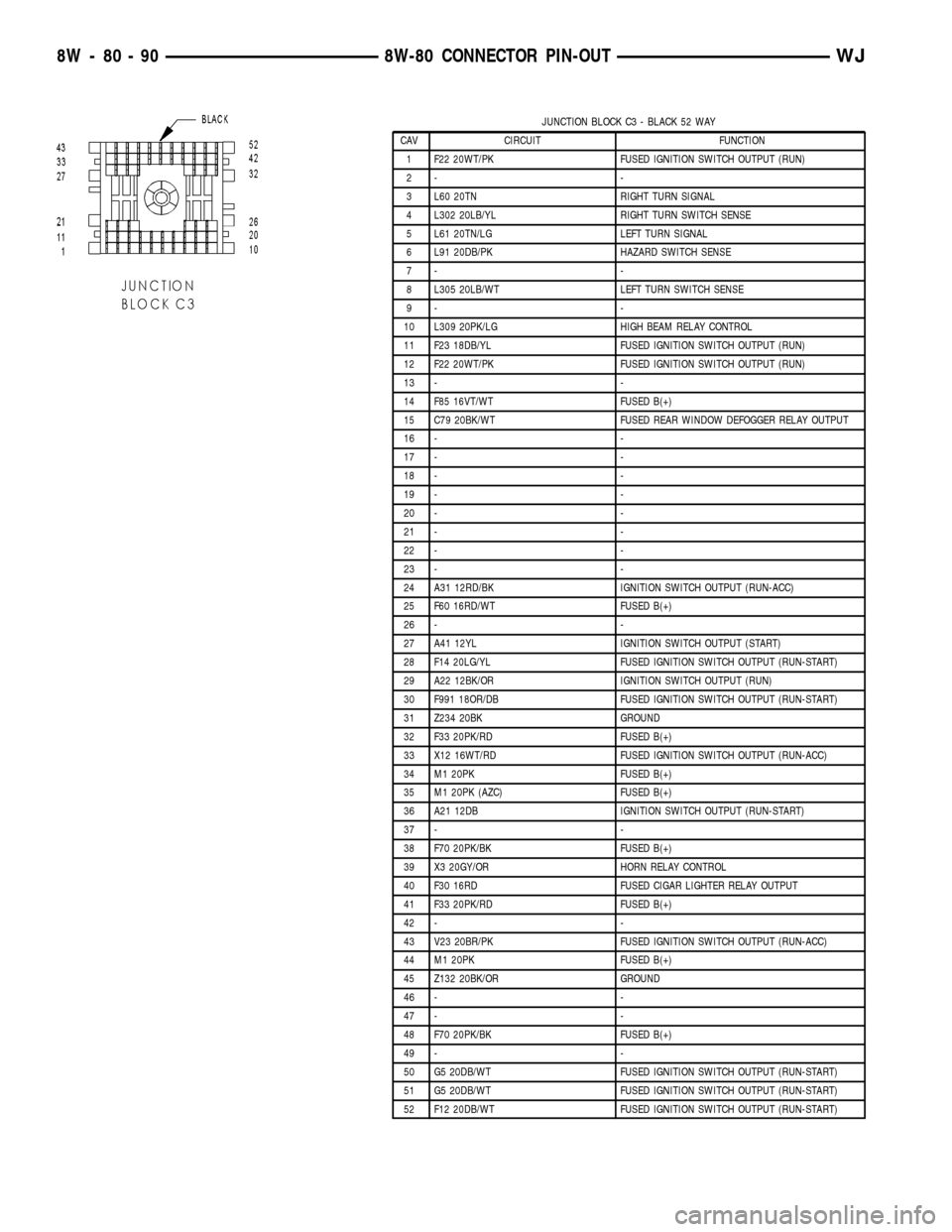
JUNCTION BLOCK C3 - BLACK 52 WAY
CAV CIRCUIT FUNCTION
1 F22 20WT/PK FUSED IGNITION SWITCH OUTPUT (RUN)
2- -
3 L60 20TN RIGHT TURN SIGNAL
4 L302 20LB/YL RIGHT TURN SWITCH SENSE
5 L61 20TN/LG LEFT TURN SIGNAL
6 L91 20DB/PK HAZARD SWITCH SENSE
7- -
8 L305 20LB/WT LEFT TURN SWITCH SENSE
9- -
10 L309 20PK/LG HIGH BEAM RELAY CONTROL
11 F23 18DB/YL FUSED IGNITION SWITCH OUTPUT (RUN)
12 F22 20WT/PK FUSED IGNITION SWITCH OUTPUT (RUN)
13 - -
14 F85 16VT/WT FUSED B(+)
15 C79 20BK/WT FUSED REAR WINDOW DEFOGGER RELAY OUTPUT
16 - -
17 - -
18 - -
19 - -
20 - -
21 - -
22 - -
23 - -
24 A31 12RD/BK IGNITION SWITCH OUTPUT (RUN-ACC)
25 F60 16RD/WT FUSED B(+)
26 - -
27 A41 12YL IGNITION SWITCH OUTPUT (START)
28 F14 20LG/YL FUSED IGNITION SWITCH OUTPUT (RUN-START)
29 A22 12BK/OR IGNITION SWITCH OUTPUT (RUN)
30 F991 18OR/DB FUSED IGNITION SWITCH OUTPUT (RUN-START)
31 Z234 20BK GROUND
32 F33 20PK/RD FUSED B(+)
33 X12 16WT/RD FUSED IGNITION SWITCH OUTPUT (RUN-ACC)
34 M1 20PK FUSED B(+)
35 M1 20PK (AZC) FUSED B(+)
36 A21 12DB IGNITION SWITCH OUTPUT (RUN-START)
37 - -
38 F70 20PK/BK FUSED B(+)
39 X3 20GY/OR HORN RELAY CONTROL
40 F30 16RD FUSED CIGAR LIGHTER RELAY OUTPUT
41 F33 20PK/RD FUSED B(+)
42 - -
43 V23 20BR/PK FUSED IGNITION SWITCH OUTPUT (RUN-ACC)
44 M1 20PK FUSED B(+)
45 Z132 20BK/OR GROUND
46 - -
47 - -
48 F70 20PK/BK FUSED B(+)
49 - -
50 G5 20DB/WT FUSED IGNITION SWITCH OUTPUT (RUN-START)
51 G5 20DB/WT FUSED IGNITION SWITCH OUTPUT (RUN-START)
52 F12 20DB/WT FUSED IGNITION SWITCH OUTPUT (RUN-START)
8W - 80 - 90 8W-80 CONNECTOR PIN-OUTWJ
Page 1169 of 2199
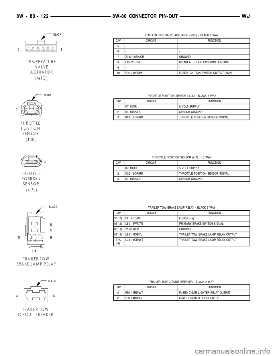
TEMPERATURE VALVE ACTUATOR (MTC) - BLACK 6 WAY
CAV CIRCUIT FUNCTION
5- -
6- -
7 Z132 20BK/OR GROUND
8 C67 20RD/LB BLEND AIR DOOR POSITION CONTROL
9- -
10 F22 20WT/PK FUSED IGNITION SWITCH OUTPUT (RUN)
THROTTLE POSITION SENSOR (4.0L) - BLACK 3 WAY
CAV CIRCUIT FUNCTION
1 K7 18OR 5 VOLT SUPPLY
2 K4 18BK/LB SENSOR GROUND
3 K22 18OR/RD THROTTLE POSITION SENSOR SIGNAL
THROTTLE POSITION SENSOR (4.7L)-3WAY
CAV CIRCUIT FUNCTION
1 K7 18OR 5 VOLT SUPPLY
2 K22 18OR/RD THROTTLE POSITION SENSOR SIGNAL
3 K4 18BK/LB SENSOR GROUND
TRAILER TOW BRAKE LAMP RELAY - BLACK 5 WAY
CAV CIRCUIT FUNCTION
30 (3) F9 14RD/BK FUSED B(+)
85 (2) L50 18WT/TN PRIMARY BRAKE SWITCH SIGNAL
86 (1) Z150 18BK GROUND
87 (5) L95 14DG/YL TRAILER TOW BRAKE LAMP RELAY OUTPUT
87A
(4)L94 14OR/WT TRAILER TOW BRAKE LAMP RELAY OUTPUT
TRAILER TOW CIRCUIT BREAKER - BLACK 2 WAY
CAV CIRCUIT FUNCTION
A F30 14RD/WT FUSED CIGAR LIGHTER RELAY OUTPUT
B F30 14RD/TN CIGAR LIGHTER RELAY OUTPUT
8W - 80 - 122 8W-80 CONNECTOR PIN-OUTWJ
Page 1170 of 2199
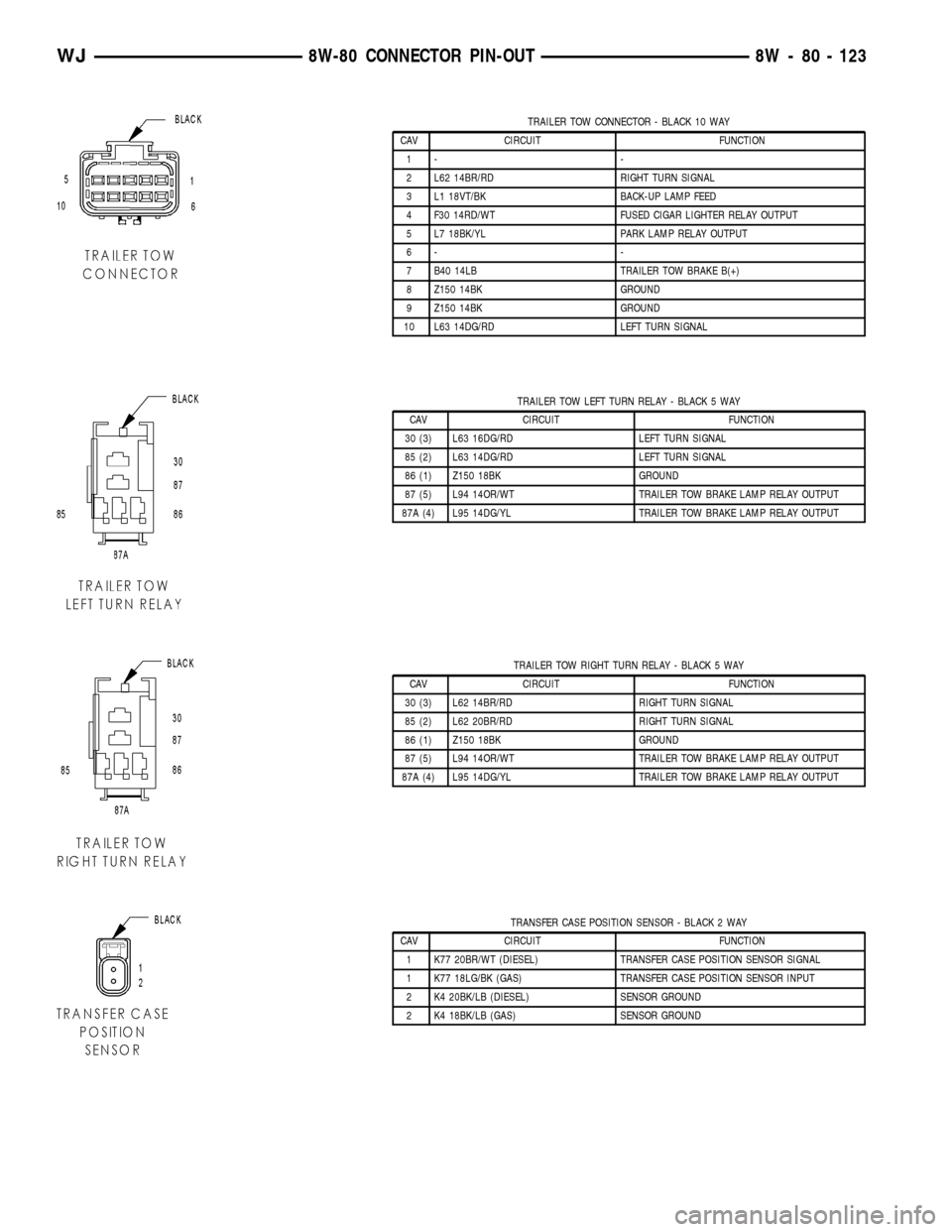
TRAILER TOW CONNECTOR - BLACK 10 WAY
CAV CIRCUIT FUNCTION
1- -
2 L62 14BR/RD RIGHT TURN SIGNAL
3 L1 18VT/BK BACK-UP LAMP FEED
4 F30 14RD/WT FUSED CIGAR LIGHTER RELAY OUTPUT
5 L7 18BK/YL PARK LAMP RELAY OUTPUT
6- -
7 B40 14LB TRAILER TOW BRAKE B(+)
8 Z150 14BK GROUND
9 Z150 14BK GROUND
10 L63 14DG/RD LEFT TURN SIGNAL
TRAILER TOW LEFT TURN RELAY - BLACK 5 WAY
CAV CIRCUIT FUNCTION
30 (3) L63 16DG/RD LEFT TURN SIGNAL
85 (2) L63 14DG/RD LEFT TURN SIGNAL
86 (1) Z150 18BK GROUND
87 (5) L94 14OR/WT TRAILER TOW BRAKE LAMP RELAY OUTPUT
87A (4) L95 14DG/YL TRAILER TOW BRAKE LAMP RELAY OUTPUT
TRAILER TOW RIGHT TURN RELAY - BLACK 5 WAY
CAV CIRCUIT FUNCTION
30 (3) L62 14BR/RD RIGHT TURN SIGNAL
85 (2) L62 20BR/RD RIGHT TURN SIGNAL
86 (1) Z150 18BK GROUND
87 (5) L94 14OR/WT TRAILER TOW BRAKE LAMP RELAY OUTPUT
87A (4) L95 14DG/YL TRAILER TOW BRAKE LAMP RELAY OUTPUT
TRANSFER CASE POSITION SENSOR - BLACK 2 WAY
CAV CIRCUIT FUNCTION
1 K77 20BR/WT (DIESEL) TRANSFER CASE POSITION SENSOR SIGNAL
1 K77 18LG/BK (GAS) TRANSFER CASE POSITION SENSOR INPUT
2 K4 20BK/LB (DIESEL) SENSOR GROUND
2 K4 18BK/LB (GAS) SENSOR GROUND
WJ8W-80 CONNECTOR PIN-OUT 8W - 80 - 123
Page 1176 of 2199
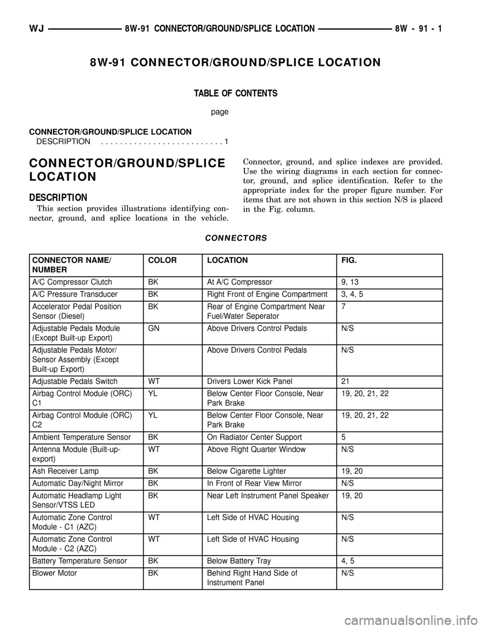
8W-91 CONNECTOR/GROUND/SPLICE LOCATION
TABLE OF CONTENTS
page
CONNECTOR/GROUND/SPLICE LOCATION
DESCRIPTION..........................1
CONNECTOR/GROUND/SPLICE
LOCATION
DESCRIPTION
This section provides illustrations identifying con-
nector, ground, and splice locations in the vehicle.Connector, ground, and splice indexes are provided.
Use the wiring diagrams in each section for connec-
tor, ground, and splice identification. Refer to the
appropriate index for the proper figure number. For
items that are not shown in this section N/S is placed
in the Fig. column.
CONNECTORS
CONNECTOR NAME/
NUMBERCOLOR LOCATION FIG.
A/C Compressor Clutch BK At A/C Compressor 9, 13
A/C Pressure Transducer BK Right Front of Engine Compartment 3, 4, 5
Accelerator Pedal Position
Sensor (Diesel)BK Rear of Engine Compartment Near
Fuel/Water Seperator7
Adjustable Pedals Module
(Except Built-up Export)GN Above Drivers Control Pedals N/S
Adjustable Pedals Motor/
Sensor Assembly (Except
Built-up Export)Above Drivers Control Pedals N/S
Adjustable Pedals Switch WT Drivers Lower Kick Panel 21
Airbag Control Module (ORC)
C1YL Below Center Floor Console, Near
Park Brake19, 20, 21, 22
Airbag Control Module (ORC)
C2YL Below Center Floor Console, Near
Park Brake19, 20, 21, 22
Ambient Temperature Sensor BK On Radiator Center Support 5
Antenna Module (Built-up-
export)WT Above Right Quarter Window N/S
Ash Receiver Lamp BK Below Cigarette Lighter 19, 20
Automatic Day/Night Mirror BK In Front of Rear View Mirror N/S
Automatic Headlamp Light
Sensor/VTSS LEDBK Near Left Instrument Panel Speaker 19, 20
Automatic Zone Control
Module - C1 (AZC)WT Left Side of HVAC Housing N/S
Automatic Zone Control
Module - C2 (AZC)WT Left Side of HVAC Housing N/S
Battery Temperature Sensor BK Below Battery Tray 4, 5
Blower Motor BK Behind Right Hand Side of
Instrument PanelN/S
WJ8W-91 CONNECTOR/GROUND/SPLICE LOCATION 8W - 91 - 1
Page 1178 of 2199
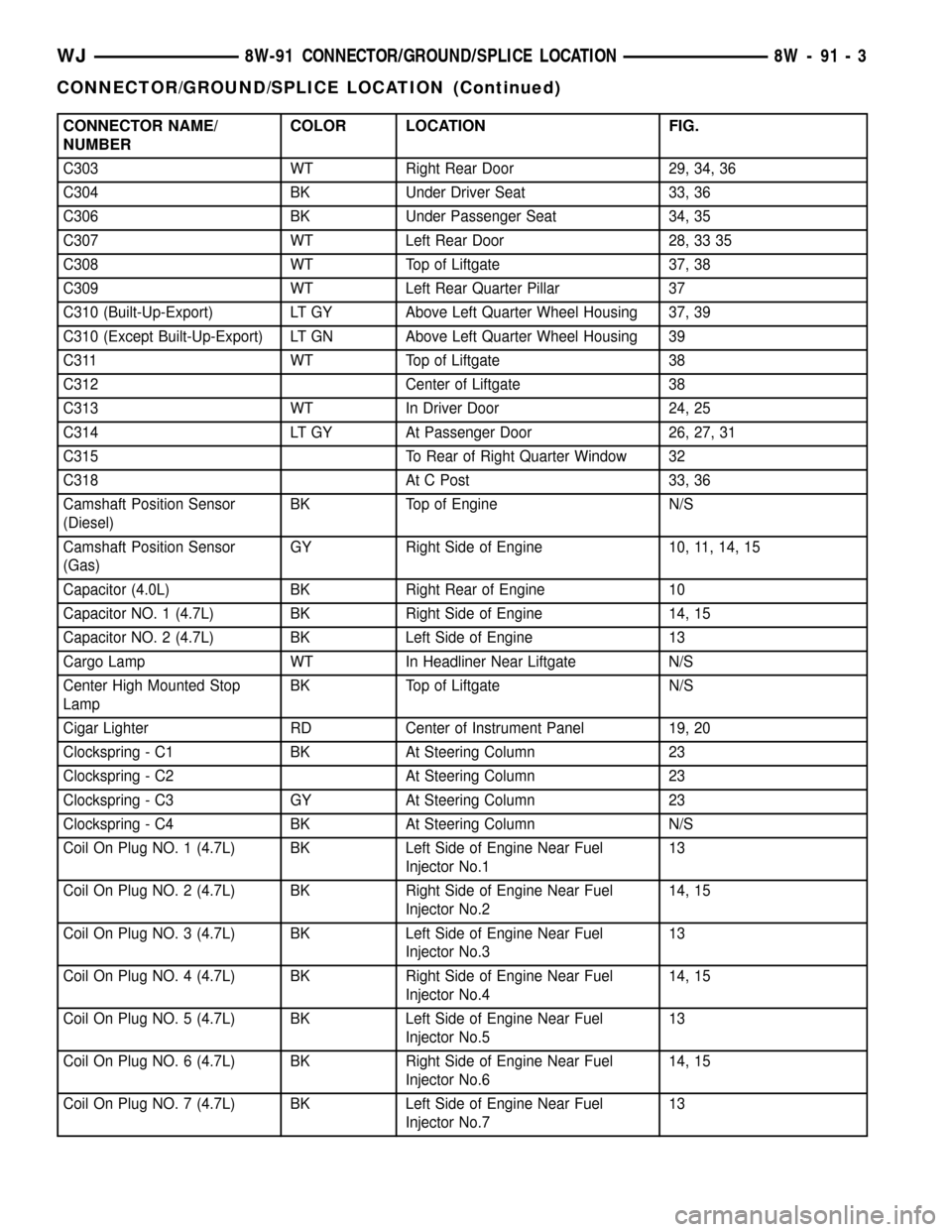
CONNECTOR NAME/
NUMBERCOLOR LOCATION FIG.
C303 WT Right Rear Door 29, 34, 36
C304 BK Under Driver Seat 33, 36
C306 BK Under Passenger Seat 34, 35
C307 WT Left Rear Door 28, 33 35
C308 WT Top of Liftgate 37, 38
C309 WT Left Rear Quarter Pillar 37
C310 (Built-Up-Export) LT GY Above Left Quarter Wheel Housing 37, 39
C310 (Except Built-Up-Export) LT GN Above Left Quarter Wheel Housing 39
C311 WT Top of Liftgate 38
C312 Center of Liftgate 38
C313 WT In Driver Door 24, 25
C314 LT GY At Passenger Door 26, 27, 31
C315 To Rear of Right Quarter Window 32
C318 At C Post 33, 36
Camshaft Position Sensor
(Diesel)BK Top of Engine N/S
Camshaft Position Sensor
(Gas)GY Right Side of Engine 10, 11, 14, 15
Capacitor (4.0L) BK Right Rear of Engine 10
Capacitor NO. 1 (4.7L) BK Right Side of Engine 14, 15
Capacitor NO. 2 (4.7L) BK Left Side of Engine 13
Cargo Lamp WT In Headliner Near Liftgate N/S
Center High Mounted Stop
LampBK Top of Liftgate N/S
Cigar Lighter RD Center of Instrument Panel 19, 20
Clockspring - C1 BK At Steering Column 23
Clockspring - C2 At Steering Column 23
Clockspring - C3 GY At Steering Column 23
Clockspring - C4 BK At Steering Column N/S
Coil On Plug NO. 1 (4.7L) BK Left Side of Engine Near Fuel
Injector No.113
Coil On Plug NO. 2 (4.7L) BK Right Side of Engine Near Fuel
Injector No.214, 15
Coil On Plug NO. 3 (4.7L) BK Left Side of Engine Near Fuel
Injector No.313
Coil On Plug NO. 4 (4.7L) BK Right Side of Engine Near Fuel
Injector No.414, 15
Coil On Plug NO. 5 (4.7L) BK Left Side of Engine Near Fuel
Injector No.513
Coil On Plug NO. 6 (4.7L) BK Right Side of Engine Near Fuel
Injector No.614, 15
Coil On Plug NO. 7 (4.7L) BK Left Side of Engine Near Fuel
Injector No.713
WJ8W-91 CONNECTOR/GROUND/SPLICE LOCATION 8W - 91 - 3
CONNECTOR/GROUND/SPLICE LOCATION (Continued)
Page 1189 of 2199
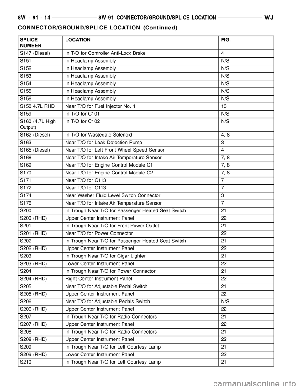
SPLICE
NUMBERLOCATION FIG.
S147 (Diesel) In T/O for Controller Anti-Lock Brake 4
S151 In Headlamp Assembly N/S
S152 In Headlamp Assembly N/S
S153 In Headlamp Assembly N/S
S154 In Headlamp Assembly N/S
S155 In Headlamp Assembly N/S
S156 In Headlamp Assembly N/S
S158 4.7L RHD Near T/O for Fuel Injector No. 1 13
S159 In T/O for C101 N/S
S160 (4.7L High
Output)In T/O for C102 N/S
S162 (Diesel) In T/O for Wastegate Solenoid 4, 8
S163 Near T/O for Leak Detection Pump 3
S165 (Diesel) Near T/O for Left Front Wheel Speed Sensor 4
S168 Near T/O for Intake Air Temperature Sensor 7, 8
S169 Near T/O for Engine Control Module C1 7, 8
S170 Near T/O for Engine Control Module C2 7, 8
S171 Near T/O for C113 7
S172 Near T/O for C113 7
S174 Near Washer Fluid Level Switch Connector 3
S176 Near T/O for Intake Air Temperature Sensor 7
S200 In Trough Near T/O for Passenger Heated Seat Switch 21
S200 (RHD) Upper Center Instrument Panel 22
S201 In Trough Near T/O for Front Power Outlet 21
S201 (RHD) Near T/O for Power Connector 22
S202 In Trough Near T/O for Passenger Heated Seat Switch 21
S202 (RHD) Upper Center Instrument Panel 22
S203 In Trough Near T/O for Cigar Lighter 21
S203 (RHD) Lower Center Instrument Panel 22
S204 In Trough Near T/O for Power Connector 21
S204 (RHD) Right Center Instrument Panel 22
S205 Near T/O for Adjustable Pedal Switch 21
S205 (RHD) Upper Center Instrument Panel 22
S206 Near T/O for Adjustable Pedals Switch N/S
S206 (RHD) Upper Center Instrument Panel 22
S207 In Trough Near T/O for Radio Connectors 21
S207 (RHD) Upper Center Instrument Panel 22
S208 In Trough Near T/O for Radio Connectors 21
S208 (RHD) Upper Center Instrument Panel 22
S209 In Trough Near T/O for Left Courtesy Lamp 21
S209 (RHD) Lower Center Instrument Panel 22
S210 In Trough Near T/O for Left Courtesy Lamp 21
8W - 91 - 14 8W-91 CONNECTOR/GROUND/SPLICE LOCATIONWJ
CONNECTOR/GROUND/SPLICE LOCATION (Continued)
Page 1226 of 2199

8W-97 POWER DISTRIBUTION
TABLE OF CONTENTS
page page
POWER DISTRIBUTION
DESCRIPTION..........................1
OPERATION............................1
SPECIAL TOOLS
POWER DISTRIBUTION SYSTEMS.........2
CIGAR LIGHTER OUTLET
DESCRIPTION..........................2
OPERATION............................2
DIAGNOSIS AND TESTING - CIGAR LIGHTER
OUTLET.............................2
CIGAR LIGHTER OUTLET DOOR SPRING
REMOVAL.............................3
INSTALLATION..........................3
IOD FUSE
DESCRIPTION..........................3
OPERATION............................4
REMOVAL.............................4
INSTALLATION..........................4
JUNCTION BLOCK
DESCRIPTION..........................5
OPERATION............................5
REMOVAL.............................5
INSTALLATION..........................6
POWER DISTRIBUTION CENTER
DESCRIPTION..........................7
OPERATION............................8
REMOVAL.............................8
DISASSEMBLY
POWER DISTRIBUTION CENTER
DISASSEMBLY........................9ASSEMBLY
POWER DISTRIBUTION CENTER
ASSEMBLY..........................11
INSTALLATION.........................12
POWER OUTLET
DESCRIPTION - FRONT POWER OUTLET....12
OPERATION - FRONT POWER OUTLET......12
DIAGNOSIS AND TESTING - POWER OUTLET . 12
REMOVAL.............................13
INSTALLATION.........................13
POWER OUTLET RELAY
DESCRIPTION.........................13
OPERATION...........................14
DIAGNOSIS AND TESTING - POWER OUTLET
RELAY..............................14
REMOVAL.............................15
INSTALLATION.........................15
IOD WIRE HARNESS CONNECTOR
DESCRIPTION.........................15
OPERATION...........................15
FUSE COVER
REMOVAL.............................16
INSTALLATION.........................16
REAR POWER OUTLET
DESCRIPTION - REAR POWER OUTLET.....16
OPERATION - REAR POWER OUTLET.......17
DIAGNOSIS AND TESTING - REAR POWER
OUTLET............................17
REMOVAL.............................17
INSTALLATION.........................18
POWER DISTRIBUTION
DESCRIPTION
This group covers the various standard and
optional power distribution components used on this
model. The power distribution system for this vehicle
consists of the following components:
²Power Distribution Center (PDC)
²Junction Block (JB)
²Power Outlets
The power distribution system also incorporates
various types of circuit control and protection fea-
tures, including:
²Automatic resetting circuit breakers
²Blade-type fuses
²Bus bars
²Cartridge fuses²Circuit splice blocks
²Flashers
²Fusible links
²Standard and Micro-Relays
Following are general descriptions of the major
components in the power distribution system. See the
owner's manual in the vehicle glove box for more
information on the features and use of all of the
power distribution system components. Refer to Wir-
ing Diagrams for complete circuit diagrams.
OPERATION
The power distribution system for this vehicle is
designed to provide safe, reliable, and centralized dis-
tribution points for the electrical current required to
operate all of the standard and optional factory-in-
stalled electrical and electronic powertrain, chassis,
safety, security, comfort and convenience systems. At
WJ8W-97 POWER DISTRIBUTION 8W - 97 - 1
Page 1227 of 2199

the same time, the power distribution system was
designed to provide ready access to these electrical
distribution points for the vehicle technician to use
when conducting diagnosis and repair of faulty cir-
cuits. The power distribution system can also prove
useful for the sourcing of additional electrical circuits
that may be required to provide the electrical current
needed to operate accessories that the vehicle owner
may choose to have installed in the aftermarket.
NOTE: DO NOT ATTEMPT TO SWAP POWER DIS-
TRIBUTION CENTERS FROM ONE VEHICLE TO
ANOTHER. MOST OF THESE ASSEMBLIES ARE
VEHICLE FEATURE SPECIFIC AND THEREFORE
NOT INTERCHANGEABLE. ALWAYS USE THE COR-
RECT PART NUMBERED ASSEMBLY WHEN DIAG-
NOSING OR REPLACING A POWER DISTRIBUTION
CENTER.
SPECIAL TOOLS
POWER DISTRIBUTION SYSTEMS
CIGAR LIGHTER OUTLET
DESCRIPTION
A cigar lighter outlet is standard equipment on
this model. On models equipped with the optional
Smoker's Package, the cigar lighter knob and heating
element are included. On models without the Smok-
er's Package, the cigar lighter outlet is equipped with
a snap fit plastic cap and is treated as an extra
accessory power outlet. The cigar lighter outlet is
installed in the instrument panel center lower bezel,
which is located near the bottom of the instrument
panel center stack area, below the heater and air
conditioner controls. The cigar lighter outlet is
secured by a snap fit within the center lower bezel.The cigar lighter outlet, plastic cap and the knob
and heating element unit are available for service
replacement. These components cannot be repaired
and, if faulty or damaged, they must be replaced.
OPERATION
The cigar lighter consists of two major components:
a knob and heating element unit, and the cigar
lighter base or outlet shell. The receptacle shell is
connected to ground, and an insulated contact in the
bottom of the shell is connected to battery current.
The cigar lighter receives battery voltage from a fuse
in the junction block when the ignition switch is in
the Accessory or On positions.
The cigar lighter knob and heating element are
encased within a spring-loaded housing, which also
features a sliding protective heat shield. When the
knob and heating element are inserted in the outlet
shell, the heating element resistor coil is grounded
through its housing to the outlet shell. If the cigar
lighter knob is pushed inward, the heat shield slides
up toward the knob exposing the heating element,
and the heating element extends from the housing
toward the insulated contact in the bottom of the
outlet shell.
Two small spring-clip retainers are located on
either side of the insulated contact inside the bottom
of the outlet shell. These clips engage and hold the
heating element against the insulated contact long
enough for the resistor coil to heat up. When the
heating element is engaged with the contact, battery
current can flow through the resistor coil to ground,
causing the resistor coil to heat.
When the resistor coil becomes sufficiently heated,
excess heat radiates from the heating element caus-
ing the spring-clips to expand. Once the spring-clips
expand far enough to release the heating element,
the spring-loaded housing forces the knob and heat-
ing element to pop back outward to their relaxed
position. When the cigar lighter knob and element
are pulled out of the outlet shell, the protective heat
shield slides downward on the housing so that the
heating element is recessed and shielded around its
circumference for safety.
DIAGNOSIS AND TESTING - CIGAR LIGHTER
OUTLET
For complete circuit diagrams, refer toHorn/Ci-
gar Lighter/Power Outletin Wiring Diagrams.
(1) Check the fused B(+) fuse in the junction block.
If OK, go to Step 2. If not OK, repair the shorted cir-
cuit or component as required and replace the faulty
fuse.
(2) Turn the ignition switch to the On position.
Check for battery voltage at the fused B(+) fuse in
Terminal Pick Kit 6680
8W - 97 - 2 8W-97 POWER DISTRIBUTIONWJ
POWER DISTRIBUTION (Continued)