Cylinder order JEEP GRAND CHEROKEE 2003 WJ / 2.G User Guide
[x] Cancel search | Manufacturer: JEEP, Model Year: 2003, Model line: GRAND CHEROKEE, Model: JEEP GRAND CHEROKEE 2003 WJ / 2.GPages: 2199, PDF Size: 76.01 MB
Page 595 of 2199

tion feature of the ITM can be disabled by depressing
the ªLockº button on the RKE transmitter three
times or cycling the key in the driver door cylinder
from the center to lock position within fifteen seconds
during VTA arming, while the security indicator is
still flashing rapidly. The VTA provides a single short
siren ªchirpº as an audible conformation that the
motion detect disable request has been received. The
ITM must be electronically enabled in order for the
intrusion alarm to perform as designed. The intru-
sion alarm function of the ITM is enabled on vehicles
equipped with this option at the factory, but a service
replacement ITM must be configured and enabled by
the dealer using the DRBIIItscan tool. Refer to the
appropriate diagnostic information.
OPERATION - SENTRY KEY IMMOBILIZER
SYSTEM
The Sentry Key Immobilizer System (SKIS) is
designed to provide passive protection against unau-
thorized vehicle use by disabling the engine after
about two seconds of running, whenever any method
other than a valid Sentry Key is used to start the
vehicle. The SKIS is considered a passive protection
system because it is always active when the ignition
system is energized and does not require any cus-
tomer intervention. The SKIS uses Radio Frequency
(RF) communication to obtain confirmation that the
key in the ignition switch is a valid key for operating
the vehicle. The microprocessor-based SKIS hard-
ware and software also uses messages to communi-
cate with other modules in the vehicle over the
Programmable Communications Interface (PCI) data
bus. (Refer to 8 - ELECTRICAL/ELECTRONIC CON-
TROL MODULES/COMMUNICATION - OPERA-
TION).
Pre-programmed Sentry Key transponders are pro-
vided with the vehicle from the factory. Each Sentry
Key Immobilizer Module (SKIM) will recognize a
maximum of eight Sentry Keys. If the customer
would like additional keys other than those provided
with the vehicle, they may be purchased from any
authorized dealer. These additional keys must be pro-
grammed to the SKIM in the vehicle in order for the
system to recognize them as valid keys. This can be
done by the dealer using a DRBIIItscan tool or, if
Customer Learn programming is an available SKIS
feature in the market where the vehicle was pur-
chased, the customer can program the additional
keys, as long as at least two valid Sentry Keys are
already available. (Refer to 8 - ELECTRICAL/VEHI-
CLE THEFT SECURITY - STANDARD PROCE-
DURE - TRANSPONDER PROGRAMMING).
The SKIS performs a self-test each time the igni-
tion switch is turned to the On position, and will
store fault information in the form of DiagnosticTrouble Codes (DTC's) if a system malfunction is
detected. Refer to the appropriate diagnostic informa-
tion.
DIAGNOSIS AND TESTING
DIAGNOSIS AND TESTING - VEHICLE THEFT
SECURITY SYSTEM
The VTSS-related hard wired inputs to and out-
puts from the Body Control Module (BCM), the
Driver Door Module (DDM), or the Passenger Door
Module (PDM) may be diagnosed and tested using
conventional diagnostic tools and procedures. Refer
to the appropriate wiring information.
However, conventional diagnostic methods may not
prove conclusive in the diagnosis of the BCM, the
DDM, the PDM, or the Programmable Communica-
tions Interface (PCI) data bus network. In order to
obtain conclusive testing of the VTSS, the BCM, the
DDM, the PDM, and the PCI data bus network must
also be checked. The most reliable, efficient, and
accurate means to diagnose the VTSS requires the
use of a DRBIIItscan tool and the appropriate diag-
nostic information.
WARNING: ON VEHICLES EQUIPPED WITH AIR-
BAGS, DISABLE THE AIRBAG SYSTEM BEFORE
ATTEMPTING ANY STEERING WHEEL, STEERING
COLUMN, OR INSTRUMENT PANEL COMPONENT
DIAGNOSIS OR SERVICE. DISCONNECT AND ISO-
LATE THE BATTERY NEGATIVE (GROUND) CABLE,
THEN WAIT TWO MINUTES FOR THE AIRBAG SYS-
TEM CAPACITOR TO DISCHARGE BEFORE PER-
FORMING FURTHER DIAGNOSIS OR SERVICE. THIS
IS THE ONLY SURE WAY TO DISABLE THE AIRBAG
SYSTEM. FAILURE TO TAKE THE PROPER PRE-
CAUTIONS COULD RESULT IN ACCIDENTAL AIR-
BAG DEPLOYMENT AND POSSIBLE PERSONAL
INJURY.
8Q - 4 VEHICLE THEFT SECURITYWJ
VEHICLE THEFT SECURITY (Continued)
Page 1245 of 2199

REMOVAL
REMOVAL - CAMSHAFT BEARINGS.......31
REMOVAL - CAMSHAFT................31
INSPECTION
INSPECTION - CAMSHAFT BEARINGS.....31
INSPECTION - CAMSHAFT..............31
INSTALLATION
INSTALLATION - CAMSHAFT BEARINGS . . . 32
INSTALLATION - CAMSHAFT............32
CONNECTING ROD BEARINGS
STANDARD PROCEDURE - FITTING
CONNECTING ROD BEARINGS..........33
CRANKSHAFT
DESCRIPTION.........................35
CRANKSHAFT MAIN BEARINGS
STANDARD PROCEDURE - FITTING
CRANKSHAFT MAIN BEARINGS..........36
REMOVAL.............................39
INSPECTION..........................40
INSTALLATION.........................40
CRANKSHAFT OIL SEAL - FRONT
REMOVAL.............................41
INSTALLATION.........................41
CRANKSHAFT OIL SEAL - REAR
REMOVAL.............................42
INSTALLATION.........................42
HYDRAULIC LIFTERS
DESCRIPTION.........................43
REMOVAL.............................43
CLEANING............................43
INSPECTION..........................43
INSTALLATION.........................43
PISTON & CONNECTING ROD
DESCRIPTION.........................44
STANDARD PROCEDURE - PISTON FITTING . 44
REMOVAL.............................45
INSTALLATION.........................46
PISTON RINGS
STANDARD PROCEDURE - PISTON RING
FITTING.............................47
VIBRATION DAMPER
REMOVAL.............................49
INSTALLATION.........................49STRUCTURAL SUPPORT
REMOVAL.............................49
INSTALLATION.........................50
LUBRICATION
DESCRIPTION.........................50
OPERATION...........................50
DIAGNOSIS AND TESTING
DIAGNOSIS AND TESTING - ENGINE OIL
PRESSURE..........................51
DIAGNOSIS AND TESTING - ENGINE OIL
LEAK...............................51
OIL
STANDARD PROCEDURE - ENGINE OIL
SERVICE............................53
OIL FILTER
REMOVAL.............................53
INSTALLATION.........................54
OIL PAN
DESCRIPTION.........................54
REMOVAL.............................54
INSTALLATION.........................55
ENGINE OIL PRESSURE SENSOR
DESCRIPTION.........................56
OPERATION...........................56
OIL PUMP
REMOVAL.............................56
INSTALLATION.........................57
INTAKE MANIFOLD
DESCRIPTION.........................57
DIAGNOSIS AND TESTING - INTAKE
MANIFOLD LEAKAGE..................57
REMOVAL.............................57
INSTALLATION.........................57
EXHAUST MANIFOLD
DESCRIPTION.........................58
REMOVAL.............................58
INSTALLATION.........................58
TIMING BELT / CHAIN COVER(S)
REMOVAL.............................58
INSTALLATION.........................58
TIMING BELT/CHAIN AND SPROCKETS
REMOVAL.............................60
INSTALLATION.........................60
ENGINE - 4.0L
DESCRIPTION
The 4.0 Liter (242 CID) six-cylinder engine is an
In-line, lightweight, overhead valve engine. This
engine is designed for unleaded fuel.
The engine cylinder head has dual quench-type
combustion chambers that create turbulence and fast
burning of the air/fuel mixture. This results in better
fuel economy.
The cylinders are numbered 1 through 6 from front
to rear. The firing order is 1-5-3-6-2-4 (Fig. 1).The crankshaft rotation is clockwise, when viewed
from the front of the engine. The crankshaft rotates
within seven main bearings. The camshaft rotates
within four bearings.
The engine Build Date Code is located on a
machined surface on the right side of the cylinder
block between the No.2 and No.3 cylinders (Fig. 2).
The digits of the code identify:
²1st DigitÐThe year (8 = 1998).
²2nd & 3rd DigitsÐThe month (01 - 12).
²4th & 5th DigitsÐThe engine type/fuel system/
compression ratio (MX = A 4.0 Liter (242 CID) 8.7:1
compression ratio engine with a multi-point fuel
injection system).
9 - 2 ENGINE - 4.0LWJ
Page 1246 of 2199
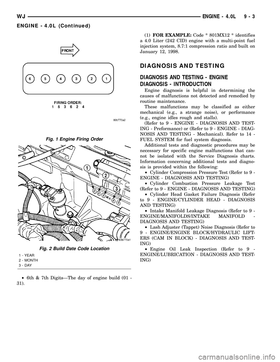
²6th & 7th DigitsÐThe day of engine build (01 -
31).(1)FOR EXAMPLE:Code * 801MX12 * identifies
a 4.0 Liter (242 CID) engine with a multi-point fuel
injection system, 8.7:1 compression ratio and built on
January 12, 1998.
DIAGNOSIS AND TESTING
DIAGNOSIS AND TESTING - ENGINE
DIAGNOSIS - INTRODUCTION
Engine diagnosis is helpful in determining the
causes of malfunctions not detected and remedied by
routine maintenance.
These malfunctions may be classified as either
mechanical (e.g., a strange noise), or performance
(e.g., engine idles rough and stalls).
(Refer to 9 - ENGINE - DIAGNOSIS AND TEST-
ING - Preformance) or (Refer to 9 - ENGINE - DIAG-
NOSIS AND TESTING - Mechanical). Refer to 14 -
FUEL SYSTEM for fuel system diagnosis.
Additional tests and diagnostic procedures may be
necessary for specific engine malfunctions that can-
not be isolated with the Service Diagnosis charts.
Information concerning additional tests and diagno-
sis is provided within the following:
²Cylinder Compression Pressure Test (Refer to 9 -
ENGINE - DIAGNOSIS AND TESTING)
²Cylinder Combustion Pressure Leakage Test
(Refer to 9 - ENGINE - DIAGNOSIS AND TESTING)
²Cylinder Head Gasket Failure Diagnosis (Refer
to 9 - ENGINE/CYLINDER HEAD - DIAGNOSIS
AND TESTING)
²Intake Manifold Leakage Diagnosis (Refer to 9 -
ENGINE/MANIFOLDS/INTAKE MANIFOLD -
DIAGNOSIS AND TESTING)
²Lash Adjuster (Tappet) Noise Diagnosis (Refer to
9 - ENGINE/ENGINE BLOCK/HYDRAULIC LIFT-
ERS (CAM IN BLOCK) - DIAGNOSIS AND TEST-
ING)
²Engine Oil Leak Inspection (Refer to 9 -
ENGINE/LUBRICATION - DIAGNOSIS AND TEST-
ING)
Fig. 1 Engine Firing Order
Fig. 2 Build Date Code Location
1 - YEAR
2 - MONTH
3-DAY
WJENGINE - 4.0L 9 - 3
ENGINE - 4.0L (Continued)
Page 1257 of 2199
WARNING: USE EXTREME CAUTION WHEN THE
ENGINE IS OPERATING. DO NOT STAND IN A
DIRECT LINE WITH THE FAN. DO NOT PUT YOUR
HANDS NEAR THE PULLEYS, BELTS OR FAN. DO
NOT WEAR LOOSE CLOTHING.
(48) Start the engine, inspect for leaks and correct
the fluid levels, as necessary.
SPECIFICATIONS
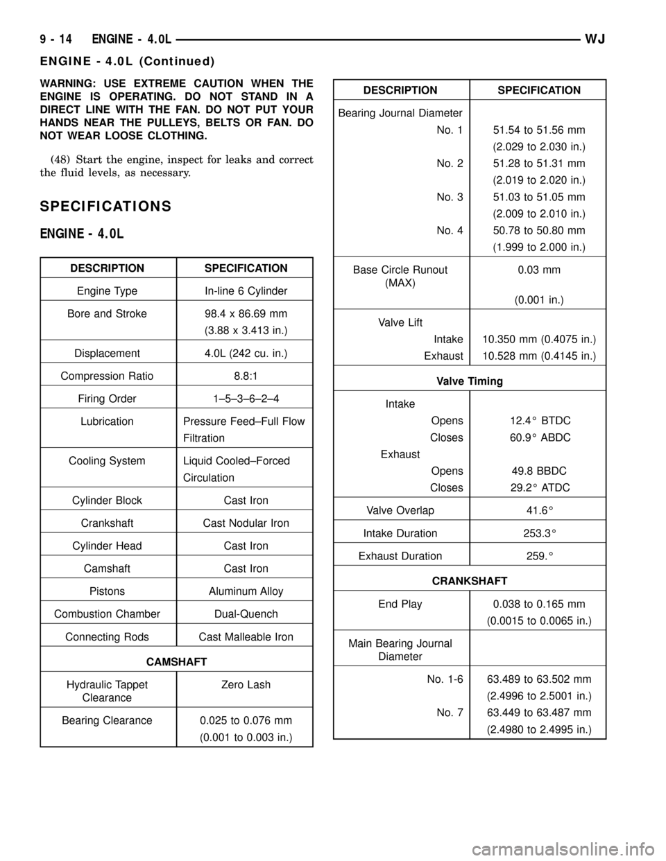
ENGINE - 4.0L
DESCRIPTION SPECIFICATION
Engine Type In-line 6 Cylinder
Bore and Stroke 98.4 x 86.69 mm
(3.88 x 3.413 in.)
Displacement 4.0L (242 cu. in.)
Compression Ratio 8.8:1
Firing Order 1±5±3±6±2±4
Lubrication Pressure Feed±Full Flow
Filtration
Cooling System Liquid Cooled±Forced
Circulation
Cylinder Block Cast Iron
Crankshaft Cast Nodular Iron
Cylinder Head Cast Iron
Camshaft Cast Iron
Pistons Aluminum Alloy
Combustion Chamber Dual-Quench
Connecting Rods Cast Malleable Iron
CAMSHAFT
Hydraulic Tappet
ClearanceZero Lash
Bearing Clearance 0.025 to 0.076 mm
(0.001 to 0.003 in.)
DESCRIPTION SPECIFICATION
Bearing Journal Diameter
No. 1 51.54 to 51.56 mm
(2.029 to 2.030 in.)
No. 2 51.28 to 51.31 mm
(2.019 to 2.020 in.)
No. 3 51.03 to 51.05 mm
(2.009 to 2.010 in.)
No. 4 50.78 to 50.80 mm
(1.999 to 2.000 in.)
Base Circle Runout
(MAX)0.03 mm
(0.001 in.)
Valve Lift
Intake 10.350 mm (0.4075 in.)
Exhaust 10.528 mm (0.4145 in.)
Valve Timing
Intake
Opens 12.4É BTDC
Closes 60.9É ABDC
Exhaust
Opens 49.8 BBDC
Closes 29.2É ATDC
Valve Overlap 41.6É
Intake Duration 253.3É
Exhaust Duration 259.É
CRANKSHAFT
End Play 0.038 to 0.165 mm
(0.0015 to 0.0065 in.)
Main Bearing Journal
Diameter
No. 1-6 63.489 to 63.502 mm
(2.4996 to 2.5001 in.)
No. 7 63.449 to 63.487 mm
(2.4980 to 2.4995 in.)
9 - 14 ENGINE - 4.0LWJ
ENGINE - 4.0L (Continued)
Page 1263 of 2199
(2) Drain the coolant (Refer to 7 - COOLING -
STANDARD PROCEDURE) and disconnect the hoses
at the engine thermostat housing and the water
pump inlet. DO NOT waste reusable coolant. If the
solution is clean and is being drained only to service
the engine or cooling system, drain the coolant into a
clean container for reuse.
(3) Remove the air cleaner assembly (Refer to 9 -
ENGINE/AIR INTAKE SYSTEM/AIR CLEANER
HOUSING - REMOVAL).
(4) Remove the cylinder head cover (Refer to 9 -
ENGINE/CYLINDER HEAD/CYLINDER HEAD
COVER(S) - REMOVAL).
(5) Remove the capscrews, bridge and pivot assem-
blies and rocker arms (Refer to 9 - ENGINE/CYLIN-
DER HEAD/ROCKER ARM / ADJUSTER ASSY -
REMOVAL).
(6) Remove the push rods.Retain the push rods,
bridges, pivots and rocker arms in the same
order as removed.
(7) Remove the accessory drive belt (Refer to 7 -
COOLING/ACCESSORY DRIVE/DRIVE BELTS -
REMOVAL).
(8) Remove the A/C compressor mounting bolts
and secure the compressor to the side.
(9) Remove the power steering pump and bracket
from the intake manifold and water pump. Set the
pump and bracket aside. DO NOT disconnect the
hoses.
(10) Perform the Fuel System Pressure Release
procedure. (Refer to 14 - FUEL SYSTEM/FUEL
DELIVERY - STANDARD PROCEDURE).
(11) Disconnect the fuel supply line at the fuel rail.(12) Remove the intake and exhaust manifolds
from the engine cylinder head (Refer to 9 - ENGINE/
MANIFOLDS/INTAKE MANIFOLD - REMOVAL).
(13) Remove the coil rail (Refer to 8 - ELECTRI-
CAL/IGNITION CONTROL/COIL RAIL - REMOV-
AL).
(14) Remove spark plugs (Refer to 8 - ELECTRI-
CAL/IGNITION CONTROL/SPARK PLUG - REMOV-
AL).
(15) Disconnect the temperature sending unit wire
connector.
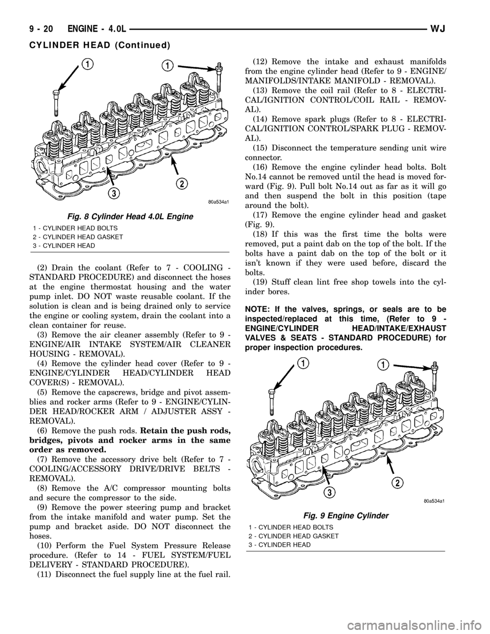
(16) Remove the engine cylinder head bolts. Bolt
No.14 cannot be removed until the head is moved for-
ward (Fig. 9). Pull bolt No.14 out as far as it will go
and then suspend the bolt in this position (tape
around the bolt).
(17) Remove the engine cylinder head and gasket
(Fig. 9).
(18) If this was the first time the bolts were
removed, put a paint dab on the top of the bolt. If the
bolts have a paint dab on the top of the bolt or it
isn't known if they were used before, discard the
bolts.
(19) Stuff clean lint free shop towels into the cyl-
inder bores.
NOTE: If the valves, springs, or seals are to be
inspected/replaced at this time, (Refer to 9 -
ENGINE/CYLINDER HEAD/INTAKE/EXHAUST
VALVES & SEATS - STANDARD PROCEDURE) for
proper inspection procedures.
Fig. 8 Cylinder Head 4.0L Engine
1 - CYLINDER HEAD BOLTS
2 - CYLINDER HEAD GASKET
3 - CYLINDER HEAD
Fig. 9 Engine Cylinder
1 - CYLINDER HEAD BOLTS
2 - CYLINDER HEAD GASKET
3 - CYLINDER HEAD
9 - 20 ENGINE - 4.0LWJ
CYLINDER HEAD (Continued)
Page 1265 of 2199

(12) Install the push rods, rocker arms, pivots and
bridges in the order they were removed (Refer to 9 -
ENGINE/CYLINDER HEAD/ROCKER ARM /
ADJUSTER ASSY - INSTALLATION).
(13) Install the engine cylinder head cover (Refer
to 9 - ENGINE/CYLINDER HEAD/CYLINDER
HEAD COVER(S) - INSTALLATION).
(14) Attach the air conditioner compressor mount-
ing bracket to the engine cylinder head and block.
Tighten the bolts to 40 N´m (30 ft. lbs.) torque.
(15) Attach the air conditioning compressor to the
bracket. Tighten the bolts to 27 N´m (20 ft. lbs.)
torque.
CAUTION: The serpentine drive belt must be routed
correctly. Incorrect routing can cause the water
pump to turn in the opposite direction causing the
engine to overheat.
(16) Install the serpentine drive belt. (Refer to 7 -
COOLING/ACCESSORY DRIVE/DRIVE BELTS -
INSTALLATION).
(17) Install the air cleaner and ducting.
(18) Connect the hoses to the engine thermostat
housing and fill the cooling system to the specified
level (Refer to 7 - COOLING - STANDARD PROCE-
DURE).
(19) The automatic transmission throttle linkage
and cable must be adjusted after completing the
engine cylinder head installation (Refer to 21 -
TRANSMISSION/TRANSAXLE/AUTOMATIC - AW4/
THROTTLE VALVE CABLE - ADJUSTMENTS).
(20) Install the temperature sending unit and con-
nect the wire connector.
(21) If equipped with air conditioning, install A/C
compressor (Refer to 24 - HEATING & AIR CONDI-
TIONING/PLUMBING/A/C COMPRESSOR -
INSTALLATION) and charge A/C system (Refer to 24
- HEATING & AIR CONDITIONING/PLUMBING -
STANDARD PROCEDURE).
(22) Connect negative cable to battery.
WARNING: USE EXTREME CAUTION WHEN THE
ENGINE IS OPERATING. DO NOT STAND IN DIRECT
LINE WITH THE FAN. DO NOT PUT HANDS NEAR
THE PULLEYS, BELTS OR FAN. DO NOT WEAR
LOOSE CLOTHING.
(23) Operate the engine with the radiator cap off.
Inspect for leaks and continue operating the engine
until the engine thermostat opens. Add coolant, if
required.CYLINDER HEAD COVER(S)
DESCRIPTION
The cylinder head cover (Fig. 11) is made of
stamped steel and incorporates the Crankcase Venti-
lation (CCV) Hoses and the oil fill opening.
REMOVAL
The cylinder head cover is isolated from the cylin-
der head via grommets and a reusable molded rubber
gasket. The grommet and limiter are retained in the
cylinder head cover.
(1) Disconnect negative cable from battery.
(2) Disconnect the Crankcase Ventilation (CCV)
vacuum hose from engine cylinder head cover.
(3) Disconnect the fresh air inlet hose from the
engine cylinder head cover.
(4) Disconnect the accelerator, transmission, and
speed (if equipped) control cables from the throttle
body (Fig. 12).
(5) Remove the three bolts that fasten the control
cable bracket to the intake manifold.
(6) Remove control cables from cylinder head cover
clip.
(7) Position control cables and bracket away from
cylinder head cover secure with tie straps.
(8) Remove the engine cylinder head cover mount-
ing bolts.
(9) Remove the engine cylinder head cover and
gasket.
Fig. 11 Cylinder Head Cover
9 - 22 ENGINE - 4.0LWJ
CYLINDER HEAD (Continued)
Page 1268 of 2199
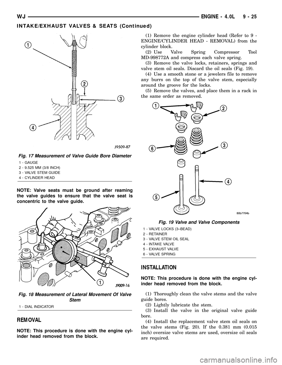
NOTE: Valve seats must be ground after reaming
the valve guides to ensure that the valve seat is
concentric to the valve guide.
REMOVAL
NOTE: This procedure is done with the engine cyl-
inder head removed from the block.(1) Remove the engine cylinder head (Refer to 9 -
ENGINE/CYLINDER HEAD - REMOVAL) from the
cylinder block.
(2) Use Valve Spring Compressor Tool
MD-998772A and compress each valve spring.
(3) Remove the valve locks, retainers, springs and
valve stem oil seals. Discard the oil seals (Fig. 19).
(4) Use a smooth stone or a jewelers file to remove
any burrs on the top of the valve stem, especially
around the groove for the locks.
(5) Remove the valves, and place them in a rack in
the same order as removed.
INSTALLATION
NOTE: This procedure is done with the engine cyl-
inder head removed from the block.
(1) Thoroughly clean the valve stems and the valve
guide bores.
(2) Lightly lubricate the stem.
(3) Install the valve in the original valve guide
bore.
(4) Install the replacement valve stem oil seals on
the valve stems (Fig. 20). If the 0.381 mm (0.015
inch) oversize valve stems are used, oversize oil seals
are required.
Fig. 17 Measurement of Valve Guide Bore Diameter
1 - GAUGE
2 - 9.525 MM (3/8 INCH)
3 - VALVE STEM GUIDE
4 - CYLINDER HEAD
Fig. 18 Measurement of Lateral Movement Of Valve
Stem
1 - DIAL INDICATOR
Fig. 19 Valve and Valve Components
1 - VALVE LOCKS (3±BEAD)
2 - RETAINER
3 - VALVE STEM OIL SEAL
4 - INTAKE VALVE
5 - EXHAUST VALVE
6 - VALVE SPRING
WJENGINE - 4.0L 9 - 25
INTAKE/EXHAUST VALVES & SEATS (Continued)
Page 1269 of 2199
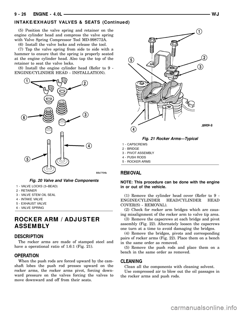
(5) Position the valve spring and retainer on the
engine cylinder head and compress the valve spring
with Valve Spring Compressor Tool MD-998772A.
(6) Install the valve locks and release the tool.
(7) Tap the valve spring from side to side with a
hammer to ensure that the spring is properly seated
at the engine cylinder head. Also tap the top of the
retainer to seat the valve locks.
(8) Install the engine cylinder head (Refer to 9 -
ENGINE/CYLINDER HEAD - INSTALLATION).
ROCKER ARM / ADJUSTER
ASSEMBLY
DESCRIPTION
The rocker arms are made of stamped steel and
have a operational ratio of 1.6:1 (Fig. 21).
OPERATION
When the push rods are forced upward by the cam-
shaft lobes the push rod presses upward on the
rocker arms, the rocker arms pivot, forcing down-
ward pressure on the valves forcing the valves to
move downward and off from their seats.
REMOVAL
NOTE: This procedure can be done with the engine
in or out of the vehicle.
(1) Remove the cylinder head cover (Refer to 9 -
ENGINE/CYLINDER HEAD/CYLINDER HEAD
COVER(S) - REMOVAL).
(2) Check for rocker arm bridges which are caus-
ing misalignment of the rocker arm to valve tip area.
(3) Remove the capscrews at each bridge and pivot
assembly (Fig. 22). Alternately loosen the capscrews
one turn at a time to avoid damaging the bridges.
(4) Remove the bridges, pivots and corresponding
pairs of rocker arms (Fig. 22). Place them on a bench
in the same order as removed.
(5) Remove the push rods and place them on a
bench in the same order as removed.
CLEANING
Clean all the components with cleaning solvent.
Use compressed air to blow out the oil passages in
the rocker arms and push rods.
Fig. 20 Valve and Valve Components
1 - VALVE LOCKS (3±BEAD)
2 - RETAINER
3 - VALVE STEM OIL SEAL
4 - INTAKE VALVE
5 - EXHAUST VALVE
6 - VALVE SPRING
Fig. 21 Rocker ArmsÐTypical
1 - CAPSCREWS
2 - BRIDGE
3 - PIVOT ASSEMBLY
4 - PUSH RODS
5 - ROCKER ARMS
9 - 26 ENGINE - 4.0LWJ
INTAKE/EXHAUST VALVES & SEATS (Continued)
Page 1272 of 2199
(2) Remove cap screws, bridge and pivot assem-
blies and rocker arms (Refer to 9 - ENGINE/CYLIN-
DER HEAD/ROCKER ARM / ADJUSTER ASSY -
REMOVAL) for access to each valve spring to be
removed.
(3) Remove push rods.Retain the push rods,
bridges, pivots and rocker arms in the same
order and position as removed.
(4) Inspect the springs and retainer for cracks and
possible signs of weakening.
(5) Remove the spark plug(s) adjacent to the cylin-
der(s) below the valve springs to be removed.
(6) Connect an air hose to the adapter and apply
air pressure slowly. Maintain at least 621 kPa (90
psi) of air pressure in the cylinder to hold the valves
against their seats. For vehicles equipped with an air
conditioner, use a flexible air adaptor when servicing
the No.1 cylinder.
(7) Tap the retainer or tip with a rawhide hammer
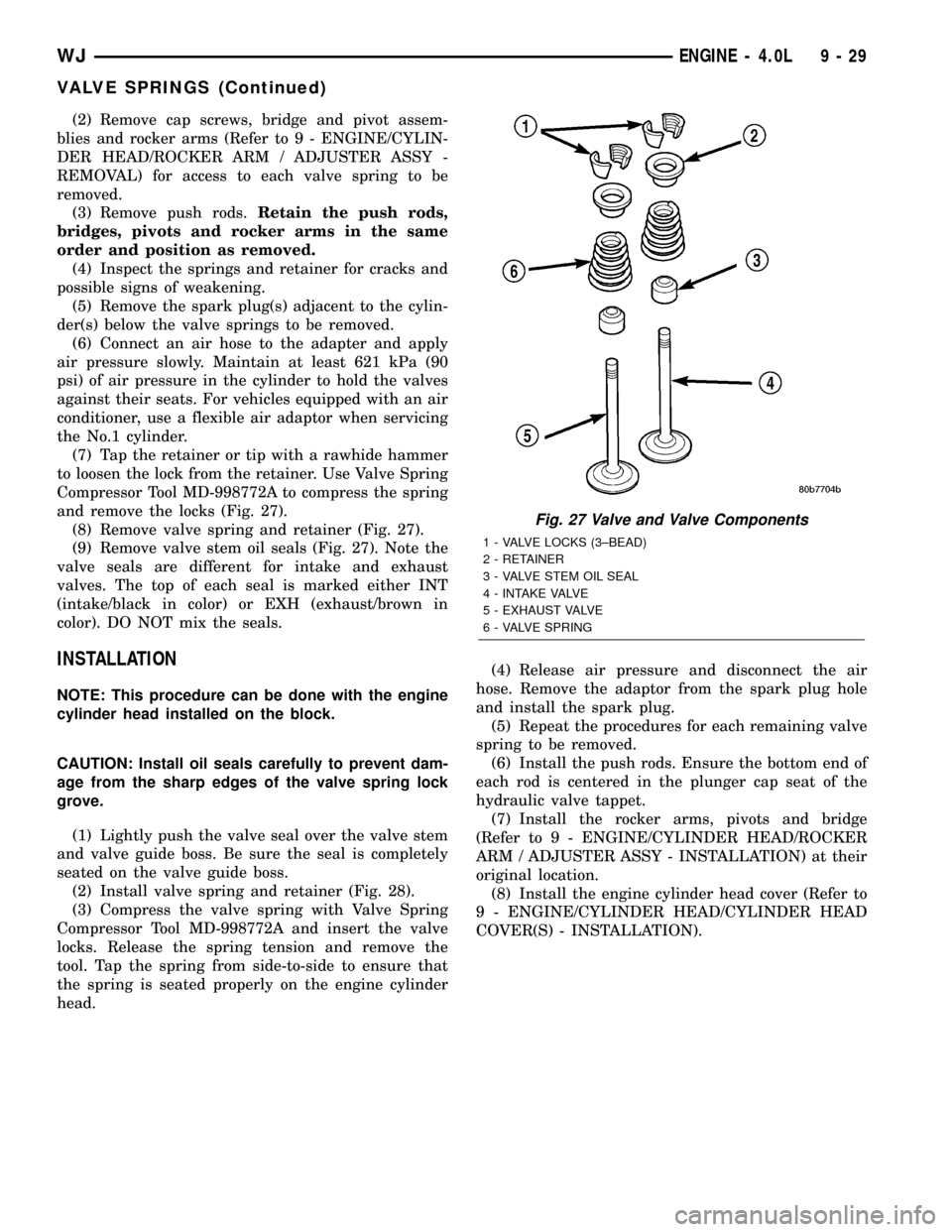
to loosen the lock from the retainer. Use Valve Spring
Compressor Tool MD-998772A to compress the spring
and remove the locks (Fig. 27).
(8) Remove valve spring and retainer (Fig. 27).
(9) Remove valve stem oil seals (Fig. 27). Note the
valve seals are different for intake and exhaust
valves. The top of each seal is marked either INT
(intake/black in color) or EXH (exhaust/brown in
color). DO NOT mix the seals.
INSTALLATION
NOTE: This procedure can be done with the engine
cylinder head installed on the block.
CAUTION: Install oil seals carefully to prevent dam-
age from the sharp edges of the valve spring lock
grove.
(1) Lightly push the valve seal over the valve stem
and valve guide boss. Be sure the seal is completely
seated on the valve guide boss.
(2) Install valve spring and retainer (Fig. 28).
(3) Compress the valve spring with Valve Spring
Compressor Tool MD-998772A and insert the valve
locks. Release the spring tension and remove the
tool. Tap the spring from side-to-side to ensure that
the spring is seated properly on the engine cylinder
head.(4) Release air pressure and disconnect the air
hose. Remove the adaptor from the spark plug hole
and install the spark plug.
(5) Repeat the procedures for each remaining valve
spring to be removed.
(6) Install the push rods. Ensure the bottom end of
each rod is centered in the plunger cap seat of the
hydraulic valve tappet.
(7) Install the rocker arms, pivots and bridge
(Refer to 9 - ENGINE/CYLINDER HEAD/ROCKER
ARM / ADJUSTER ASSY - INSTALLATION) at their
original location.
(8) Install the engine cylinder head cover (Refer to
9 - ENGINE/CYLINDER HEAD/CYLINDER HEAD
COVER(S) - INSTALLATION).
Fig. 27 Valve and Valve Components
1 - VALVE LOCKS (3±BEAD)
2 - RETAINER
3 - VALVE STEM OIL SEAL
4 - INTAKE VALVE
5 - EXHAUST VALVE
6 - VALVE SPRING
WJENGINE - 4.0L 9 - 29
VALVE SPRINGS (Continued)
Page 1286 of 2199
HYDRAULIC LIFTERS
DESCRIPTION
Valve lash is controlled by hydraulic tappets
located inside the cylinder block, in tappet bores
above the camshaft.
REMOVAL
NOTE: Retain all the components in the same order
as removed.
(1) Remove the engine cylinder head(Refer to 9 -
ENGINE/CYLINDER HEAD - REMOVAL).
(2) Remove the push rods.
(3) Remove the tappets through the push rod open-
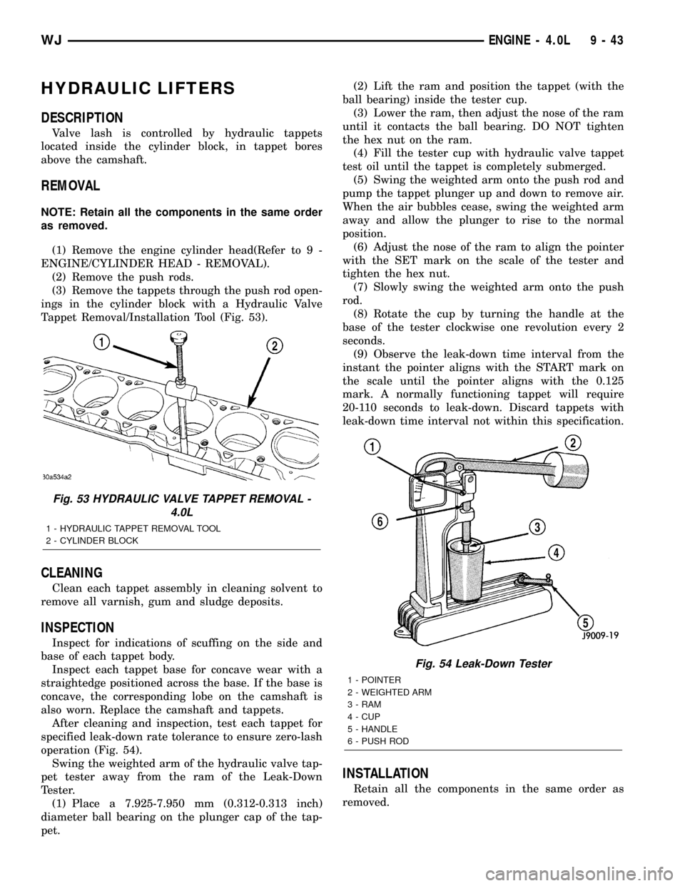
ings in the cylinder block with a Hydraulic Valve
Tappet Removal/Installation Tool (Fig. 53).
CLEANING
Clean each tappet assembly in cleaning solvent to
remove all varnish, gum and sludge deposits.
INSPECTION
Inspect for indications of scuffing on the side and
base of each tappet body.
Inspect each tappet base for concave wear with a
straightedge positioned across the base. If the base is
concave, the corresponding lobe on the camshaft is
also worn. Replace the camshaft and tappets.
After cleaning and inspection, test each tappet for
specified leak-down rate tolerance to ensure zero-lash
operation (Fig. 54).
Swing the weighted arm of the hydraulic valve tap-
pet tester away from the ram of the Leak-Down
Tester.
(1) Place a 7.925-7.950 mm (0.312-0.313 inch)
diameter ball bearing on the plunger cap of the tap-
pet.(2) Lift the ram and position the tappet (with the
ball bearing) inside the tester cup.
(3) Lower the ram, then adjust the nose of the ram
until it contacts the ball bearing. DO NOT tighten
the hex nut on the ram.
(4) Fill the tester cup with hydraulic valve tappet
test oil until the tappet is completely submerged.
(5) Swing the weighted arm onto the push rod and
pump the tappet plunger up and down to remove air.
When the air bubbles cease, swing the weighted arm
away and allow the plunger to rise to the normal
position.
(6) Adjust the nose of the ram to align the pointer
with the SET mark on the scale of the tester and
tighten the hex nut.
(7) Slowly swing the weighted arm onto the push
rod.
(8) Rotate the cup by turning the handle at the
base of the tester clockwise one revolution every 2
seconds.
(9) Observe the leak-down time interval from the
instant the pointer aligns with the START mark on
the scale until the pointer aligns with the 0.125
mark. A normally functioning tappet will require
20-110 seconds to leak-down. Discard tappets with
leak-down time interval not within this specification.
INSTALLATION
Retain all the components in the same order as
removed.
Fig. 53 HYDRAULIC VALVE TAPPET REMOVAL -
4.0L
1 - HYDRAULIC TAPPET REMOVAL TOOL
2 - CYLINDER BLOCK
Fig. 54 Leak-Down Tester
1 - POINTER
2 - WEIGHTED ARM
3 - RAM
4 - CUP
5 - HANDLE
6 - PUSH ROD
WJENGINE - 4.0L 9 - 43