buttons JEEP GRAND CHEROKEE 2003 WJ / 2.G User Guide
[x] Cancel search | Manufacturer: JEEP, Model Year: 2003, Model line: GRAND CHEROKEE, Model: JEEP GRAND CHEROKEE 2003 WJ / 2.GPages: 2199, PDF Size: 76.01 MB
Page 512 of 2199

POWER MIRROR SWITCH
DESCRIPTION
Both the right and left power outside mirrors are
controlled by a single multi-function switch unit
located on the driver side front door trim panel. The
power mirror switch unit includes a three-position
rocker selector switch and four momentary direc-
tional push button switches.
The power mirror switch unit is integral to the
Driver Door Module (DDM). The power mirror switch
cannot be repaired or adjusted and, if faulty or dam-
aged, the entire DDM unit must be replaced. (Refer
to 8 - ELECTRICAL/ELECTRONIC CONTROL
MODULES/DRIVER DOOR MODULE - REMOVAL)
for the DDM service procedures.
OPERATION
The power mirror selector switch is moved right
(right mirror control), left (left mirror control), or
center to turn the power outside mirror system off.
When the selector switch is in the right mirror con-
trol or left mirror control position, one of the four
directional control buttons is depressed to control
movement of the selected mirror up, down, right, or
left. When the selector switch is in the Off position,
depressing any of the directional switches will not
change either mirror position.
See the owner's manual in the vehicle glove box for
more information on the features, use and operation
of the power mirror switches.
SIDEVIEW MIRROR
DESCRIPTION
Mechanically folding, power operated outside rear
view mirrors are standard equipment on this model.
Each power mirror housing contains two electric
motors, two drive mechanisms, an electric heating
grid, the mirror glass case and the mirror glass. One
motor and drive controls mirror up-and-down (verti-
cal) movement, and the other controls right-and-left
(horizontal) movement. If the vehicle is equipped
with the optional memory system, each mirror head
also contains two position potentiometers. One posi-
tion potentiometer monitors the vertical mirror
motor, and the other monitors the horizontal mirror
motor.
An optional driver side automatic dimming mirror
is able to automatically change its reflectance level.
This mirror is controlled by the circuitry of the auto-
matic day/night inside rear view mirror. A thin layer
of electrochromic material between two pieces of con-
ductive glass make up the face of the mirror. (Refer
to 8 - ELECTRICAL/POWER MIRRORS/AUTO-MATIC DAY / NIGHT MIRROR - DESCRIPTION) for
more information on this feature.
The power mirror unit cannot be repaired. Only
the mirror glass and glass case are serviced sepa-
rately. The replacement mirror glass is supplied with
an instruction sheet that details the recommended
replacement procedure. If any other component of the
power mirror unit is faulty or damaged, the entire
power mirror unit must be replaced.
OPERATION
Each of the two outside power mirrors includes two
reversible electric motors that are secured within the
power mirror housing. Each motor moves the mirror
case and glass through an integral drive unit. When
a power mirror motor is supplied with battery cur-
rent and ground, it moves the mirror case and glass
through its drive unit in one direction. When the bat-
tery current and ground feeds to the motor are
reversed, it moves the mirror case and glass in the
opposite direction.
The power mirrors are equipped with a standard
equipment electric heating grid that is applied to the
back of each outside rear view mirror glass. When an
electrical current is passed through the resistor wire
of the heating grid, it warms the mirror glass. (Refer
to 8 - ELECTRICAL/HEATED MIRRORS -
DESCRIPTION) for more information on the opera-
tion of the heated mirrors and the rear window
defogger system.
If the driver side mirror is equipped with the auto-
matic dimming outside mirror option, two photocell
sensors on the inside rear view mirror are used to
monitor light levels and adjust the reflectance of both
the inside and driver side outside mirrors. This
change in reflectance helps to reduce the glare of
headlamps approaching the vehicle from the rear.
(Refer to 8 - ELECTRICAL/POWER MIRRORS/AU-
TOMATIC DAY / NIGHT MIRROR - OPERATION)
for more information on this feature.
If the vehicle is equipped with the optional mem-
ory system, the Driver Door Module (DDM) and the
Passenger Door Module (PDM) store the mirror posi-
tion information as monitored through the mirror
motor position potentiometers. When the memory
system requests a recall of the stored mirror position,
the DDM and the PDM are able to duplicate the
stored mirror positions by moving the mirror motors
until the potentiometer readings match the stored
values.
WJPOWER MIRRORS 8N - 15
Page 523 of 2199

OPERATION
The power lumbar adjuster mechanism includes a
reversible electric motor that is secured to the
inboard side of the seat back panel and is connected
to a worm-drive gearbox. The motor and gearbox
operate the lumbar adjuster mechanism in the center
of the seat back by extending and retracting a cable
that actuates a lever. The action of this lever com-
presses or relaxes a grid of flexible slats. The more
this grid is compressed, the more the slats bow out-
ward against the center of the seat back padding,
providing additional lumbar support.
DIAGNOSIS AND TESTING - POWER LUMBAR
ADJUSTER
Actuate the power lumbar switch to move the
power lumbar adjuster in each direction. The power
lumbar adjuster should move in both directions. It
should be noted that the power lumber adjuster nor-
mally operates very quietly and exhibits little visible
movement. If the power lumbar adjuster fails to oper-
ate in only one direction, move the adjuster a short
distance in the opposite direction and test again to be
certain that the adjuster is not at its travel limit. If
the power lumbar adjuster still fails to operate in
only one direction, refer toDiagnosis and Testing
Power Lumbar Switchin this group. If the power
lumbar adjuster fails to operate in either direction,
perform the following tests. For complete circuit dia-
grams, refer toWiring Diagrams.
(1) Check the power seat circuit breaker in the
junction block. If OK, go to Step 2. If not OK, replace
the faulty power seat circuit breaker.
(2) Check for battery voltage at the power seat cir-
cuit breaker in the junction block. If OK, go to Step
3. If not OK, repair the open fused B(+) circuit to the
fuse in the Power Distribution Center as required.
(3) Remove the outboard seat cushion side shield
from the seat. Disconnect the seat wire harness con-
nector from the power lumbar switch connector
receptacle. Check for battery voltage at the fused
B(+) circuit cavity of the power seat wire harness
connector for the power lumbar switch. If OK, go to
Step 4. If not OK, repair the open fused B(+) circuit
to the power seat circuit breaker in the junction
block as required.
(4) Check for continuity between the ground cir-
cuit cavity of the power seat wire harness connector
for the power lumbar switch and a good ground.
There should be continuity. If OK, go to Step 5. If not
OK, repair the open ground circuit to ground as
required.
(5) Test the power lumbar switch. Refer toDiag-
nosis and Testing Power Lumbar Switchin this
group. If the switch tests OK, test the circuits of the
power seat wire harness between the power lumbaradjuster motor and the power lumbar switch for
shorts or opens. If the circuits check OK, replace the
faulty seat back frame assembly. If the circuits are
not OK, repair the power seat wire harness as
required.
MEMORY SET SWITCH
DESCRIPTION
Vehicles equipped with the memory system have a
memory switch mounted to the driver side front door
trim panel (Fig. 12). This switch is used to set and
recall all of the memory system settings for up to two
drivers. The memory switch is a resistor multiplexed
unit that is hard wired to the Driver Door Module
(DDM), which is also located on the driver side front
door trim panel. The DDM sends out the memory
system set and recall requests to the other electronic
modules over the Programmable Communications
Interface (PCI) data bus.
The memory switch cannot be adjusted or repaired
and, if faulty or damaged, it must be replaced. For
complete circuit diagrams, refer toWiring Diagrams
.
OPERATION
The memory switch has three momentary switch
buttons labeled Set, 1 and 2. The Driver 1 and Driver
2 buttons are back-lit with Light-Emitting Diodes
Fig. 12 WJ/WG MEMORY SELECT/SET SWITCH
1 - DRIVER TRIM PANEL
2 - MEMORY SWITCH
8N - 26 POWER SEAT SYSTEMWJ
LUMBAR MOTOR (Continued)
Page 1446 of 2199

INLET FILTER
REMOVAL
The fuel pump inlet filter (strainer) is located on
the bottom of fuel pump module (Fig. 42). The fuel
pump module is located on top of fuel tank.
The fuel pump inlet filter (strainer) is located on
the bottom of fuel pump module (Fig. 42). The fuel
pump module is located on top of fuel tank.
(1) Remove fuel tank. Refer to Fuel Tank Removal/
Installation.
(2) Remove fuel pump module. Refer to Fuel Pump
Module Removal/Installation.
(3) Remove filter by prying from bottom of module
with 2 screwdrivers. Filter is snapped to module.
(4) Clean bottom of pump module.
INSTALLATION
The fuel pump inlet filter (strainer) is located on
the bottom of fuel pump module (Fig. 42). The fuel
pump module is located on top of fuel tank.
(1) Snap new filter to bottom of module.
(2) Install fuel pump module. Refer to Fuel Pump
Module Removal/Installation.
(3) Install fuel tank. Refer to Fuel Tank Removal/
Installation.
QUICK CONNECT FITTING
DESCRIPTION
Different types of quick-connect fittings are used to
attach various fuel system components, lines and tubes.
These are: a single-tab type, a two-tab type or a plastic
retainer ring type. Some are equipped with safety latch
clips. Some may require the use of a special tool for dis-
connection and removal. Refer to Quick-Connect Fit-
tings Removal/Installation for more information.
CAUTION: The interior components (o-rings, clips)
of quick-connect fittings are not serviced sepa-
rately, but new plastic spacers are available for
some types. If service parts are not available, do
not attempt to repair the damaged fitting or fuel line
(tube). If repair is necessary, replace the complete
fuel line (tube) assembly.
STANDARD PROCEDURE - QUICK-CONNECT
FITTINGS
Also refer to Fuel Tubes/Lines/Hoses and Clamps.
Different types of quick-connect fittings are used to
attach various fuel system components, lines and
tubes. These are: a single-tab type, a two-tab type or
a plastic retainer ring type. Safety latch clips are
used on certain components/lines. Certain fittings
may require use of a special tool for disconnection.
DISCONNECTING
WARNING: THE FUEL SYSTEM IS UNDER A CON-
STANT PRESSURE (EVEN WITH ENGINE OFF).
BEFORE SERVICING ANY FUEL SYSTEM HOSE,
FITTING OR LINE, FUEL SYSTEM PRESSURE MUST
BE RELEASED. REFER TO FUEL SYSTEM PRES-
SURE RELEASE PROCEDURE.
CAUTION: The interior components (o-rings, spac-
ers) of some types of quick-connect fitting are not
serviced separately. If service parts are not avail-
able, do not attempt to repair a damaged fitting or
fuel line. If repair is necessary, replace complete
fuel line assembly.
(1) Perform fuel pressure release procedure. Refer
to Fuel Pressure Release Procedure.
(2) Disconnect negative battery cable from battery.
(3) Clean fitting of any foreign material before dis-
assembly.
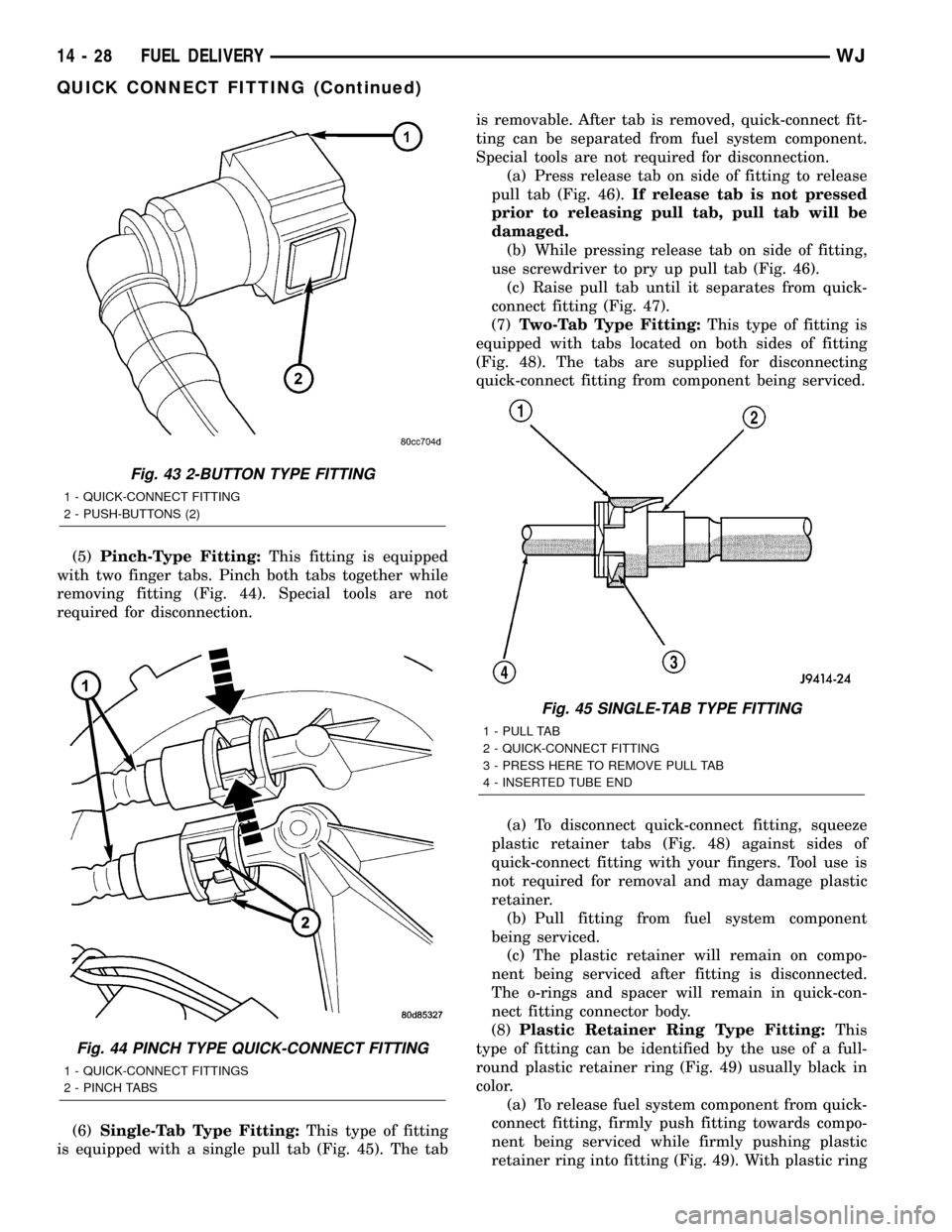
(4)2±Button Type Fitting:This type of fitting is
equipped with a push-button located on each side of
quick-connect fitting (Fig. 43). Press on both buttons
simultaneously for removal. Special tools are not
required for disconnection.
Fig. 42 Fuel Pump Inlet Filter
1 - FUEL PUMP MODULE
2 - FUEL PUMP INLET FILTER
WJFUEL DELIVERY 14 - 27
Page 1447 of 2199

(5)Pinch-Type Fitting:This fitting is equipped
with two finger tabs. Pinch both tabs together while
removing fitting (Fig. 44). Special tools are not
required for disconnection.
(6)Single-Tab Type Fitting:This type of fitting
is equipped with a single pull tab (Fig. 45). The tabis removable. After tab is removed, quick-connect fit-
ting can be separated from fuel system component.
Special tools are not required for disconnection.
(a) Press release tab on side of fitting to release
pull tab (Fig. 46).If release tab is not pressed
prior to releasing pull tab, pull tab will be
damaged.
(b) While pressing release tab on side of fitting,
use screwdriver to pry up pull tab (Fig. 46).
(c) Raise pull tab until it separates from quick-
connect fitting (Fig. 47).
(7)Two-Tab Type Fitting:This type of fitting is
equipped with tabs located on both sides of fitting
(Fig. 48). The tabs are supplied for disconnecting
quick-connect fitting from component being serviced.
(a) To disconnect quick-connect fitting, squeeze
plastic retainer tabs (Fig. 48) against sides of
quick-connect fitting with your fingers. Tool use is
not required for removal and may damage plastic
retainer.
(b) Pull fitting from fuel system component
being serviced.
(c) The plastic retainer will remain on compo-
nent being serviced after fitting is disconnected.
The o-rings and spacer will remain in quick-con-
nect fitting connector body.
(8)Plastic Retainer Ring Type Fitting:This
type of fitting can be identified by the use of a full-
round plastic retainer ring (Fig. 49) usually black in
color.
(a) To release fuel system component from quick-
connect fitting, firmly push fitting towards compo-
nent being serviced while firmly pushing plastic
retainer ring into fitting (Fig. 49). With plastic ring
Fig. 43 2-BUTTON TYPE FITTING
1 - QUICK-CONNECT FITTING
2 - PUSH-BUTTONS (2)
Fig. 44 PINCH TYPE QUICK-CONNECT FITTING
1 - QUICK-CONNECT FITTINGS
2 - PINCH TABS
Fig. 45 SINGLE-TAB TYPE FITTING
1 - PULL TAB
2 - QUICK-CONNECT FITTING
3 - PRESS HERE TO REMOVE PULL TAB
4 - INSERTED TUBE END
14 - 28 FUEL DELIVERYWJ
QUICK CONNECT FITTING (Continued)
Page 2095 of 2199

Both the manual A/C Heater control panel and the
AZC control panel are serviced only as complete
units and cannot be repaired. If faulty or damaged,
the entire control panel unit must be replaced.
DIAGNOSIS AND TESTING - AUTOMATIC ZONE
CONTROL SYSTEM
The Automatic Zone Control (AZC) control module
has a system self-diagnostic mode which continuously
monitors various parameters during normal system
operation. If a system fault is detected, a current and
historical fault is recorded. When the current fault is
cleared, the historical fault remains until reset (man-
ually or automatically). Both the current and histor-
ical fault codes can be accessed through either the
front panel, or over the Programmable Communica-
tions Interface (PCI) bus using a DRBIIItscan tool,
and the appropriate diagnostic information.
The AZC control module is capable of three differ-
ent types of self-diagnostic tests, as follows:
²Fault Code Tests
²Input Circuit Tests
²Output Circuit/Actuator Tests
The information that follows describes:
²How to read the self-diagnostic display
²How to enter the AZC control module self-diag-
nostic test mode
²How to select the self-diagnostic test types
²How to perform the different tests
ENTERING THE AZC SELF-DIAGNOSTIC MODE
To enter the AZC self-diagnostic mode, perform the
following:
(1) Depress the a/c and recirc buttons at the same
time and hold. Rotate the left temperature control
knob clockwise (CW) one detent.
(2) If you continue to keep the a/c and recirc but-
tons depressed, the AZC control module will perform
a Segment Test of the Vacuum Fluorescent (VF) dis-
play. In the Segment Test you should see all of the
display segments illuminate as long as both buttons
are held. If a display segment fails to illuminate, the
vacuum fluorescent display is faulty and the a/c
heater control must be replaced.
(3) After viewing the Segment Test, release the
A/C and Recirc buttons and the display will clear
momentarily.Ifa0isdisplayed, then no faults
are set in the system.Should there be any faults,
either9current9or9historical9, all fault codes will be
displayed in ascending numerical sequence (note no
effort is made to display fault codes in chronological
order). Each fault code is displayed for one second
before the next code is displayed. Once all fault codes
have been displayed, the system will then repeat the
fault code numbers. This will continue until the left
side set temperature control is moved at least onedetent position in the CW direction or the ignition is
turned9OFF9.
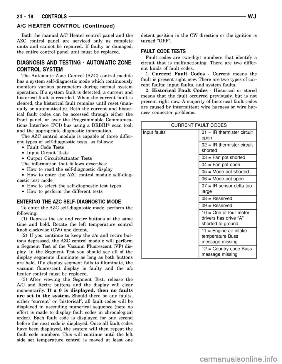
FAULT CODE TESTS
Fault codes are two-digit numbers that identify a
circuit that is malfunctioning. There are two differ-
ent kinds of fault codes.
1.Current Fault Codes- Current means the
fault is present right now. There are two types of cur-
rent faults: input faults, and system faults.
2.Historical Fault Codes- Historical or stored
means that the fault occurred previously, but is not
present right now. A majority of historical fault codes
are caused by intermittent wire harness or wire har-
ness connector problems.
CURRENT FAULT CODES
Input faults 01 = IR thermister circuit
open
02 = IR thermister circuit
shorted
03 = Fan pot shorted
04 = Fan pot open
05 = Mode pot shorted
06 = Mode pot open
07 = IR sensor delta too
large
08 = Reserved
09 = Reserved
10 = One of four motor
drivers has drive9A9
shorted to ground
11 = Engine air intake
temperature Buss
message missing
12 = Country code Buss
message missing
24 - 18 CONTROLSWJ
A/C HEATER CONTROL (Continued)
Page 2097 of 2199

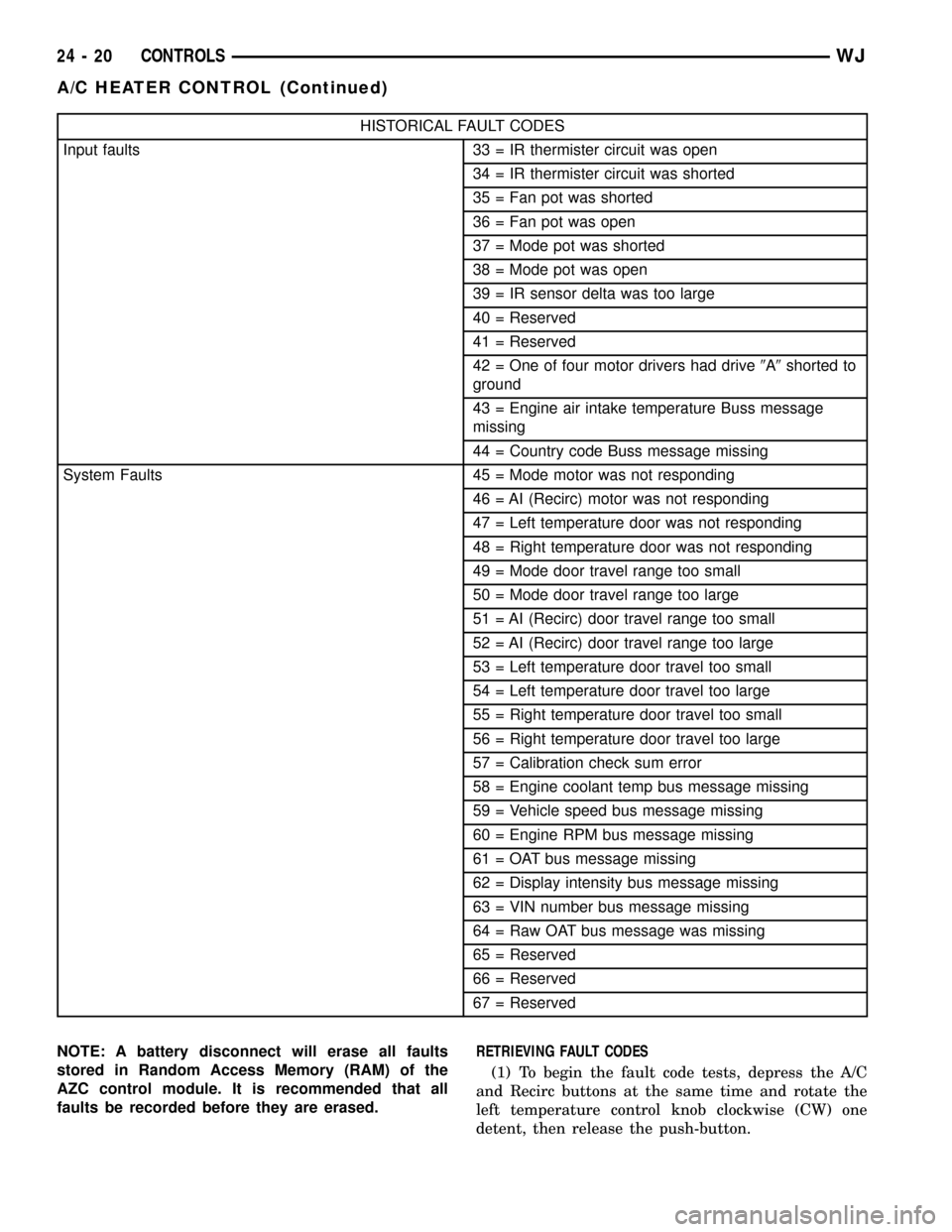
HISTORICAL FAULT CODES
Input faults 33 = IR thermister circuit was open
34 = IR thermister circuit was shorted
35 = Fan pot was shorted
36 = Fan pot was open
37 = Mode pot was shorted
38 = Mode pot was open
39 = IR sensor delta was too large
40 = Reserved
41 = Reserved
42 = One of four motor drivers had drive9A9shorted to
ground
43 = Engine air intake temperature Buss message
missing
44 = Country code Buss message missing
System Faults 45 = Mode motor was not responding
46 = AI (Recirc) motor was not responding
47 = Left temperature door was not responding
48 = Right temperature door was not responding
49 = Mode door travel range too small
50 = Mode door travel range too large
51 = AI (Recirc) door travel range too small
52 = AI (Recirc) door travel range too large
53 = Left temperature door travel too small
54 = Left temperature door travel too large
55 = Right temperature door travel too small
56 = Right temperature door travel too large
57 = Calibration check sum error
58 = Engine coolant temp bus message missing
59 = Vehicle speed bus message missing
60 = Engine RPM bus message missing
61 = OAT bus message missing
62 = Display intensity bus message missing
63 = VIN number bus message missing
64 = Raw OAT bus message was missing
65 = Reserved
66 = Reserved
67 = Reserved
NOTE: A battery disconnect will erase all faults
stored in Random Access Memory (RAM) of the
AZC control module. It is recommended that all
faults be recorded before they are erased.RETRIEVING FAULT CODES
(1) To begin the fault code tests, depress the A/C
and Recirc buttons at the same time and rotate the
left temperature control knob clockwise (CW) one
detent, then release the push-button.
24 - 20 CONTROLSWJ
A/C HEATER CONTROL (Continued)
Page 2098 of 2199

(2)If there are no fault codes, the ª00º dis-
play value will remain in the VF window.Should
there be any codes, each will be displayed for one
second in ascending numerical sequence (note: no
effort is made to display faults in the order they
occurred). The left side set temperature display will
be blanked and the right side set temperature dis-
play will indicate current and historical codes (8 his-
torical max) presently active. Once all codes have
been displayed, the system will repeat the fault code
numbers. This will continue until the left side set
temperature control is moved at least one detent
position in either direction, by pressing both the A/C
and Recirc buttons at the same time, or the ignition
is turned off. Record all of the fault codes, then see
the Current and Historical Fault Code charts for the
descriptions.
CLEARING FAULT CODES
Current faults cannot be electronically cleared.
Repair must be made to the system to eliminate the
fault causing code. Historical fault codes can be
cleared manually, or automatically. To clear a histor-
ical fault manually, depress and hold either the A/C
or Recirc button for at least three seconds while the
display is in the fault code mode of operation. Histor-
ical fault codes are cleared automatically when the
corresponding current fault code has been cleared,
and has remained cleared for a number of ignition
cycles. The faults have been cleared when two hori-
zontal bars appear in the Test Selector display.
EXITING SELF-DIAGNOSTIC MODE
The self-diagnostic mode can be exited by pressing
both the A/C and Recirc buttons at the same time, or
turning off the ignition.
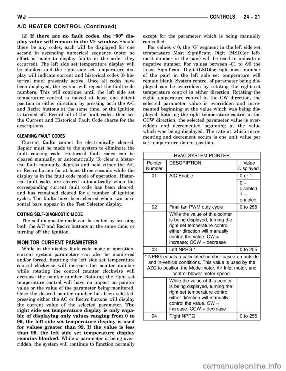
MONITOR CURRENT PARAMETERS
While in the display fault code mode of operation,
current system parameters can also be monitored
and/or forced. Rotating the left side set temperature
control clockwise will increase the pointer number
while rotating the control counter clockwise will
decrease the pointer number. Rotating the right set
temperature control will have no impact on pointer
value or the value of the parameter being monitored.
Once the desired pointer number has been selected,
pressing either the AC or Recirc buttons will display
the current value of the selected parameter.The
right side set temperature display is only capa-
ble of displaying only values ranging from 0 to
99, the left side set temperature display is used
for values greater than 99. If the value is less
than 99, the left side set temperature display
remains blanked.While a parameter is being over-
ridden, the system will continue to function normallyexcept for the parameter which is being manually
controlled.
For values < 0, the9G9segment in the left side set
temperature Most Significant Digit (MSD)(or left-
most number in the pair) will be used to indicate a
negative number. For values between -01 to -99 the
Least Significant Digit (LSD)(or right-most number
of the pair) in the left side set temperature will
remain blank. System control of parameter being dis-
played can be overridden by rotating the right set
temperature control in either direction. Rotating the
right temperature control in the CW direction, the
selected parameter value is overridden and incre-
mented beginning at the value which was being dis-
played. Rotating the right temperature control in the
CCW direction, the selected parameter value is over-
ridden and decremented beginning at the value
which was being displayed. The rate at which incre-
menting and decrement occurs is one unit value per
set temperature detent position.
HVAC SYSTEM POINTER
Pointer
NumberDESCRIPTION Value
Displayed
01 A/C Enable 0 or 1
0=
disabled
1=
enabled
02 Final fan PWM duty cycle 0 to 255
While the value of this pointer
is being displayed, turning the
right set temperature control
either direction will manually
control the value. CW =
increase; CCW = decrease
03 Left NPRG * 0 to 255
* NPRG equals a calculated number based on outside
and in-vehicle conditions. This value is used by the
AZC to position the Mode motor, Air Inlet motor, and
control blower motor speed.
While the value of this pointer
is being displayed, turning the
right set temperature control
either direction will manually
control the value. CW =
increase; CCW = decrease
04 Right NPRG 0 to 255
WJCONTROLS 24 - 21
A/C HEATER CONTROL (Continued)