diesel engine JEEP GRAND CHEROKEE 2003 WJ / 2.G User Guide
[x] Cancel search | Manufacturer: JEEP, Model Year: 2003, Model line: GRAND CHEROKEE, Model: JEEP GRAND CHEROKEE 2003 WJ / 2.GPages: 2199, PDF Size: 76.01 MB
Page 450 of 2199
ing the system voltage is high (system voltage is
about sixteen volts or higher), the gauge needle is
moved to the relative voltage position in the red zone
of the gauge scale and the check gauges indicator is
illuminated. The gauge needle remains in the red
zone and the check gauges indicator remains illumi-
nated until the cluster receives a message from the
PCM indicating there is no high system voltage con-
dition (system voltage is below about sixteen volts,
but higher than about eleven volts).
²Communication Error- If the cluster fails to
receive a system voltage message, it will hold the
gauge needle at the last indication for about twelve
seconds, until a new message is received, or until the
ignition switch is turned to the Off position, which-
ever occurs first. After twelve seconds, the cluster
will return the gauge needle to the low end of the
gauge scale.
²Actuator Test- Each time the cluster is put
through the actuator test, the gauge needle will be
swept across the entire gauge scale and back to con-
firm the functionality of the gauge and the cluster
control circuitry.
The PCM continually monitors the system voltage
to control the generator output. The PCM then sends
the proper system voltage messages to the instru-
ment cluster. For further diagnosis of the voltage
gauge or the instrument cluster circuitry that con-
trols the gauge, (Refer to 8 - ELECTRICAL/INSTRU-
MENT CLUSTER - DIAGNOSIS AND TESTING). If
the instrument cluster turns on the check gauges
indicator due to a system voltage low or high condi-
tion, it may indicate that the charging system
requires service. For proper diagnosis of the charging
system, the PCI data bus, or the electronic message
inputs to the instrument cluster that control the volt-
age gauge, a DRBIIItscan tool is required. Refer to
the appropriate diagnostic information.
WAIT-TO-START INDICATOR
DESCRIPTION
A wait-to-start indicator is only found in the
instrument clusters of vehicles equipped with an
optional diesel engine. The wait-to-start indicator is
located near the lower edge of the tachometer gauge
dial face, to the right of center. The wait-to-start
indicator consists of an International Control and
Display Symbol icon for ªDiesel Preheatº imprinted
on an amber lens. The lens is located behind a cutout
in the opaque layer of the tachometer gauge dial face
overlay. The dark outer layer of the gauge dial face
overlay prevents the icon from being clearly visible
when the indicator is not illuminated. The icon
appears silhouetted against an amber field throughthe translucent outer layer of the gauge dial face
overlay when the indicator is illuminated from
behind by a replaceable incandescent bulb and bulb
holder unit located on the instrument cluster elec-
tronic circuit board. The wait-to-start indicator lens
is serviced as a unit with the instrument cluster.
OPERATION
The wait-to-start indicator gives an indication to
the vehicle operator when the diesel engine glow
plugs are energized in their preheat operating mode.
This indicator is controlled by a transistor on the
instrument cluster circuit board based upon cluster
programming and electronic messages received by
the cluster from the Powertrain Control Module
(PCM) over the Programmable Communications
Interface (PCI) data bus. The wait-to-start indicator
bulb is completely controlled by the instrument clus-
ter logic circuit, and that logic will only allow this
indicator to operate when the instrument cluster
receives a battery current input on the fused ignition
switch output (run-start) circuit. Therefore, the indi-
cator will always be off when the ignition switch is in
any position except On or Start. The bulb only illu-
minates when it is switched to ground by the instru-
ment cluster transistor. The instrument cluster will
turn on the wait-to-start indicator for the following
reasons:
²Wait-To-Start Indicator Lamp-On Message-
Each time the cluster receives a wait-to-start indica-
tor lamp-on message from the PCM indicating the
glow plugs are heating and the driver must wait to
start the engine, the wait-to-start indicator will be
illuminated. The indicator remains illuminated until
the cluster receives a wait-to-start indicator lamp-off
message, or until the ignition switch is turned to the
Off position, whichever occurs first.
²Actuator Test- Each time the cluster is put
through the actuator test, the wait-to-start indicator
will be turned on for the duration of the test to con-
firm the functionality of the bulb and the cluster con-
trol circuitry.
The PCM continually monitors the ambient tem-
perature and the glow plug pre-heater circuits to
determine how long the glow plugs must be heated in
the pre-heat operating mode. The PCM then sends
the proper wait-to-start indicator lamp-on and lamp-
off messages to the instrument cluster. If the wait-to-
start indicator fails to light during the actuator test,
replace the bulb with a known good unit. For further
diagnosis of the wait-to-start indicator or the instru-
ment cluster circuitry that controls the indicator,
(Refer to 8 - ELECTRICAL/INSTRUMENT CLUS-
TER - DIAGNOSIS AND TESTING). For proper
diagnosis of the glow plug pre-heater control circuits,
the PCM, the PCI data bus, or the electronic message
WJINSTRUMENT CLUSTER 8J - 35
VOLTAGE GAUGE (Continued)
Page 451 of 2199
inputs to the instrument cluster that control the
wait-to-start indicator, a DRBIIItscan tool is
required. Refer to the appropriate diagnostic infor-
mation.
WATER-IN-FUEL INDICATOR
DESCRIPTION
A water-in-fuel indicator is only found in the
instrument clusters of vehicles equipped with an
optional diesel engine. The water-in-fuel indicator is
located near the left edge of the instrument cluster,
to the left of the tachometer. The water-in-fuel indi-
cator consists of an International Control and Dis-
play Symbol icon for ªWater in Fuelº imprinted on a
red lens. The lens is located behind a cutout in the
opaque layer of the instrument cluster overlay. The
dark outer layer of the overlay prevents the icon
from being clearly visible when the indicator is not
illuminated. The icon appears silhouetted against a
red field through the translucent outer layer of the
overlay when the indicator is illuminated from
behind by a Light Emitting Diode (LED), which is
soldered onto the instrument cluster electronic circuit
board. The water-in-fuel indicator lens is serviced as
a unit with the instrument cluster lens, hood and
mask unit.
OPERATION
The water-in-fuel indicator gives an indication to
the vehicle operator when there is excessive water in
the fuel system. This indicator is controlled by a
transistor on the instrument cluster circuit board
based upon cluster programming and electronic mes-
sages received by the cluster from the Powertrain
Control Module (PCM) over the Programmable Com-
munications Interface (PCI) data bus. The water-in-
fuel indicator Light Emitting Diode (LED) is
completely controlled by the instrument cluster logic
circuit, and that logic will only allow this indicator tooperate when the instrument cluster receives a bat-
tery current input on the fused ignition switch out-
put (run-start) circuit. Therefore, the indicator will
always be off when the ignition switch is in any posi-
tion except On or Start. The LED only illuminates
when it is provided a path to ground by the instru-
ment cluster transistor. The instrument cluster will
turn on the water-in-fuel indicator for the following
reasons:
²Bulb Test- Each time the ignition switch is
turned to the On position the water-in-fuel indicator
is illuminated for about three seconds as a bulb test.
²Water-In-Fuel Indicator Lamp-On Message-
Each time the cluster receives a water-in-fuel indica-
tor lamp-on message from the PCM indicating there
is excessive water in the diesel fuel system, the
water-in-fuel indicator will be illuminated. The indi-
cator remains illuminated until the cluster receives a
water-in-fuel indicator lamp-off message, or until the
ignition switch is turned to the Off position, which-
ever occurs first.
²Actuator Test- Each time the cluster is put
through the actuator test, the water-in-fuel indicator
will be turned on for the duration of the test to con-
firm the functionality of the LED and the cluster con-
trol circuitry.
The PCM continually monitors the water-in-fuel
sensor to determine whether there is excessive water
in the diesel fuel. The PCM then sends the proper
water-in-fuel indicator lamp-on and lamp-off mes-
sages to the instrument cluster. For further diagnosis
of the water-in-fuel indicator or the instrument clus-
ter circuitry that controls the indicator, (Refer to 8 -
ELECTRICAL/INSTRUMENT CLUSTER - DIAGNO-
SIS AND TESTING). For proper diagnosis of the
water-in-fuel sensor, the PCM, the PCI data bus, or
the electronic message inputs to the instrument clus-
ter that control the water-in-fuel indicator, a
DRBIIItscan tool is required. Refer to the appropri-
ate diagnostic information.
8J - 36 INSTRUMENT CLUSTERWJ
WAIT-TO-START INDICATOR (Continued)
Page 1050 of 2199
Component Page
DRIVER SEAT BELT SWITCH........ 8W-80-74
DRIVER SIDE IMPACT SENSOR...... 8W-80-74
EGR SOLENOID (DIESEL)........... 8W-80-74
ELECTRIC BRAKE
(EXCEPT BUILT-UP-EXPORT)...... 8W-80-74
ELECTRONIC SPEED CONTROL
SERVO ......................... 8W-80-74
ENGINE CONTROL MODULE C1
(DIESEL)....................... 8W-80-75
ENGINE CONTROL MODULE C2
(DIESEL)....................... 8W-80-76
ENGINE COOLANT TEMPERATURE
SENSOR (DIESEL)................ 8W-80-77
ENGINE COOLANT TEMPERATURE
SENSOR (GAS)................... 8W-80-77
ENGINE OIL PRESSURE
SENSOR (DIESEL)................ 8W-80-77
ENGINE OIL PRESSURE
SENSOR (GAS)................... 8W-80-78
EVAP/PURGE SOLENOID (GAS)....... 8W-80-78
FRONT POWER OUTLET............ 8W-80-78
FRONT WASHER PUMP............. 8W-80-78
FRONT WIPER MOTOR............. 8W-80-78
FUEL INJECTOR NO. 1 (DIESEL)..... 8W-80-79
FUEL INJECTOR NO. 1 (GAS)........ 8W-80-79
FUEL INJECTOR NO. 2 (DIESEL)..... 8W-80-79
FUEL INJECTOR NO. 2 (GAS)........ 8W-80-79
FUEL INJECTOR NO. 3 (DIESEL)..... 8W-80-79
FUEL INJECTOR NO. 3 (GAS)........ 8W-80-80
FUEL INJECTOR NO. 4 (DIESEL)..... 8W-80-80
FUEL INJECTOR NO. 4 (GAS)........ 8W-80-80
FUEL INJECTOR NO. 5 (DIESEL)..... 8W-80-80
FUEL INJECTOR NO. 5 (GAS)........ 8W-80-81
FUEL INJECTOR NO. 6 (GAS)........ 8W-80-81
FUEL INJECTOR NO. 7 (4.7L)........ 8W-80-81
FUEL INJECTOR NO. 8 (4.7L)........ 8W-80-81
FUEL PRESSURE SENSOR (DIESEL) . . 8W-80-82
FUEL PRESSURE SOLENOID
(DIESEL)....................... 8W-80-82
FUEL PUMP MODULE (GAS)......... 8W-80-82
FUEL TANK MODULE (DIESEL)...... 8W-80-82
GENERATOR (DIESEL).............. 8W-80-82
GENERATOR (GAS)................. 8W-80-83
GLOVE BOX LAMP................. 8W-80-83
HEADLAMP LEVELING SWITCH
(BUILT-UP-EXPORT).............. 8W-80-83
HOOD AJAR SWITCH
(BUILT-UP-EXPORT).............. 8W-80-83
HORN NO. 1....................... 8W-80-83
HORN NO. 2....................... 8W-80-84
HYDRAULIC COOLING MODULE..... 8W-80-84
IDLE AIR CONTROL MOTOR......... 8W-80-84
IGNITION SWITCH C1.............. 8W-80-84
IGNITION SWITCH C2.............. 8W-80-84
INPUT SPEED SENSOR (4.7L)........ 8W-80-85Component Page
INSTRUMENT CLUSTER............ 8W-80-85
INTAKE AIR TEMPERATURE
SENSOR (DIESEL)................ 8W-80-85
INTAKE AIR TEMPERATURE
SENSOR (GAS)................... 8W-80-85
INTAKE PORT SWIRL ACTUATOR
(DIESEL)....................... 8W-80-86
INTRUSION TRANSCEIVER MODULE
(BUILT-UP-EXPORT).............. 8W-80-86
JUNCTION BLOCK BODY
CONTROL MODULE.............. 8W-80-86
JUNCTION BLOCK C1.............. 8W-80-87
JUNCTION BLOCK C2 (LHD)......... 8W-80-88
JUNCTION BLOCK C2 (RHD)......... 8W-80-89
JUNCTION BLOCK C3.............. 8W-80-90
JUNCTION BLOCK C4.............. 8W-80-91
JUNCTION BLOCK C5.............. 8W-80-91
KNOCK SENSOR................... 8W-80-91
LEAK DETECTION PUMP (EXCEPT
BUILT-UP-EXPORT)............... 8W-80-91
LEFT COURTESY LAMP............. 8W-80-91
LEFT DOOR HANDLE COURTESY
LAMP.......................... 8W-80-92
LEFT FOG LAMP................... 8W-80-92
LEFT FRONT DOOR SPEAKER....... 8W-80-92
LEFT FRONT IMPACT SENSOR....... 8W-80-92
LEFT FRONT PARK LAMP........... 8W-80-92
LEFT FRONT PARK/TURN SIGNAL LAMP
(EXCEPT BUILT-UP-EXPORT)...... 8W-80-93
LEFT FRONT SIDE MARKER LAMP
(EXCEPT BUILT-UP-EXPORT)...... 8W-80-93
LEFT FRONT TURN SIGNAL LAMP
(BUILT-UP-EXPORT).............. 8W-80-93
LEFT FRONT WHEEL SPEED
SENSOR........................ 8W-80-93
LEFT HEADLAMP LEVELING MOTOR
(BUILT-UP-EXPORT).............. 8W-80-94
LEFT HIGH BEAM HEADLAMP....... 8W-80-94
LEFT INSTRUMENT PANEL SPEAKER . 8W-80-94
LEFT LIFTGATE AJAR SWITCH....... 8W-80-94
LEFT LOW BEAM HEADLAMP....... 8W-80-94
LEFT MULTI-FUNCTION SWITCH.... 8W-80-95
LEFT REAR DOOR LOCK
MOTOR/AJAR SWITCH............ 8W-80-95
LEFT REAR DOOR SPEAKER......... 8W-80-95
LEFT REAR LAMP ASSEMBLY........ 8W-80-95
LEFT REAR WHEEL SPEED
SENSOR........................ 8W-80-96
LEFT REMOTE RADIO SWITCH...... 8W-80-96
LEFT SIDE REPEATER LAMP
(BUILT-UP-EXPORT).............. 8W-80-96
LEFT VISOR/VANITY LAMP.......... 8W-80-96
LICENSE LAMP NO. 1.............. 8W-80-96
LICENSE LAMP NO. 2.............. 8W-80-97
LIFTGATE FLIP-UP AJAR SWITCH.... 8W-80-97
WJ8W-80 CONNECTOR PIN-OUT 8W - 80 - 3
Page 1059 of 2199
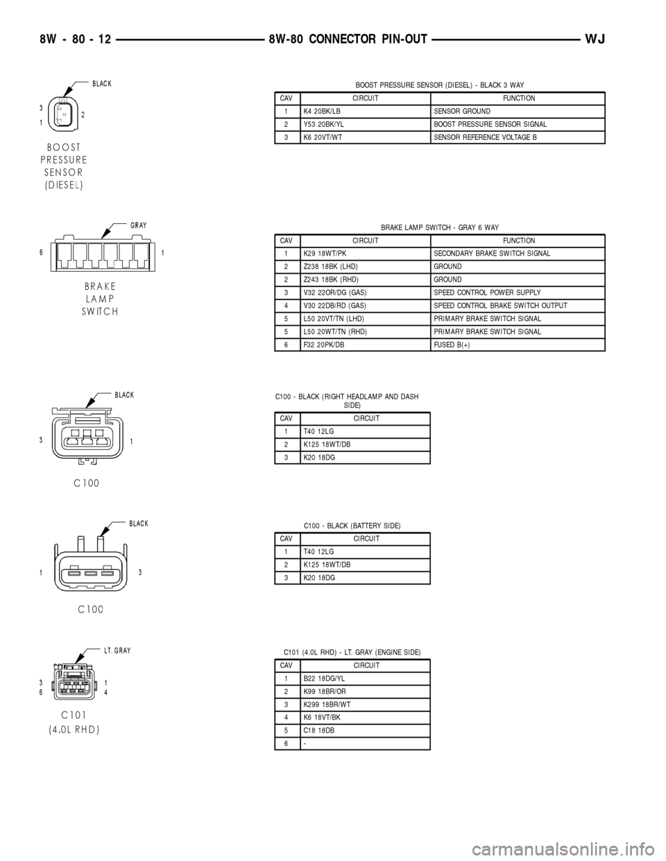
BOOST PRESSURE SENSOR (DIESEL) - BLACK 3 WAY
CAV CIRCUIT FUNCTION
1 K4 20BK/LB SENSOR GROUND
2 Y53 20BK/YL BOOST PRESSURE SENSOR SIGNAL
3 K6 20VT/WT SENSOR REFERENCE VOLTAGE B
BRAKE LAMP SWITCH - GRAY 6 WAY
CAV CIRCUIT FUNCTION
1 K29 18WT/PK SECONDARY BRAKE SWITCH SIGNAL
2 Z238 18BK (LHD) GROUND
2 Z243 18BK (RHD) GROUND
3 V32 22OR/DG (GAS) SPEED CONTROL POWER SUPPLY
4 V30 22DB/RD (GAS) SPEED CONTROL BRAKE SWITCH OUTPUT
5 L50 20VT/TN (LHD) PRIMARY BRAKE SWITCH SIGNAL
5 L50 20WT/TN (RHD) PRIMARY BRAKE SWITCH SIGNAL
6 F32 20PK/DB FUSED B(+)
C100 - BLACK (RIGHT HEADLAMP AND DASH
SIDE)
CAV CIRCUIT
1 T40 12LG
2 K125 18WT/DB
3 K20 18DG
C100 - BLACK (BATTERY SIDE)
CAV CIRCUIT
1 T40 12LG
2 K125 18WT/DB
3 K20 18DG
C101 (4.0L RHD) - LT. GRAY (ENGINE SIDE)
CAV CIRCUIT
1 B22 18DG/YL
2 K99 18BR/OR
3 K299 18BR/WT
4 K6 18VT/BK
5 C18 18DB
6-
8W - 80 - 12 8W-80 CONNECTOR PIN-OUTWJ
Page 1061 of 2199
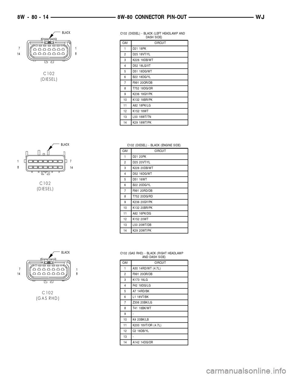
C102 (DIESEL) - BLACK (LEFT HEADLAMP AND
DASH SIDE)
CAV CIRCUIT
1 D21 18PK
2 D25 18VT/YL
3 K226 18DB/WT
4 D52 18LG/VT
5 D51 18DG/WT
6 B22 18DG/YL
7 F991 20OR/DB
8 T752 18DG/OR
9 K236 18GY/PK
10 K132 18BR/PK
11 A82 18PK/LG
12 K152 18WT
13 L50 18WT/TN
14 K29 18WT/PK
C102 (DIESEL) - BLACK (ENGINE SIDE)
CAV CIRCUIT
1 D21 20PK
2 D25 20VT/YL
3 K226 20DB/WT
4 D52 16DG/WT
5 D51 16WT
6 B22 20DG/YL
7 F991 20RD/DB
8 T752 20DG/RD
9 K236 20GY/PK
10 K132 20BR/PK
11 A82 16PK/DG
12 K152 20WT
13 L50 20WT/DB
14 K29 20WT/PK
C102 (GAS RHD) - BLACK (RIGHT HEADLAMP
AND DASH SIDE)
CAV CIRCUIT
1 A30 14RD/WT (4.7L)
2 F991 20OR/DB
3 K173 18LG
4 F42 18DG/LG
5 A7 14RD/BK
6 L1 18VT/BK
7 Z306 20BK/LG
8 T41 18BK/WT
9-
10 K4 20BK/LB
11 K200 18VT/OR (4.7L)
12 C2 18DB/YL
13 -
14 A142 14DG/OR
8W - 80 - 14 8W-80 CONNECTOR PIN-OUTWJ
Page 1062 of 2199
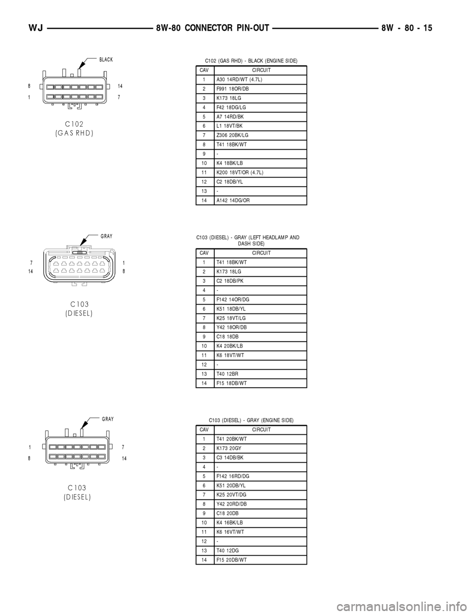
C102 (GAS RHD) - BLACK (ENGINE SIDE)
CAV CIRCUIT
1 A30 14RD/WT (4.7L)
2 F991 18OR/DB
3 K173 18LG
4 F42 18DG/LG
5 A7 14RD/BK
6 L1 18VT/BK
7 Z306 20BK/LG
8 T41 18BK/WT
9-
10 K4 18BK/LB
11 K200 18VT/OR (4.7L)
12 C2 18DB/YL
13 -
14 A142 14DG/OR
C103 (DIESEL) - GRAY (LEFT HEADLAMP AND
DASH SIDE)
CAV CIRCUIT
1 T41 18BK/WT
2 K173 18LG
3 C2 18DB/PK
4-
5 F142 14OR/DG
6 K51 18DB/YL
7 K25 18VT/LG
8 Y42 18OR/DB
9 C18 18DB
10 K4 20BK/LB
11 K6 18VT/WT
12 -
13 T40 12BR
14 F15 18DB/WT
C103 (DIESEL) - GRAY (ENGINE SIDE)
CAV CIRCUIT
1 T41 20BK/WT
2 K173 20GY
3 C3 14DB/BK
4-
5 F142 16RD/DG
6 K51 20DB/YL
7 K25 20VT/DG
8 Y42 20RD/DB
9 C18 20DB
10 K4 16BK/LB
11 K6 16VT/WT
12 -
13 T40 12DG
14 F15 20DB/WT
WJ8W-80 CONNECTOR PIN-OUT 8W - 80 - 15
Page 1064 of 2199
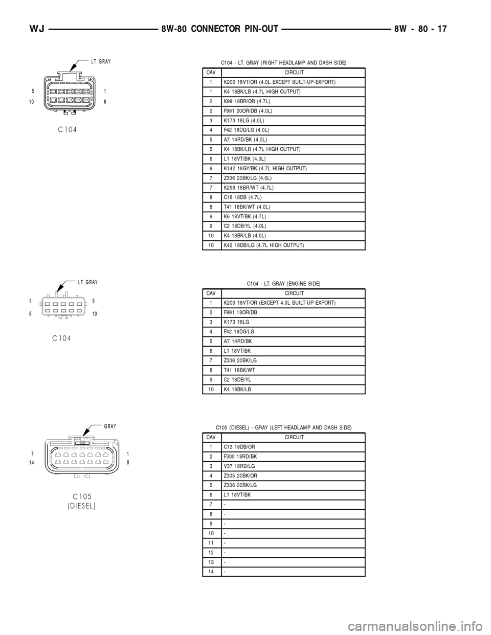
C104 - LT. GRAY (RIGHT HEADLAMP AND DASH SIDE)
CAV CIRCUIT
1 K200 18VT/OR (4.0L EXCEPT BUILT-UP-EXPORT)
1 K4 18BK/LB (4.7L HIGH OUTPUT)
2 K99 18BR/OR (4.7L)
2 F991 20OR/DB (4.0L)
3 K173 18LG (4.0L)
4 F42 18DG/LG (4.0L)
5 A7 14RD/BK (4.0L)
5 K4 18BK/LB (4.7L HIGH OUTPUT)
6 L1 18VT/BK (4.0L)
6 K142 18GY/BK (4.7L HIGH OUTPUT)
7 Z306 20BK/LG (4.0L)
7 K299 18BR/WT (4.7L)
8 C18 18DB (4.7L)
8 T41 18BK/WT (4.0L)
9 K6 18VT/BK (4.7L)
9 C2 18DB/YL (4.0L)
10 K4 18BK/LB (4.0L)
10 K42 18DB/LG (4.7L HIGH OUTPUT)
C104 - LT. GRAY (ENGINE SIDE)
CAV CIRCUIT
1 K200 18VT/OR (EXCEPT 4.0L BUILT-UP-EXPORT)
2 F991 18OR/DB
3 K173 18LG
4 F42 18DG/LG
5 A7 14RD/BK
6 L1 18VT/BK
7 Z306 20BK/LG
8 T41 18BK/WT
9 C2 18DB/YL
10 K4 18BK/LB
C105 (DIESEL) - GRAY (LEFT HEADLAMP AND DASH SIDE)
CAV CIRCUIT
1 C13 18DB/OR
2 F300 18RD/BK
3 V37 18RD/LG
4 Z305 20BK/OR
5 Z306 20BK/LG
6 L1 18VT/BK
7-
8-
9-
10 -
11 -
12 -
13 -
14 -
WJ8W-80 CONNECTOR PIN-OUT 8W - 80 - 17
Page 1065 of 2199
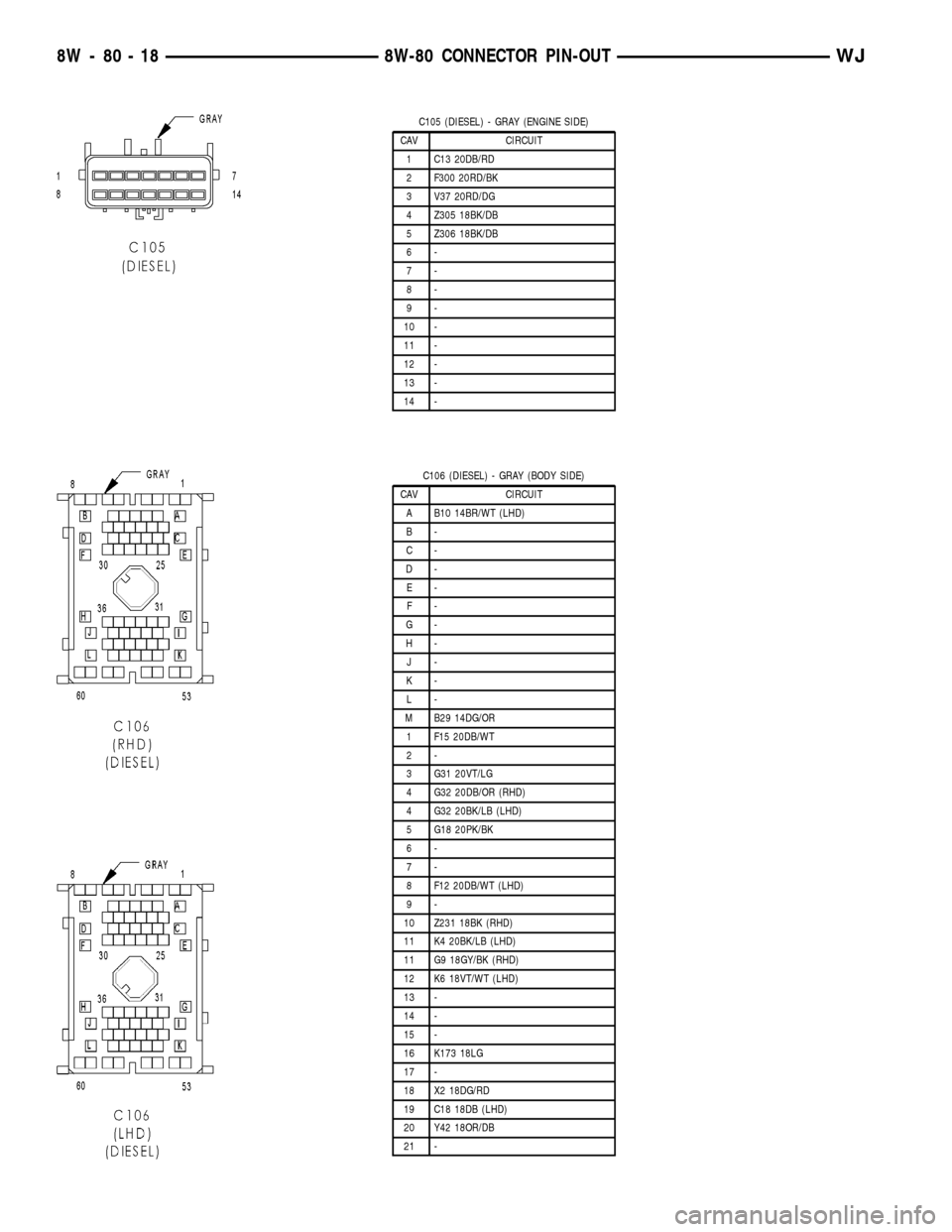
C105 (DIESEL) - GRAY (ENGINE SIDE)
CAV CIRCUIT
1 C13 20DB/RD
2 F300 20RD/BK
3 V37 20RD/DG
4 Z305 18BK/DB
5 Z306 18BK/DB
6-
7-
8-
9-
10 -
11 -
12 -
13 -
14 -
C106 (DIESEL) - GRAY (BODY SIDE)
CAV CIRCUIT
A B10 14BR/WT (LHD)
B-
C-
D-
E-
F-
G-
H-
J-
K-
L-
M B29 14DG/OR
1 F15 20DB/WT
2-
3 G31 20VT/LG
4 G32 20DB/OR (RHD)
4 G32 20BK/LB (LHD)
5 G18 20PK/BK
6-
7-
8 F12 20DB/WT (LHD)
9-
10 Z231 18BK (RHD)
11 K4 20BK/LB (LHD)
11 G9 18GY/BK (RHD)
12 K6 18VT/WT (LHD)
13 -
14 -
15 -
16 K173 18LG
17 -
18 X2 18DG/RD
19 C18 18DB (LHD)
20 Y42 18OR/DB
21 -
8W - 80 - 18 8W-80 CONNECTOR PIN-OUTWJ
Page 1082 of 2199
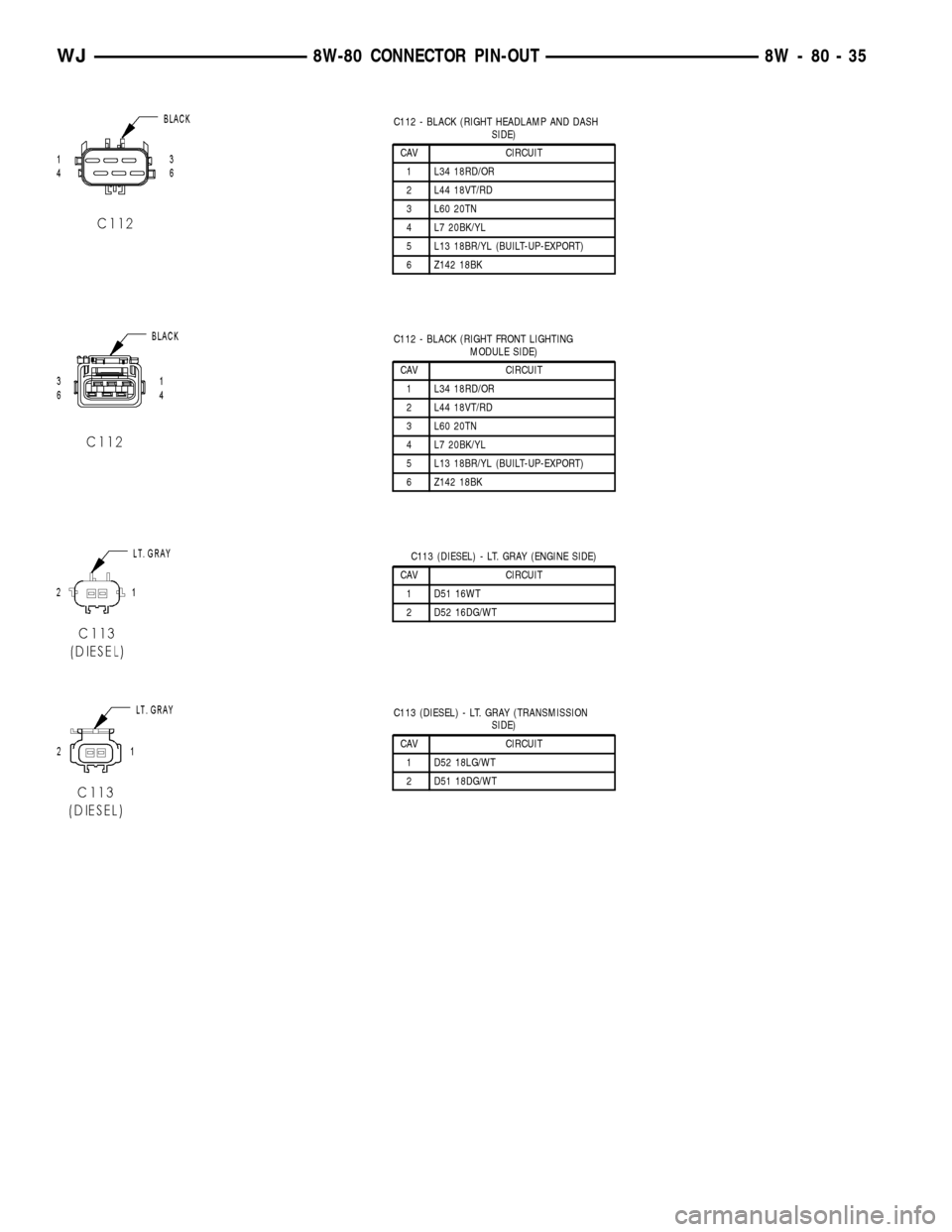
C112 - BLACK (RIGHT HEADLAMP AND DASH
SIDE)
CAV CIRCUIT
1 L34 18RD/OR
2 L44 18VT/RD
3 L60 20TN
4 L7 20BK/YL
5 L13 18BR/YL (BUILT-UP-EXPORT)
6 Z142 18BK
C112 - BLACK (RIGHT FRONT LIGHTING
MODULE SIDE)
CAV CIRCUIT
1 L34 18RD/OR
2 L44 18VT/RD
3 L60 20TN
4 L7 20BK/YL
5 L13 18BR/YL (BUILT-UP-EXPORT)
6 Z142 18BK
C113 (DIESEL) - LT. GRAY (ENGINE SIDE)
CAV CIRCUIT
1 D51 16WT
2 D52 16DG/WT
C113 (DIESEL) - LT. GRAY (TRANSMISSION
SIDE)
CAV CIRCUIT
1 D52 18LG/WT
2 D51 18DG/WT
WJ8W-80 CONNECTOR PIN-OUT 8W - 80 - 35
Page 1122 of 2199
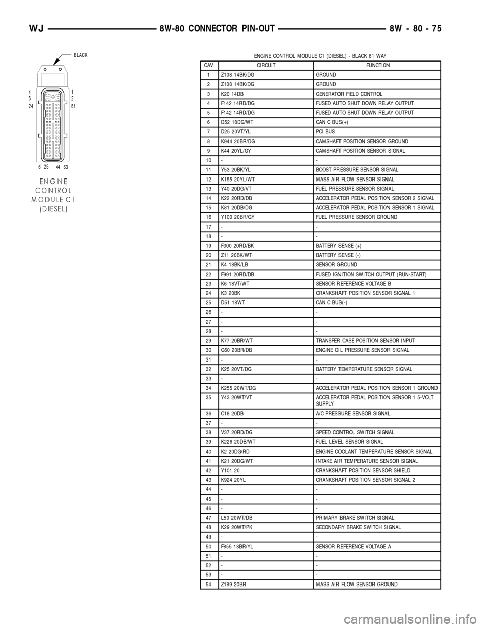
ENGINE CONTROL MODULE C1 (DIESEL) - BLACK 81 WAY
CAV CIRCUIT FUNCTION
1 Z108 14BK/DG GROUND
2 Z108 14BK/DG GROUND
3 K20 14DB GENERATOR FIELD CONTROL
4 F142 14RD/DG FUSED AUTO SHUT DOWN RELAY OUTPUT
5 F142 14RD/DG FUSED AUTO SHUT DOWN RELAY OUTPUT
6 D52 18DG/WT CAN C BUS(+)
7 D25 20VT/YL PCI BUS
8 K944 20BR/DG CAMSHAFT POSITION SENSOR GROUND
9 K44 20YL/GY CAMSHAFT POSITION SENSOR SIGNAL
10 - -
11 Y53 20BK/YL BOOST PRESSURE SENSOR SIGNAL
12 K155 20YL/WT MASS AIR FLOW SENSOR SIGNAL
13 Y40 20DG/VT FUEL PRESSURE SENSOR SIGNAL
14 K22 20RD/DB ACCELERATOR PEDAL POSITION SENSOR 2 SIGNAL
15 K81 20DB/DG ACCELERATOR PEDAL POSITION SENSOR 1 SIGNAL
16 Y100 20BR/GY FUEL PRESSURE SENSOR GROUND
17 - -
18 - -
19 F300 20RD/BK BATTERY SENSE (+)
20 Z11 20BK/WT BATTERY SENSE (-)
21 K4 18BK/LB SENSOR GROUND
22 F991 20RD/DB FUSED IGNITION SWITCH OUTPUT (RUN-START)
23 K6 18VT/WT SENSOR REFERENCE VOLTAGE B
24 K3 20BK CRANKSHAFT POSITION SENSOR SIGNAL 1
25 D51 18WT CAN C BUS(-)
26 - -
27 - -
28 - -
29 K77 20BR/WT TRANSFER CASE POSITION SENSOR INPUT
30 G60 20BR/DB ENGINE OIL PRESSURE SENSOR SIGNAL
31 - -
32 K25 20VT/DG BATTERY TEMPERATURE SENSOR SIGNAL
33 - -
34 K255 20WT/DG ACCELERATOR PEDAL POSITION SENSOR 1 GROUND
35 Y43 20WT/VT ACCELERATOR PEDAL POSITION SENSOR 1 5-VOLT
SUPPLY
36 C18 20DB A/C PRESSURE SENSOR SIGNAL
37 - -
38 V37 20RD/DG SPEED CONTROL SWITCH SIGNAL
39 K226 20DB/WT FUEL LEVEL SENSOR SIGNAL
40 K2 20DG/RD ENGINE COOLANT TEMPERATURE SENSOR SIGNAL
41 K21 20DG/WT INTAKE AIR TEMPERATURE SENSOR SIGNAL
42 Y101 20 CRANKSHAFT POSITION SENSOR SHIELD
43 K924 20YL CRANKSHAFT POSITION SENSOR SIGNAL 2
44 - -
45 - -
46 - -
47 L50 20WT/DB PRIMARY BRAKE SWITCH SIGNAL
48 K29 20WT/PK SECONDARY BRAKE SWITCH SIGNAL
49 - -
50 F855 18BR/YL SENSOR REFERENCE VOLTAGE A
51 - -
52 - -
53 - -
54 Z189 20BR MASS AIR FLOW SENSOR GROUND
WJ8W-80 CONNECTOR PIN-OUT 8W - 80 - 75