dimensions JEEP GRAND CHEROKEE 2003 WJ / 2.G User Guide
[x] Cancel search | Manufacturer: JEEP, Model Year: 2003, Model line: GRAND CHEROKEE, Model: JEEP GRAND CHEROKEE 2003 WJ / 2.GPages: 2199, PDF Size: 76.01 MB
Page 1415 of 2199

INSTALLATION
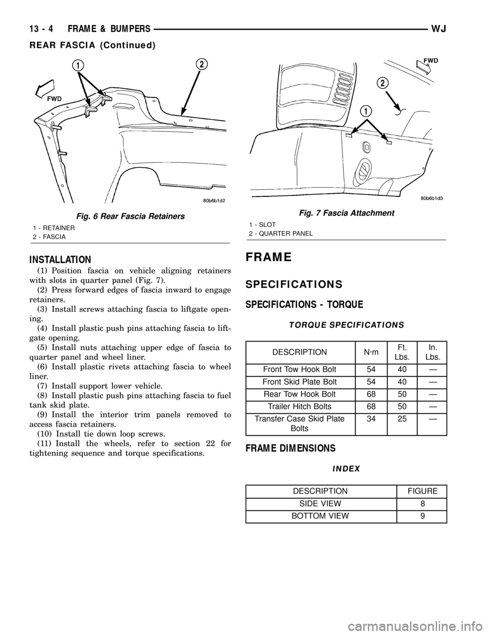
(1) Position fascia on vehicle aligning retainers
with slots in quarter panel (Fig. 7).
(2) Press forward edges of fascia inward to engage
retainers.
(3) Install screws attaching fascia to liftgate open-
ing.
(4) Install plastic push pins attaching fascia to lift-
gate opening.
(5) Install nuts attaching upper edge of fascia to
quarter panel and wheel liner.
(6) Install plastic rivets attaching fascia to wheel
liner.
(7) Install support lower vehicle.
(8) Install plastic push pins attaching fascia to fuel
tank skid plate.
(9) Install the interior trim panels removed to
access fascia retainers.
(10) Install tie down loop screws.
(11) Install the wheels, refer to section 22 for
tightening sequence and torque specifications.
FRAME
SPECIFICATIONS
SPECIFICATIONS - TORQUE
TORQUE SPECIFICATIONS
DESCRIPTION N´mFt.
Lbs.In.
Lbs.
Front Tow Hook Bolt 54 40 Ð
Front Skid Plate Bolt 54 40 Ð
Rear Tow Hook Bolt 68 50 Ð
Trailer Hitch Bolts 68 50 Ð
Transfer Case Skid Plate
Bolts34 25 Ð
FRAME DIMENSIONS
INDEX
DESCRIPTION FIGURE
SIDE VIEW 8
BOTTOM VIEW 9
Fig. 6 Rear Fascia Retainers
1 - RETAINER
2 - FASCIA
Fig. 7 Fascia Attachment
1 - SLOT
2 - QUARTER PANEL
13 - 4 FRAME & BUMPERSWJ
REAR FASCIA (Continued)
Page 1574 of 2199

SPECIFICATIONS
TRANSMISSION
GENERAL
Component Metric Inch
Planetary end play 0.127-1.22
mm0.005-0.048
in.
Input shaft end play 0.56-2.31
mm0.022-0.091
in.
Clutch pack clearance/
Front.1.70-
3.40mm0.067-0.134
in.
Clutch pack clearance/
Rear.0.559-0.914
mm0.022-0.036
in.
Front clutch 4 discs
Rear clutch 4 discs
Overdrive clutch 3 discs
Component Metric Inch
Direct clutch 6 discs
42RE Band adjustment
from 72 in. lbs.
Front band Back off 3 turns
Rear band Back off 4 turns
Recommended fluid MoparTATF +4, type 9602
GEAR RATIOS
1ST GEAR 2.74:1
2ND GEAR 1.54:1
3RD GEAR 1.0:1
4TH GEAR 0.69:1
REVERSE 2.21:1
THRUST WASHER/SPACER/SNAP-RING DIMENSIONS
Component Metric Inch
Front clutch thrust washer (reaction shaft
support hub)1.55 mm 0.061 in.
Rear clutch thrust washer (clutch retainer) 1.55 mm 0.061 in.
Intermediate shaft thrust plate (shaft hub pilot) Select fit to set end play
Output shaft thrust washer (rear clutch hub) 1.5-1.6 mm 0.060-0.063 in.
Rear clutch pack snap-ring 1.5 mm 0.060 in.
1.95 mm 0.076 in.
2.45 mm 0.098 in.
Planetary geartrain snap-ring (at front of output shaft) Select fit (three thicknesses avalible)
Overdrive piston thrust plate Thrust plate and
spacer are select fit.
Refer to size charts
and selection
procedures in
Overdrive Unit D&A
procedures Intermiediate shaft spacer
WJAUTOMATIC TRANSMISSION - 42RE 21 - 55
AUTOMATIC TRANSMISSION - 42RE (Continued)
Page 1984 of 2199

BODY STRUCTURE
TABLE OF CONTENTS
page page
GAP AND FLUSH
SPECIFICATIONS - GAP AND FLUSH.......112
OPENING DIMENSIONS
SPECIFICATIONS - BODY OPENING
DIMENSIONS........................114
SEALER LOCATIONS
SPECIFICATIONS
SEALER LOCATIONS.................118STUCTURAL ADHESIVE LOCATIONS
SPECIFICATIONS - STRUCTURAL ADHESIVE
LOCATIONS.........................137
WELD LOCATIONS
SPECIFICATIONS
WELD LOCATIONS...................153
GAP AND FLUSH
SPECIFICATIONS - GAP AND FLUSH
DESCIPTION FIGURE
FRONT VIEW 1
REAR VIEW 2
23 - 112 BODY STRUCTUREWJ
Page 1987 of 2199

OPENING DIMENSIONS
SPECIFICATIONS - BODY OPENING
DIMENSIONS
DESCRIPTION FIGURE
WINDSHIELD AND
FRONT DOOR
OPENING3
REAR DOOR AND
QUARTER GLASS
OPENING4
LIFTGATE OPENING
AND ENGINE
COMPARTMENT5
23 - 114 BODY STRUCTUREWJ
Page 1988 of 2199

Fig. 3 WINDSHIELD AND FRONT DOOR OPENING
WJBODY STRUCTURE 23 - 115
OPENING DIMENSIONS (Continued)
2002 WJ Service Manual
Publication No. 81-370-02064
TSB 26-11-01 November 2001
Page 1989 of 2199

Fig. 4 REAR DOOR AND QUARTER GLASS OPENING
23 - 116 BODY STRUCTUREWJ
OPENING DIMENSIONS (Continued)
Page 1990 of 2199

Fig. 5 LIFTGATE OPENING AND ENGINE COMPARTMENT
WJBODY STRUCTURE 23 - 117
OPENING DIMENSIONS (Continued)
Page 2093 of 2199

gap should be between 0.35 to 0.65 millimeter (0.014
to 0.026 inch). If the proper air gap is not obtained,
add or subtract shims as needed until the desired air
gap is obtained.
(9) Install the compressor shaft bolt. Tighten the
bolt to 13 N´m (115 in. lbs.).
NOTE: The shims may compress after tightening
the shaft bolt. Check the air gap in four or more
places to verify the air gap is still correct. Spin the
pulley before performing a final check of the air
gap.
(10) To complete the installation, (Refer to 24 -
HEATING & AIR CONDITIONING/PLUMBING/A/C
COMPRESSOR - INSTALLATION)
A/C COMPRESSOR CLUTCH
RELAY
DESCRIPTION
The compressor clutch relay is a International
Standards Organization (ISO) micro-relay. The termi-
nal designations and functions are the same as a con-
ventional ISO relay. However, the micro-relay
terminal orientation (footprint) is different, the cur-
rent capacity is lower, and the relay case dimensions
are smaller than those of the conventional ISO relay.
OPERATION
The compressor clutch relay is a electromechanical
device that switches battery current to the compres-
sor clutch coil when the Powertrain Control Module
(PCM) grounds the coil side of the relay. The PCM
responds to inputs from the a/c compressor switch on
the a/c heater control panel, the Automatic Zone Con-
trol (AZC) control module (if the vehicle is so
equipped), the a/c fin probe, and the a/c high pres-
sure transducer. (Refer to 24 - HEATING & AIR
CONDITIONING/CONTROLS/A/C COMPRESSOR
CLUTCH RELAY - DIAGNOSIS AND TESTING)
The compressor clutch relay is located in the Power
Distribution Center (PDC) in the engine compart-
ment. Refer to the PDC label for relay identification
and location.
The compressor clutch relay cannot be repaired
and, if faulty or damaged, it must be replaced.
DIAGNOSIS AND TESTING - A/C COMPRESSOR
CLUTCH RELAY
For circuit descriptions and diagrams, refer to the
appropriate wiring information.
The compressor clutch relay (Fig. 10) is located in
the Power Distribution Center (PDC). Refer to the
PDC label for relay identification and location.Remove the relay from the PDC to perform the fol-
lowing tests:
(1) A relay in the de-energized position should
have continuity between terminals 87A and 30, and
no continuity between terminals 87 and 30. If OK, go
to Step 2. If not OK, replace the faulty relay.
(2) Resistance between terminals 85 and 86 (elec-
tromagnet) should be 75 5 ohms. If OK, go to Step
3. If not OK, replace the faulty relay.
(3) Connect a battery to terminals 85 and 86.
There should now be continuity between terminals
30 and 87, and no continuity between terminals 87A
and 30. If OK, see the Relay Circuit Test procedure
in this group. If not OK, replace the faulty relay.
RELAY CIRCUIT TEST
For circuit descriptions and diagrams, refer to the
appropriate wiring information..
(1) The relay common feed terminal cavity (30) is
connected to fused battery feed. There should be bat-
tery voltage at the cavity for relay terminal 30 at all
times. If OK, go to Step 2. If not OK, repair the open
circuit to the fuse in the PDC as required.
(2) The relay normally closed terminal (87A) is not
used in this application. Go to Step 3.
(3) The relay normally open terminal cavity (87) is
connected to the compressor clutch coil. There should
be continuity between this cavity and the A/C com-
pressor clutch relay output circuit cavity of the com-
pressor clutch coil wire harness connector. If OK, go
to Step 4. If not OK, repair the open circuit as
required.
(4) The relay coil battery terminal (86) is con-
nected to the fused ignition switch output (run/start)
circuit. There should be battery voltage at the cavity
for relay terminal 86 with the ignition switch in the
On position. If OK, go to Step 5. If not OK, repair the
Fig. 10 A/C COMPRESSOR CLUTCH RELAY
30 - COMMON FEED
85 - COIL GROUND
86 - COIL BATTERY
87 - NORMALLY OPEN
87A - NORMALLY CLOSED
24 - 16 CONTROLSWJ
A/C COMPRESSOR CLUTCH (Continued)