shifter assembly JEEP GRAND CHEROKEE 2003 WJ / 2.G User Guide
[x] Cancel search | Manufacturer: JEEP, Model Year: 2003, Model line: GRAND CHEROKEE, Model: JEEP GRAND CHEROKEE 2003 WJ / 2.GPages: 2199, PDF Size: 76.01 MB
Page 1052 of 2199
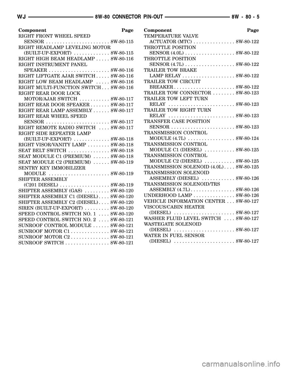
Component Page
RIGHT FRONT WHEEL SPEED
SENSOR....................... 8W-80-115
RIGHT HEADLAMP LEVELING MOTOR
(BUILT-UP-EXPORT)............. 8W-80-115
RIGHT HIGH BEAM HEADLAMP..... 8W-80-116
RIGHT INSTRUMENT PANEL
SPEAKER...................... 8W-80-116
RIGHT LIFTGATE AJAR SWITCH..... 8W-80-116
RIGHT LOW BEAM HEADLAMP..... 8W-80-116
RIGHT MULTI-FUNCTION SWITCH . . . 8W-80-116
RIGHT REAR DOOR LOCK
MOTOR/AJAR SWITCH........... 8W-80-117
RIGHT REAR DOOR SPEAKER....... 8W-80-117
RIGHT REAR LAMP ASSEMBLY...... 8W-80-117
RIGHT REAR WHEEL SPEED
SENSOR....................... 8W-80-117
RIGHT REMOTE RADIO SWITCH.... 8W-80-117
RIGHT SIDE REPEATER LAMP
(BUILT-UP-EXPORT)............. 8W-80-118
RIGHT VISOR/VANITY LAMP........ 8W-80-118
SEAT BELT SWITCH............... 8W-80-118
SEAT MODULE C1 (PREMIUM)...... 8W-80-118
SEAT MODULE C2 (PREMIUM)...... 8W-80-119
SENTRY KEY IMMOBILIZER
MODULE...................... 8W-80-119
SHIFTER ASSEMBLY
(C201 DIESEL).................. 8W-80-119
SHIFTER ASSEMBLY (GAS)......... 8W-80-120
SHIFTER ASSEMBLY C1 (DIESEL).... 8W-80-120
SHIFTER ASSEMBLY C2 (DIESEL).... 8W-80-120
SIREN (BUILT-UP-EXPORT)......... 8W-80-120
SPEED CONTROL SWITCH NO. 1.... 8W-80-120
SPEED CONTROL SWITCH NO. 2.... 8W-80-121
SUNROOF CONTROL MODULE...... 8W-80-121
SUNROOF MOTOR C1.............. 8W-80-121
SUNROOF MOTOR C2.............. 8W-80-121
SUNROOF SWITCH................ 8W-80-121Component Page
TEMPERATURE VALVE
ACTUATOR (MTC)............... 8W-80-122
THROTTLE POSITION
SENSOR (4.0L).................. 8W-80-122
THROTTLE POSITION
SENSOR (4.7L).................. 8W-80-122
TRAILER TOW BRAKE
LAMP RELAY................... 8W-80-122
TRAILER TOW CIRCUIT
BREAKER...................... 8W-80-122
TRAILER TOW CONNECTOR........ 8W-80-123
TRAILER TOW LEFT TURN
RELAY........................ 8W-80-123
TRAILER TOW RIGHT TURN
RELAY........................ 8W-80-123
TRANSFER CASE POSITION
SENSOR....................... 8W-80-123
TRANSMISSION CONTROL
MODULE (4.7L)................. 8W-80-124
TRANSMISSION CONTROL
MODULE C1 (DIESEL)........... 8W-80-125
TRANSMISSION CONTROL
MODULE C2 (DIESEL)........... 8W-80-125
TRANSMISSION SOLENOID (4.0L).... 8W-80-125
TRANSMISSION SOLENOID
ASSEMBLY (DIESEL)............ 8W-80-126
TRANSMISSION SOLENOID/TRS
ASSEMBLY (4.7L)................ 8W-80-126
UNDERHOOD LAMP............... 8W-80-126
VEHICLE INFORMATION CENTER . . . 8W-80-127
VISCOUS/CABIN HEATER
(DIESEL)...................... 8W-80-127
WASHER FLUID LEVEL SWITCH.... 8W-80-127
WASTEGATE SOLENOID
(DIESEL)...................... 8W-80-127
WATER IN FUEL SENSOR
(DIESEL)...................... 8W-80-127
WJ8W-80 CONNECTOR PIN-OUT 8W - 80 - 5
Page 1086 of 2199

C200 - GRAY/LHD BLACK/RHD (INSTRUMENT
PANEL SIDE)
CAV CIRCUIT
41 X58 18DB/OR
42 -
43 V13 18BR/LG
44 V14 20RD/VT
45 -
46 V20 18BK/WT
47 V22 18BR/YL
48 R46 20BR/LB
49 X64 18BR/WT
50 Z305 20BK/OR
51 Z306 20BK/LG
52 R48 20TN
53 G32 20BK/LB
54 G31 20VT/LG
55 Z9 16BK
56 V11 20BK/TN
57 G18 20PK/BK
58 V37 20RD/LG
59 K4 20BK/LB
60 -
C201 (DIESEL) - WHITE (INSTRUMENT PANEL
SIDE)
CAV CIRCUIT
1-
2 Z300 18BK
3 E2 20OR
4 K29 18WT/PK
5 D25 20YL/VT
6 D19 20VT/OR
7 D21 20PK
8 F12 20DB/WT
9 T2 20TN/BK
10 Z234 18BK
11 T41 18BK/WT
12 F991 18OR/DB
C201 (DIESEL) - WHITE (SHIFTER ASSEMBLY SIDE)
CAV CIRCUIT
1-
2-
3-
4 K2 20WT/PK
5 D25 20RD
6-
7 D21 20PK
8 F12 20DB/WT
9 T2 20TN/BK
10 Z234 20WT
11 T41 20BK/WT
12 F991 20OR/DB
WJ8W-80 CONNECTOR PIN-OUT 8W - 80 - 39
Page 1113 of 2199
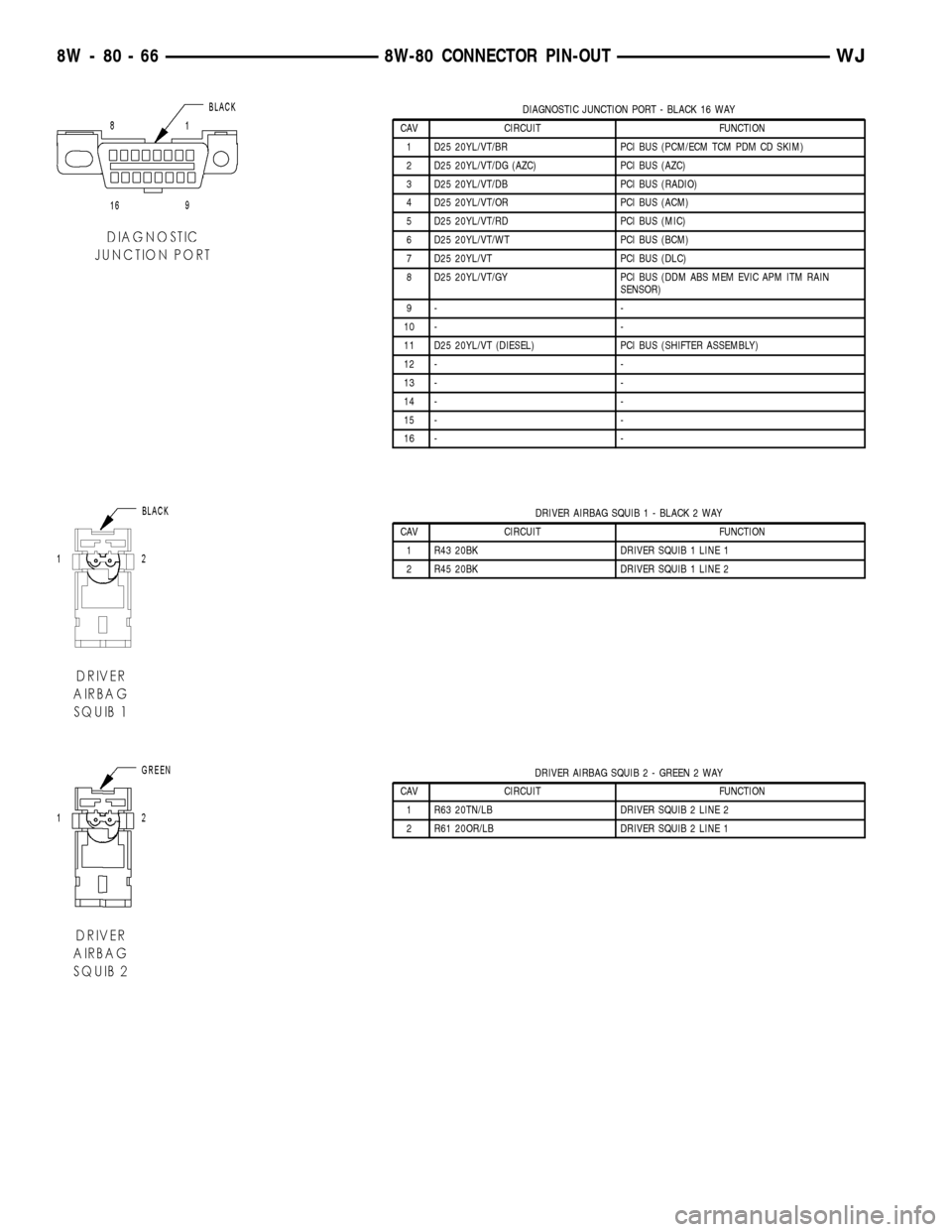
DIAGNOSTIC JUNCTION PORT - BLACK 16 WAY
CAV CIRCUIT FUNCTION
1 D25 20YL/VT/BR PCI BUS (PCM/ECM TCM PDM CD SKIM)
2 D25 20YL/VT/DG (AZC) PCI BUS (AZC)
3 D25 20YL/VT/DB PCI BUS (RADIO)
4 D25 20YL/VT/OR PCI BUS (ACM)
5 D25 20YL/VT/RD PCI BUS (MIC)
6 D25 20YL/VT/WT PCI BUS (BCM)
7 D25 20YL/VT PCI BUS (DLC)
8 D25 20YL/VT/GY PCI BUS (DDM ABS MEM EVIC APM ITM RAIN
SENSOR)
9- -
10 - -
11 D25 20YL/VT (DIESEL) PCI BUS (SHIFTER ASSEMBLY)
12 - -
13 - -
14 - -
15 - -
16 - -
DRIVER AIRBAG SQUIB 1 - BLACK 2 WAY
CAV CIRCUIT FUNCTION
1 R43 20BK DRIVER SQUIB 1 LINE 1
2 R45 20BK DRIVER SQUIB 1 LINE 2
DRIVER AIRBAG SQUIB 2 - GREEN 2 WAY
CAV CIRCUIT FUNCTION
1 R63 20TN/LB DRIVER SQUIB 2 LINE 2
2 R61 20OR/LB DRIVER SQUIB 2 LINE 1
8W - 80 - 66 8W-80 CONNECTOR PIN-OUTWJ
Page 1166 of 2199
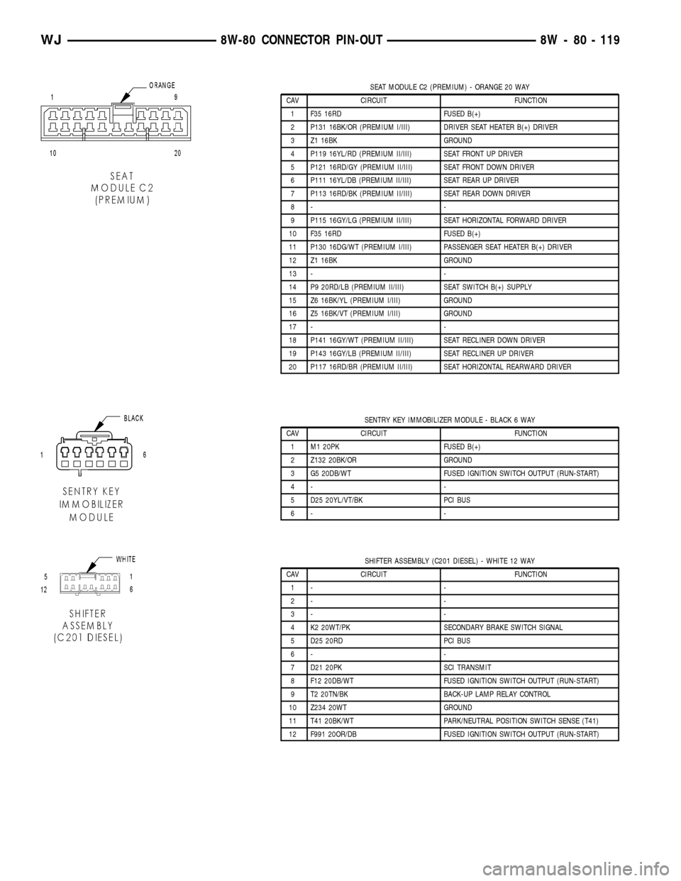
SEAT MODULE C2 (PREMIUM) - ORANGE 20 WAY
CAV CIRCUIT FUNCTION
1 F35 16RD FUSED B(+)
2 P131 16BK/OR (PREMIUM I/III) DRIVER SEAT HEATER B(+) DRIVER
3 Z1 16BK GROUND
4 P119 16YL/RD (PREMIUM II/III) SEAT FRONT UP DRIVER
5 P121 16RD/GY (PREMIUM II/III) SEAT FRONT DOWN DRIVER
6 P111 16YL/DB (PREMIUM II/III) SEAT REAR UP DRIVER
7 P113 16RD/BK (PREMIUM II/III) SEAT REAR DOWN DRIVER
8- -
9 P115 16GY/LG (PREMIUM II/III) SEAT HORIZONTAL FORWARD DRIVER
10 F35 16RD FUSED B(+)
11 P130 16DG/WT (PREMIUM I/III) PASSENGER SEAT HEATER B(+) DRIVER
12 Z1 16BK GROUND
13 - -
14 P9 20RD/LB (PREMIUM II/III) SEAT SWITCH B(+) SUPPLY
15 Z6 16BK/YL (PREMIUM I/III) GROUND
16 Z5 16BK/VT (PREMIUM I/III) GROUND
17 - -
18 P141 16GY/WT (PREMIUM II/III) SEAT RECLINER DOWN DRIVER
19 P143 16GY/LB (PREMIUM II/III) SEAT RECLINER UP DRIVER
20 P117 16RD/BR (PREMIUM II/III) SEAT HORIZONTAL REARWARD DRIVER
SENTRY KEY IMMOBILIZER MODULE - BLACK 6 WAY
CAV CIRCUIT FUNCTION
1 M1 20PK FUSED B(+)
2 Z132 20BK/OR GROUND
3 G5 20DB/WT FUSED IGNITION SWITCH OUTPUT (RUN-START)
4- -
5 D25 20YL/VT/BK PCI BUS
6- -
SHIFTER ASSEMBLY (C201 DIESEL) - WHITE 12 WAY
CAV CIRCUIT FUNCTION
1- -
2- -
3- -
4 K2 20WT/PK SECONDARY BRAKE SWITCH SIGNAL
5 D25 20RD PCI BUS
6- -
7 D21 20PK SCI TRANSMIT
8 F12 20DB/WT FUSED IGNITION SWITCH OUTPUT (RUN-START)
9 T2 20TN/BK BACK-UP LAMP RELAY CONTROL
10 Z234 20WT GROUND
11 T41 20BK/WT PARK/NEUTRAL POSITION SWITCH SENSE (T41)
12 F991 20OR/DB FUSED IGNITION SWITCH OUTPUT (RUN-START)
WJ8W-80 CONNECTOR PIN-OUT 8W - 80 - 119
Page 1167 of 2199
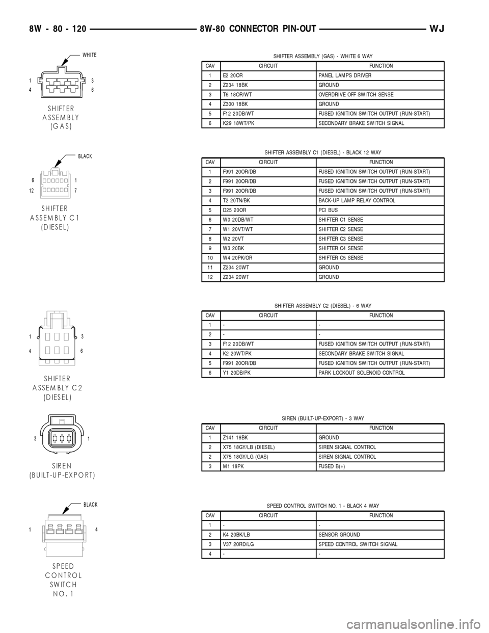
SHIFTER ASSEMBLY (GAS) - WHITE 6 WAY
CAV CIRCUIT FUNCTION
1 E2 20OR PANEL LAMPS DRIVER
2 Z234 18BK GROUND
3 T6 18OR/WT OVERDRIVE OFF SWITCH SENSE
4 Z300 18BK GROUND
5 F12 20DB/WT FUSED IGNITION SWITCH OUTPUT (RUN-START)
6 K29 18WT/PK SECONDARY BRAKE SWITCH SIGNAL
SHIFTER ASSEMBLY C1 (DIESEL) - BLACK 12 WAY
CAV CIRCUIT FUNCTION
1 F991 20OR/DB FUSED IGNITION SWITCH OUTPUT (RUN-START)
2 F991 20OR/DB FUSED IGNITION SWITCH OUTPUT (RUN-START)
3 F991 20OR/DB FUSED IGNITION SWITCH OUTPUT (RUN-START)
4 T2 20TN/BK BACK-UP LAMP RELAY CONTROL
5 D25 20OR PCI BUS
6 W0 20DB/WT SHIFTER C1 SENSE
7 W1 20VT/WT SHIFTER C2 SENSE
8 W2 20VT SHIFTER C3 SENSE
9 W3 20BK SHIFTER C4 SENSE
10 W4 20PK/OR SHIFTER C5 SENSE
11 Z234 20WT GROUND
12 Z234 20WT GROUND
SHIFTER ASSEMBLY C2 (DIESEL)-6WAY
CAV CIRCUIT FUNCTION
1- -
2- -
3 F12 20DB/WT FUSED IGNITION SWITCH OUTPUT (RUN-START)
4 K2 20WT/PK SECONDARY BRAKE SWITCH SIGNAL
5 F991 20OR/DB FUSED IGNITION SWITCH OUTPUT (RUN-START)
6 Y1 20DB/PK PARK LOCKOUT SOLENOID CONTROL
SIREN (BUILT-UP-EXPORT)-3WAY
CAV CIRCUIT FUNCTION
1 Z141 18BK GROUND
2 X75 18GY/LB (DIESEL) SIREN SIGNAL CONTROL
2 X75 18GY/LG (GAS) SIREN SIGNAL CONTROL
3 M1 18PK FUSED B(+)
SPEED CONTROL SWITCH NO. 1 - BLACK 4 WAY
CAV CIRCUIT FUNCTION
1- -
2 K4 20BK/LB SENSOR GROUND
3 V37 20RD/LG SPEED CONTROL SWITCH SIGNAL
4- -
8W - 80 - 120 8W-80 CONNECTOR PIN-OUTWJ
Page 1185 of 2199
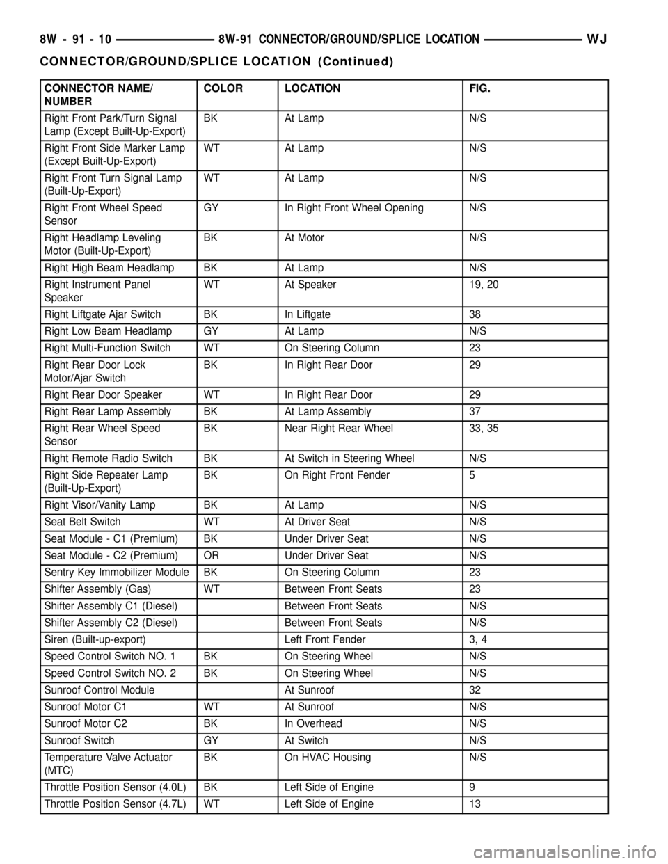
CONNECTOR NAME/
NUMBERCOLOR LOCATION FIG.
Right Front Park/Turn Signal
Lamp (Except Built-Up-Export)BK At Lamp N/S
Right Front Side Marker Lamp
(Except Built-Up-Export)WT At Lamp N/S
Right Front Turn Signal Lamp
(Built-Up-Export)WT At Lamp N/S
Right Front Wheel Speed
SensorGY In Right Front Wheel Opening N/S
Right Headlamp Leveling
Motor (Built-Up-Export)BK At Motor N/S
Right High Beam Headlamp BK At Lamp N/S
Right Instrument Panel
SpeakerWT At Speaker 19, 20
Right Liftgate Ajar Switch BK In Liftgate 38
Right Low Beam Headlamp GY At Lamp N/S
Right Multi-Function Switch WT On Steering Column 23
Right Rear Door Lock
Motor/Ajar SwitchBK In Right Rear Door 29
Right Rear Door Speaker WT In Right Rear Door 29
Right Rear Lamp Assembly BK At Lamp Assembly 37
Right Rear Wheel Speed
SensorBK Near Right Rear Wheel 33, 35
Right Remote Radio Switch BK At Switch in Steering Wheel N/S
Right Side Repeater Lamp
(Built-Up-Export)BK On Right Front Fender 5
Right Visor/Vanity Lamp BK At Lamp N/S
Seat Belt Switch WT At Driver Seat N/S
Seat Module - C1 (Premium) BK Under Driver Seat N/S
Seat Module - C2 (Premium) OR Under Driver Seat N/S
Sentry Key Immobilizer Module BK On Steering Column 23
Shifter Assembly (Gas) WT Between Front Seats 23
Shifter Assembly C1 (Diesel) Between Front Seats N/S
Shifter Assembly C2 (Diesel) Between Front Seats N/S
Siren (Built-up-export) Left Front Fender 3, 4
Speed Control Switch NO. 1 BK On Steering Wheel N/S
Speed Control Switch NO. 2 BK On Steering Wheel N/S
Sunroof Control Module At Sunroof 32
Sunroof Motor C1 WT At Sunroof N/S
Sunroof Motor C2 BK In Overhead N/S
Sunroof Switch GY At Switch N/S
Temperature Valve Actuator
(MTC)BK On HVAC Housing N/S
Throttle Position Sensor (4.0L) BK Left Side of Engine 9
Throttle Position Sensor (4.7L) WT Left Side of Engine 13
8W - 91 - 10 8W-91 CONNECTOR/GROUND/SPLICE LOCATIONWJ
CONNECTOR/GROUND/SPLICE LOCATION (Continued)
Page 1487 of 2199
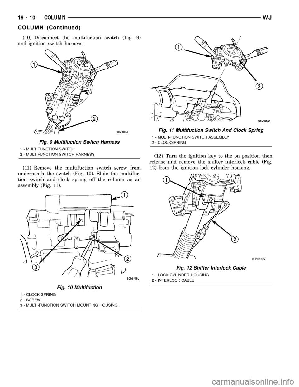
(10) Disconnect the multifuction switch (Fig. 9)
and ignition switch harness.
(11) Remove the multifuction switch screw from
underneath the switch (Fig. 10). Slide the multifuc-
tion switch and clock spring off the column as an
assembly (Fig. 11).(12) Turn the ignition key to the on position then
release and remove the shifter interlock cable (Fig.
12) from the ignition lock cylinder housing.
Fig. 9 Multifuction Switch Harness
1 - MULTIFUNCTION SWITCH
2 - MULTIFUNCTION SWITCH HARNESS
Fig. 10 Multifuction
1 - CLOCK SPRING
2 - SCREW
3 - MULTI-FUNCTION SWITCH MOUNTING HOUSING
Fig. 11 Multifuction Switch And Clock Spring
1 - MULTI-FUNCTION SWITCH ASSEMBLY
2 - CLOCKSPRING
Fig. 12 Shifter Interlock Cable
1 - LOCK CYLINDER HOUSING
2 - INTERLOCK CABLE
19 - 10 COLUMNWJ
COLUMN (Continued)
Page 1488 of 2199
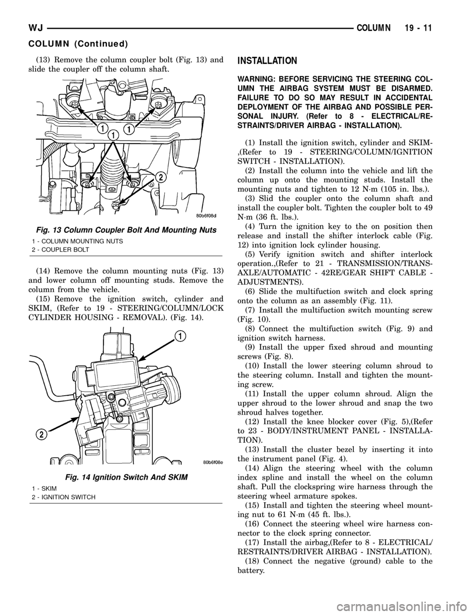
(13) Remove the column coupler bolt (Fig. 13) and
slide the coupler off the column shaft.
(14) Remove the column mounting nuts (Fig. 13)
and lower column off mounting studs. Remove the
column from the vehicle.
(15) Remove the ignition switch, cylinder and
SKIM, (Refer to 19 - STEERING/COLUMN/LOCK
CYLINDER HOUSING - REMOVAL). (Fig. 14).INSTALLATION
WARNING: BEFORE SERVICING THE STEERING COL-
UMN THE AIRBAG SYSTEM MUST BE DISARMED.
FAILURE TO DO SO MAY RESULT IN ACCIDENTAL
DEPLOYMENT OF THE AIRBAG AND POSSIBLE PER-
SONAL INJURY. (Refer to 8 - ELECTRICAL/RE-
STRAINTS/DRIVER AIRBAG - INSTALLATION).
(1) Install the ignition switch, cylinder and SKIM-
,(Refer to 19 - STEERING/COLUMN/IGNITION
SWITCH - INSTALLATION).
(2) Install the column into the vehicle and lift the
column up onto the mounting studs. Install the
mounting nuts and tighten to 12 N´m (105 in. lbs.).
(3) Slid the coupler onto the column shaft and
install the coupler bolt. Tighten the coupler bolt to 49
N´m (36 ft. lbs.).
(4) Turn the ignition key to the on position then
release and install the shifter interlock cable (Fig.
12) into ignition lock cylinder housing.
(5) Verify ignition switch and shifter interlock
operation.,(Refer to 21 - TRANSMISSION/TRANS-
AXLE/AUTOMATIC - 42RE/GEAR SHIFT CABLE -
ADJUSTMENTS).
(6) Slide the multifuction switch and clock spring
onto the column as an assembly (Fig. 11).
(7) Install the multifuction switch mounting screw
(Fig. 10).
(8) Connect the multifuction switch (Fig. 9) and
ignition switch harness.
(9) Install the upper fixed shroud and mounting
screws (Fig. 8).
(10) Install the lower steering column shroud to
the steering column. Install and tighten the mount-
ing screw.
(11) Install the upper column shroud. Align the
upper shroud to the lower shroud and snap the two
shroud halves together.
(12) Install the knee blocker cover (Fig. 5),(Refer
to 23 - BODY/INSTRUMENT PANEL - INSTALLA-
TION).
(13) Install the cluster bezel by inserting it into
the instrument panel (Fig. 4).
(14) Align the steering wheel with the column
index spline and install the wheel on the column
shaft. Pull the clockspring wire harness through the
steering wheel armature spokes.
(15) Install and tighten the steering wheel mount-
ing nut to 61 N´m (45 ft. lbs.).
(16) Connect the steering wheel wire harness con-
nector to the clock spring connector.
(17) Install the airbag,(Refer to 8 - ELECTRICAL/
RESTRAINTS/DRIVER AIRBAG - INSTALLATION).
(18) Connect the negative (ground) cable to the
battery.
Fig. 13 Column Coupler Bolt And Mounting Nuts
1 - COLUMN MOUNTING NUTS
2 - COUPLER BOLT
Fig. 14 Ignition Switch And SKIM
1 - SKIM
2 - IGNITION SWITCH
WJCOLUMN 19 - 11
COLUMN (Continued)
Page 1489 of 2199
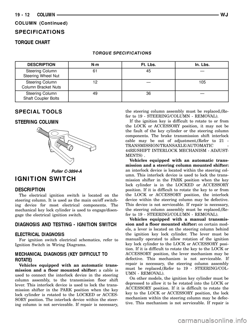
SPECIFICATIONS
TORQUE CHART
TORQUE SPECIFICATIONS
DESCRIPTION N´m Ft. Lbs. In. Lbs.
Steering Column
Steering Wheel Nut61 45 Ð
Steering Column
Column Bracket Nuts12 Ð 105
Steering Column
Shaft Coupler Bolts49 36 Ð
SPECIAL TOOLS
STEERING COLUMN
IGNITION SWITCH
DESCRIPTION
The electrical ignition switch is located on the
steering column. It is used as the main on/off switch-
ing device for most electrical components. The
mechanical key lock cylinder is used to engage/disen-
gage the electrical ignition switch.
DIAGNOSIS AND TESTING - IGNITION SWITCH
ELECTRICAL DIAGNOSIS
For ignition switch electrical schematics, refer to
Ignition Switch in Wiring Diagrams.
MECHANICAL DIAGNOSIS (KEY DIFFICULT TO
ROTATE)
Vehicles equipped with an automatic trans-
mission and a floor mounted shifter:a cable is
used to connect the interlock device in the steering
column assembly, to the transmission floor shift
lever. This interlock device is used to lock the trans-
mission shifter in the PARK position when the key
lock cylinder is rotated to the LOCKED or ACCES-
SORY position. The interlock device within the steer-
ing column is not serviceable. If repair is necessary,the steering column assembly must be replaced,(Re-
fer to 19 - STEERING/COLUMN - REMOVAL).
If the ignition key is difficult to rotate to or from
the LOCK or ACCESSORY position, it may not be
the fault of the key cylinder or the steering column
components. The brake transmission shift interlock
cable may be out of adjustment,(Refer to 21 -
TRANSMISSION/TRANSAXLE/AUTOMATIC -
44RE/SHIFT INTERLOCK MECHANISM - ADJUST-
MENTS) .
Vehicles equipped with an automatic trans-
mission and a steering column mounted shifter:
an interlock device is located within the steering col-
umn. This interlock device is used to lock the trans-
mission shifter in the PARK position when the key
lock cylinder is in the LOCKED or ACCESSORY
position. If it is difficult to rotate the key to or from
the LOCK or ACCESSORY position, the interlock
device within the steering column may be defective.
This device is not serviceable. If repair is necessary,
the steering column assembly must be replaced,(Re-
fer to 19 - STEERING/COLUMN - REMOVAL).
Vehicles equipped with a manual transmis-
sion and a floor mounted shifter:on certain mod-
els, a lever is located on the steering column behind
the ignition key lock cylinder. The lever must be
manually operated to allow rotation of the ignition
key lock cylinder to the LOCK or ACCESSORY posi-
tion. If it is difficult to rotate the key to the LOCK or
ACCESSORY position, the lever mechanism may be
defective. This mechanism is not serviceable. If
repair is necessary, the steering column assembly
must be replaced,(Refer to 19 - STEERING/COL-
UMN - REMOVAL).
On other models, the ignition key cylinder must be
depressed to allow it to be rotated into the LOCK or
ACCESSORY position. If it is difficult to rotate the
key to the LOCK or ACCESSORY position, the lock
mechanism within the steering column may be defec-
tive. This mechanism is not serviceable. If repair is
Puller C-3894-A
19 - 12 COLUMNWJ
COLUMN (Continued)
Page 1582 of 2199
BRAKE TRANSMISSION SHIFT
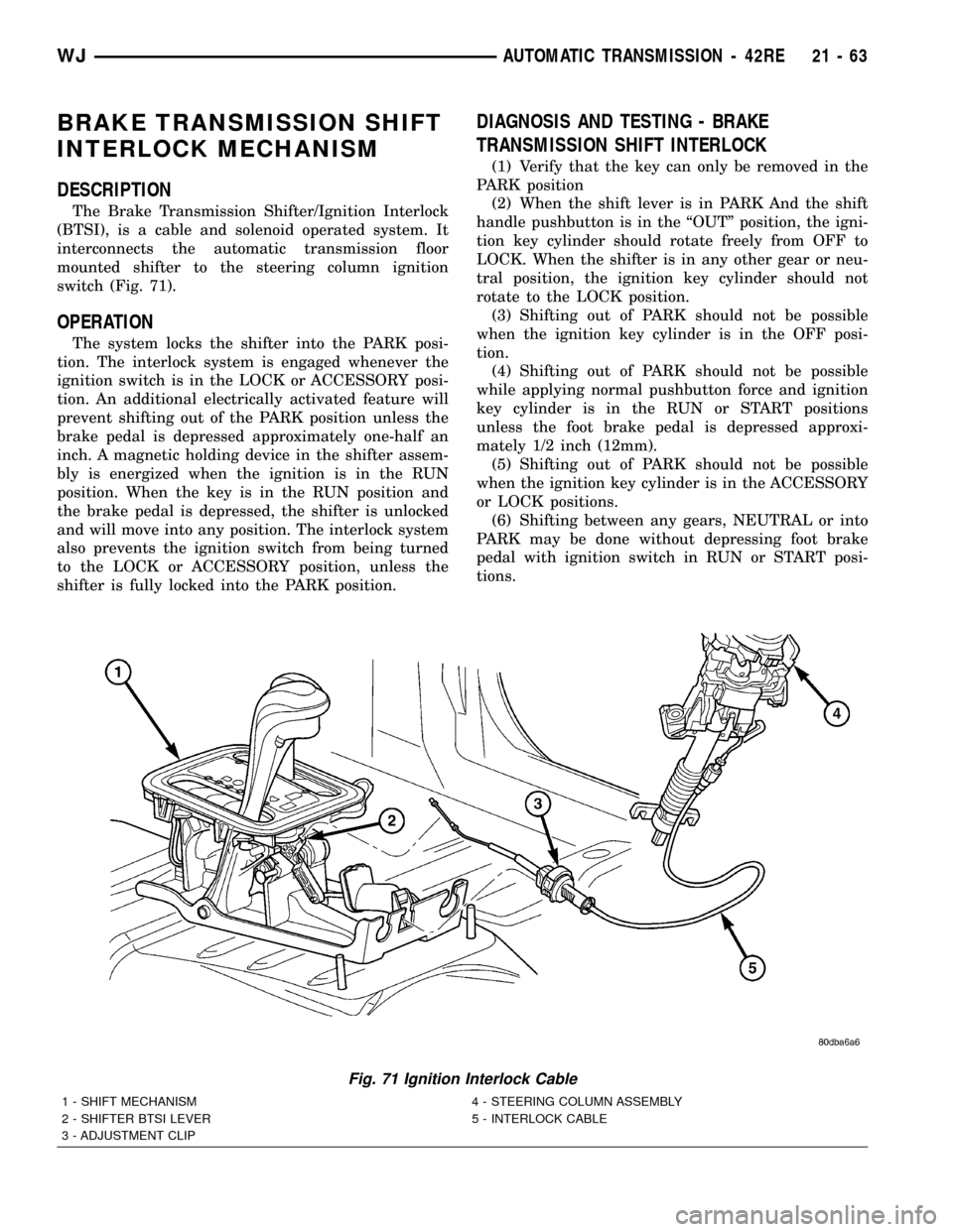
INTERLOCK MECHANISM
DESCRIPTION
The Brake Transmission Shifter/Ignition Interlock
(BTSI), is a cable and solenoid operated system. It
interconnects the automatic transmission floor
mounted shifter to the steering column ignition
switch (Fig. 71).
OPERATION
The system locks the shifter into the PARK posi-
tion. The interlock system is engaged whenever the
ignition switch is in the LOCK or ACCESSORY posi-
tion. An additional electrically activated feature will
prevent shifting out of the PARK position unless the
brake pedal is depressed approximately one-half an
inch. A magnetic holding device in the shifter assem-
bly is energized when the ignition is in the RUN
position. When the key is in the RUN position and
the brake pedal is depressed, the shifter is unlocked
and will move into any position. The interlock system
also prevents the ignition switch from being turned
to the LOCK or ACCESSORY position, unless the
shifter is fully locked into the PARK position.
DIAGNOSIS AND TESTING - BRAKE
TRANSMISSION SHIFT INTERLOCK
(1) Verify that the key can only be removed in the
PARK position
(2) When the shift lever is in PARK And the shift
handle pushbutton is in the ªOUTº position, the igni-
tion key cylinder should rotate freely from OFF to
LOCK. When the shifter is in any other gear or neu-
tral position, the ignition key cylinder should not
rotate to the LOCK position.
(3) Shifting out of PARK should not be possible
when the ignition key cylinder is in the OFF posi-
tion.
(4) Shifting out of PARK should not be possible
while applying normal pushbutton force and ignition
key cylinder is in the RUN or START positions
unless the foot brake pedal is depressed approxi-
mately 1/2 inch (12mm).
(5) Shifting out of PARK should not be possible
when the ignition key cylinder is in the ACCESSORY
or LOCK positions.
(6) Shifting between any gears, NEUTRAL or into
PARK may be done without depressing foot brake
pedal with ignition switch in RUN or START posi-
tions.
Fig. 71 Ignition Interlock Cable
1 - SHIFT MECHANISM 4 - STEERING COLUMN ASSEMBLY
2 - SHIFTER BTSI LEVER 5 - INTERLOCK CABLE
3 - ADJUSTMENT CLIP
WJAUTOMATIC TRANSMISSION - 42RE 21 - 63