transmission oil JEEP GRAND CHEROKEE 2003 WJ / 2.G User Guide
[x] Cancel search | Manufacturer: JEEP, Model Year: 2003, Model line: GRAND CHEROKEE, Model: JEEP GRAND CHEROKEE 2003 WJ / 2.GPages: 2199, PDF Size: 76.01 MB
Page 278 of 2199
TRANSMISSION
TABLE OF CONTENTS
page page
TRANS COOLER
DESCRIPTION.........................55STANDARD PROCEDURE - FLUSHING
COOLERS AND TUBES.................55
TRANS COOLER
DESCRIPTION
An internal high capacity/high efficiency cooler is
used on all vehicles these coolers are an oil-to-coolant
type which consists of plates mounted in the radiator
outlet tank (Fig. 36). Because the internal oil cooler
is so efficient, no auxiliary oil cooler is offered The
cooler is not servicable seperatly from the radiator.
STANDARD PROCEDURE - FLUSHING
COOLERS AND TUBES
When a transmission failure has contaminated the
fluid, the oil cooler(s) must be flushed. The torque
converter must also be replaced. This will insure that
metal particles or sludged oil are not later trans-
ferred back into the reconditioned (or replaced) trans-
mission.
The only recommended procedure for flushing cool-
ers and lines is to use Tool 6906-B Cooler Flusher.
WARNING: WEAR PROTECTIVE EYEWEAR THAT
MEETS THE REQUIREMENTS OF OSHA AND ANSI
Z87.1±1968. WEAR STANDARD INDUSTRIAL RUB-
BER GLOVES.
KEEP LIGHTED CIGARETTES, SPARKS, FLAMES,
AND OTHER IGNITION SOURCES AWAY FROM THE
AREA TO PREVENT THE IGNITION OF COMBUSTI-
BLE LIQUIDS AND GASES. KEEP A CLASS (B) FIRE
EXTINGUISHER IN THE AREA WHERE THE
FLUSHER WILL BE USED.
KEEP THE AREA WELL VENTILATED.
DO NOT LET FLUSHING SOLVENT COME IN CON-
TACT WITH YOUR EYES OR SKIN: IF EYE CONTAM-
INATION OCCURS, FLUSH EYES WITH WATER FOR
15 TO 20 SECONDS. REMOVE CONTAMINATED
CLOTHING AND WASH AFFECTED SKIN WITH
SOAP AND WATER. SEEK MEDICAL ATTENTION.
(1) Remove cover plate filler plug on Tool 6906-B.
Fill reservoir 1/2 to 3/4 full of fresh flushing solution.
Flushing solvents are petroleum based solutions gen-
erally used to clean automatic transmission compo-
nents.DO NOTuse solvents containing acids, water,
gasoline, or any other corrosive liquids.(2) Reinstall filler plug on Tool 6906-B.
(3) Verify pump power switch is turned OFF. Con-
nect red alligator clip to positive (+) battery post.
Connect black (-) alligator clip to a good ground.
(4) Disconnect the cooler lines at the transmission.
NOTE: When flushing transmission cooler and
lines, ALWAYS reverse flush.
NOTE: The converter drainback valve must be
removed and an appropriate replacement hose
installed to bridge the space between the transmis-
sion cooler line and the cooler fitting. Failure to
remove the drainback valve will prevent reverse
flushing the system. A suitable replacement hose
can be found in the adapter kit supplied with the
flushing tool.
(5) Connect the BLUE pressure line to the OUT-
LET (From) cooler line.
(6) Connect the CLEAR return line to the INLET
(To) cooler line
(7) Turn pump ON for two to three minutes to
flush cooler(s) and lines.
(8) Turn pump OFF.
(9) Disconnect CLEAR suction line from reservoir
at cover plate. Disconnect CLEAR return line at
cover plate, and place it in a drain pan.
(10) Turn pump ON for 30 seconds to purge flush-
ing solution from cooler and lines. Turn pump OFF.
(11) Place CLEAR suction line into a one quart
container of MopartATF +4, type 9602, Automatic
Transmission Fluid.
(12) Turn pump ON until all transmission fluid is
removed from the one quart container and lines. This
purges any residual cleaning solvent from the trans-
mission cooler and lines. Turn pump OFF.
(13) Disconnect alligator clips from battery. Recon-
nect flusher lines to cover plate, and remove flushing
adapters from cooler lines.
WJTRANSMISSION 7 - 55
Page 324 of 2199
DESCRIPTION - POWER GROUNDS
The Powertrain Control Module (PCM) has 2 main
grounds. Both of these grounds are referred to as
power grounds. All of the high-current, noisy, electri-
cal devices are connected to these grounds as well as
all of the sensor returns. The sensor return comes
into the sensor return circuit, passes through noise
suppression, and is then connected to the power
ground.
The power ground is used to control ground cir-
cuits for the following PCM loads:
²Generator field winding
²Fuel injectors
²Ignition coil(s)
²Certain relays/solenoids
²Certain sensors
DESCRIPTION - SENSOR RETURN
The Sensor Return circuits are internal to the Pow-
ertrain Control Module (PCM).
Sensor Return provides a low±noise ground refer-
ence for all engine control system sensors. Refer to
Power Grounds for more information.
OPERATION
OPERATION - PCM
(1) Also refer to Modes of Operation.
The PCM operates the fuel system. The PCM is a
pre-programmed, triple microprocessor digital com-
puter. It regulates ignition timing, air-fuel ratio,
emission control devices, charging system, certain
transmission features, speed control, air conditioning
compressor clutch engagement and idle speed. The
PCM can adapt its programming to meet changing
operating conditions.
The PCM receives input signals from various
switches and sensors. Based on these inputs, the
PCM regulates various engine and vehicle operations
through different system components. These compo-
nents are referred to as Powertrain Control Module
(PCM) Outputs. The sensors and switches that pro-
vide inputs to the PCM are considered Powertrain
Control Module (PCM) Inputs.
The PCM adjusts ignition timing based upon
inputs it receives from sensors that react to: engine
rpm, manifold absolute pressure, engine coolant tem-
perature, throttle position, transmission gear selec-
tion (automatic transmission), vehicle speed and the
brake switch.
The PCM adjusts idle speed based on inputs it
receives from sensors that react to: throttle position,
vehicle speed, transmission gear selection, engine
coolant temperature and from inputs it receives from
the air conditioning clutch switch and brake switch.Based on inputs that it receives, the PCM adjusts
ignition coil dwell. The PCM also adjusts the gener-
ator charge rate through control of the generator
field and provides speed control operation.
NOTE: PCM Inputs:
²A/C request
²Auto shutdown (ASD) sense
²Battery temperature
²Battery voltage
²Brake switch
²J1850 bus circuits
²Camshaft position sensor signal
²Crankshaft position sensor
²Data link connections for DRB scan tool
²Engine coolant temperature sensor
²Five volts (primary)
²Five volts (secondary)
²Fuel level
²Generator (battery voltage) output
²Ignition circuit sense (ignition switch in on/off/
crank/run position)
²Intake manifold air temperature sensor
²Leak detection pump (switch) sense (if equipped)
²Manifold absolute pressure (MAP) sensor
²Oil pressure
²Overdrive/override switch
²Oxygen sensors
²Park/neutral switch (auto. trans. only)
²Power ground
²Sensor return
²Signal ground
²Speed control multiplexed single wire input
²Throttle position sensor
²Transmission governor pressure sensor
²Transmission temperature sensor
²Vehicle speed (from ABS module)
NOTE: PCM Outputs:
²A/C clutch relay
²Auto shutdown (ASD) relay
²J1850 (+/-) circuits for: speedometer, voltmeter,
fuel gauge, oil pressure gauge/lamp, engine temp.
gauge and speed control warn. lamp
²Data link connection for DRBIIItscan tool
²EGR valve control solenoid (if equipped)
²EVAP canister purge solenoid
²Fuel injectors
²Fuel pump relay
²Generator field driver (-)
²Generator field driver (+)
²Generator lamp (if equipped)
²Idle air control (IAC) motor
²Ignition coil
²Leak detection pump
WJELECTRONIC CONTROL MODULES 8E - 15
POWERTRAIN CONTROL MODULE (Continued)
Page 325 of 2199
²Malfunction indicator lamp (Check engine lamp).
Driven through J1850 circuits.
²Overdrive indicator lamp (if equipped). Driven
through J1850 circuits.
²Oxygen sensor heater relays (if equipped).
²Radiator cooling fan relay (pulse width modu-
lated)
²Speed control source
²Speed control vacuum solenoid
²Speed control vent solenoid
²Tachometer (if equipped). Driven through J1850
circuits.
²Transmission convertor clutch circuit
²Transmission 3±4 shift solenoid
²Transmission relay
²Transmission temperature lamp (if equipped)
²Transmission variable force solenoid
OPERATION - 5 VOLT SUPPLIES
Primary 5±volt supply:
²supplies the required 5 volt power source to the
Crankshaft Position (CKP) sensor.
²supplies the required 5 volt power source to the
Camshaft Position (CMP) sensor.
²supplies a reference voltage for the Manifold
Absolute Pressure (MAP) sensor.
²supplies a reference voltage for the Throttle
Position Sensor (TPS) sensor.
Secondary 5±volt supply:
²supplies the required 5 volt power source to the
oil pressure sensor.
²supplies the required 5 volt power source for the
Vehicle Speed Sensor (VSS) (if equipped).
²supplies the 5 volt power source to the transmis-
sion pressure sensor (if equipped with an RE auto-
matic transmission).
OPERATION - IGNITION CIRCUIT SENSE
The ignition circuit sense input tells the PCM the
ignition switch has energized the ignition circuit.
Battery voltage is also supplied to the PCM
through the ignition switch when the ignition is in
the RUN or START position. This is referred to as
the9ignition sense9circuit and is used to9wake up9
the PCM.
REMOVAL
USE THE DRBIIItSCAN TOOL TO REPRO-
GRAM THE NEW POWERTRAIN CONTROL
MODULE (PCM) WITH THE VEHICLES ORIGI-
NAL IDENTIFICATION NUMBER (VIN) AND
THE VEHICLES ORIGINAL MILEAGE. IF THIS
STEP IS NOT DONE, A DIAGNOSTIC TROUBLE
CODE (DTC) MAY BE SET.
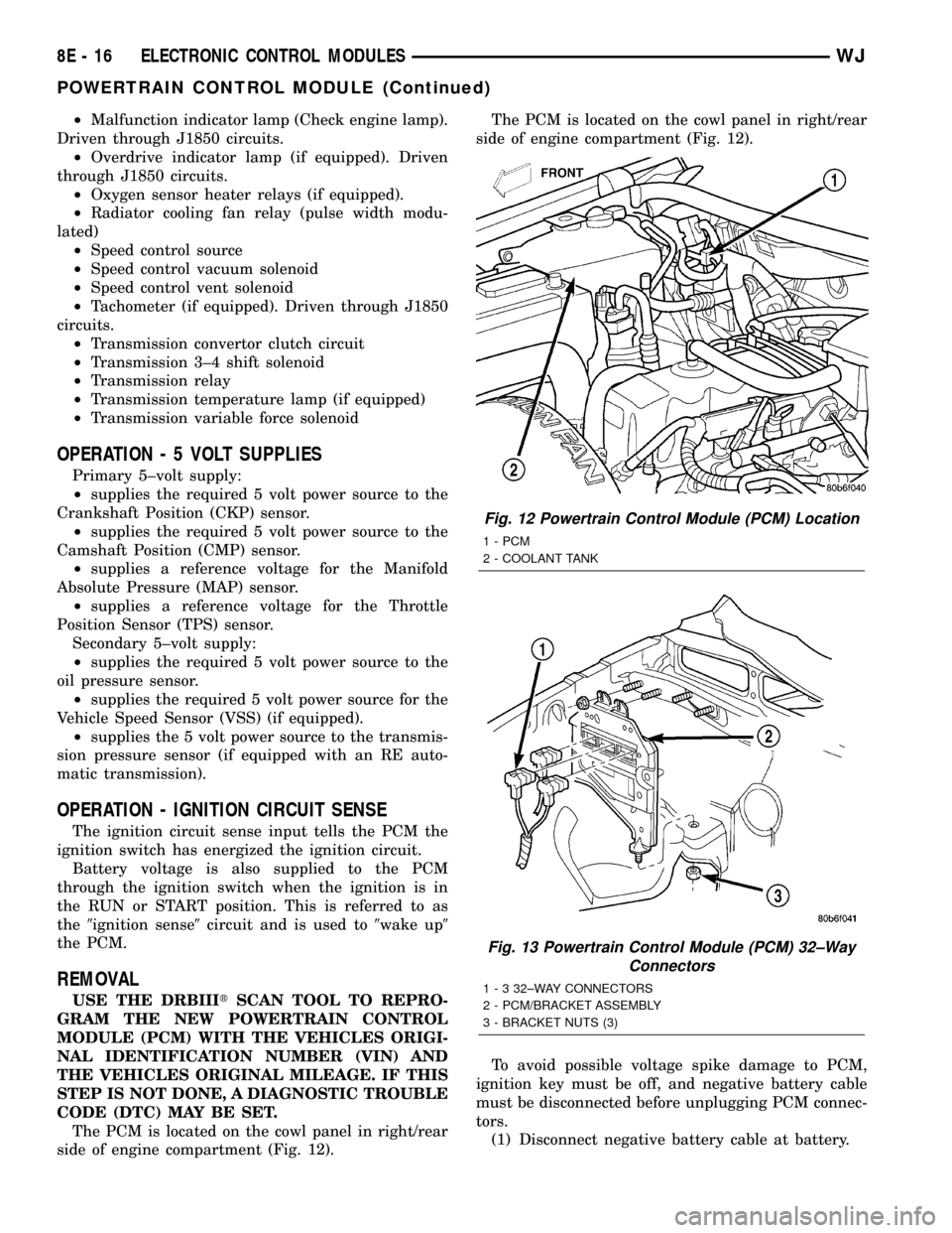
The PCM is located on the cowl panel in right/rear
side of engine compartment (Fig. 12).The PCM is located on the cowl panel in right/rear
side of engine compartment (Fig. 12).
To avoid possible voltage spike damage to PCM,
ignition key must be off, and negative battery cable
must be disconnected before unplugging PCM connec-
tors.
(1) Disconnect negative battery cable at battery.
Fig. 12 Powertrain Control Module (PCM) Location
1 - PCM
2 - COOLANT TANK
Fig. 13 Powertrain Control Module (PCM) 32±Way
Connectors
1 - 3 32±WAY CONNECTORS
2 - PCM/BRACKET ASSEMBLY
3 - BRACKET NUTS (3)
8E - 16 ELECTRONIC CONTROL MODULESWJ
POWERTRAIN CONTROL MODULE (Continued)
Page 330 of 2199
Certain mechanical failures within the input clutch
assembly can cause inadequate or out-of-range ele-
ment volumes. Also, defective Input/Output Speed
Sensors and wiring can cause these conditions. The
following chart identifies the appropriate clutch vol-
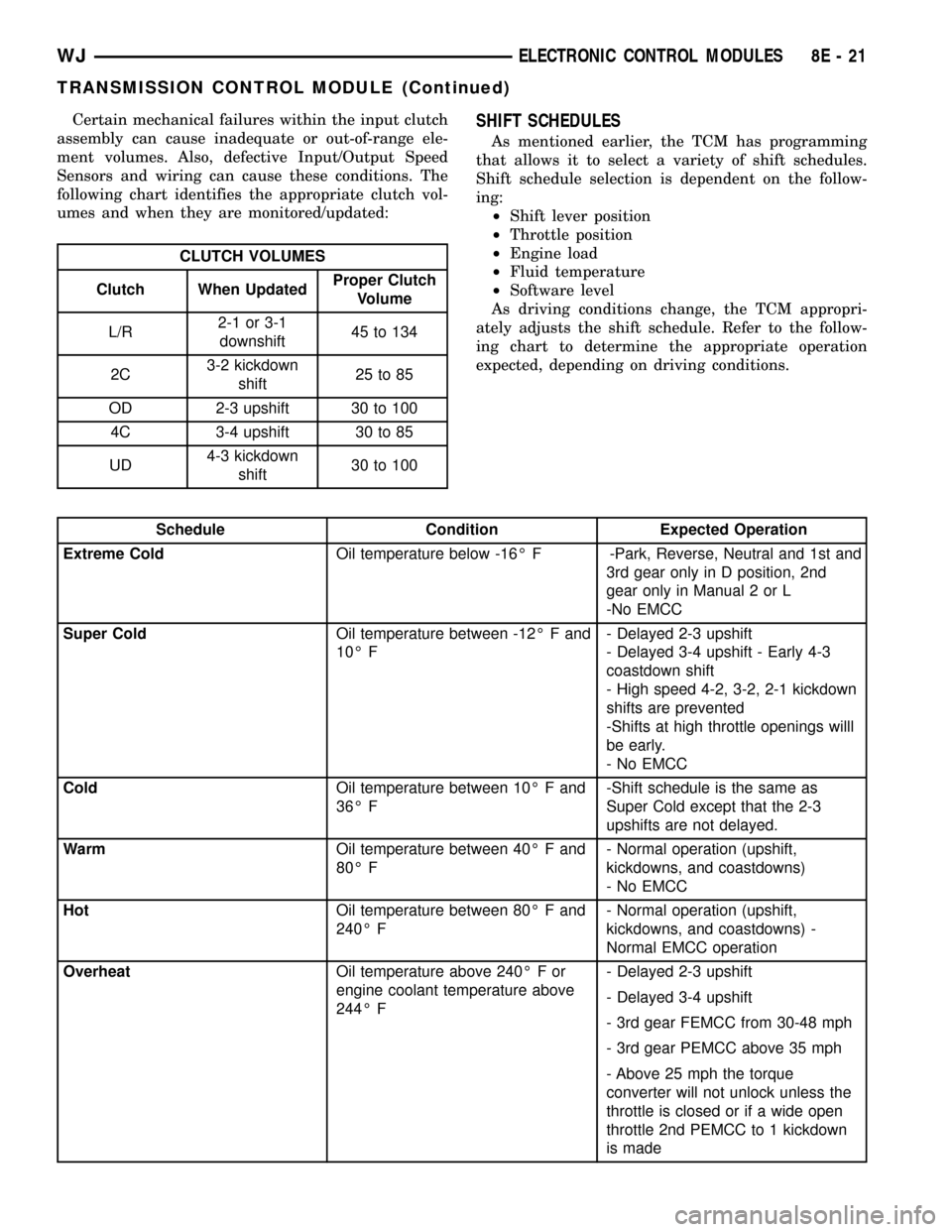
umes and when they are monitored/updated:
CLUTCH VOLUMES
Clutch When UpdatedProper Clutch
Volume
L/R2-1 or 3-1
downshift45 to 134
2C3-2 kickdown
shift25 to 85
OD 2-3 upshift 30 to 100
4C 3-4 upshift 30 to 85
UD4-3 kickdown
shift30 to 100
SHIFT SCHEDULES
As mentioned earlier, the TCM has programming
that allows it to select a variety of shift schedules.
Shift schedule selection is dependent on the follow-
ing:
²Shift lever position
²Throttle position
²Engine load
²Fluid temperature
²Software level
As driving conditions change, the TCM appropri-
ately adjusts the shift schedule. Refer to the follow-
ing chart to determine the appropriate operation
expected, depending on driving conditions.
Schedule Condition Expected Operation
Extreme ColdOil temperature below -16É F -Park, Reverse, Neutral and 1st and
3rd gear only in D position, 2nd
gear only in Manual 2 or L
-No EMCC
Super ColdOil temperature between -12É F and
10É F- Delayed 2-3 upshift
- Delayed 3-4 upshift - Early 4-3
coastdown shift
- High speed 4-2, 3-2, 2-1 kickdown
shifts are prevented
-Shifts at high throttle openings willl
be early.
- No EMCC
ColdOil temperature between 10É F and
36É F-Shift schedule is the same as
Super Cold except that the 2-3
upshifts are not delayed.
WarmOil temperature between 40É F and
80É F- Normal operation (upshift,
kickdowns, and coastdowns)
- No EMCC
HotOil temperature between 80É F and
240É F- Normal operation (upshift,
kickdowns, and coastdowns) -
Normal EMCC operation
OverheatOil temperature above 240É F or
engine coolant temperature above
244É F- Delayed 2-3 upshift
- Delayed 3-4 upshift
- 3rd gear FEMCC from 30-48 mph
- 3rd gear PEMCC above 35 mph
- Above 25 mph the torque
converter will not unlock unless the
throttle is closed or if a wide open
throttle 2nd PEMCC to 1 kickdown
is made
WJELECTRONIC CONTROL MODULES 8E - 21
TRANSMISSION CONTROL MODULE (Continued)
Page 331 of 2199
STANDARD PROCEDURE
STANDARD PROCEDURE - TCM QUICK LEARN
The quick learn procedure requires the use of the
DRBIIItscan tool.
This program allows the electronic transmission
system to recalibrate itself. This will provide the
proper transmission operation. The quick learn pro-
cedure should be performed if any of the following
procedures are performed:
²Transmission Assembly Replacement
²Transmission Control Module Replacement
²Solenoid Pack Replacement
²Clutch Plate and/or Seal Replacement
²Valve Body Replacement or ReconditionTo perform the Quick Learn Procedure, the follow-
ing conditions must be met:
²The brakes must be applied
²The engine speed must be above 500 rpm
²The throttle angle (TPS) must be less than 3
degrees
²The shift lever position must stay in PARK until
prompted to shift to overdrive
²The shift lever position must stay in overdrive
after the Shift to Overdrive prompt until the DRBt
indicates the procedure is complete
²The calculated oil temperature must be above
60É and below 200É
8E - 22 ELECTRONIC CONTROL MODULESWJ
TRANSMISSION CONTROL MODULE (Continued)
Page 361 of 2199
OPERATION
The starting system components form two separate
circuits. A high-amperage feed circuit that feeds the
starter motor between 150 and 350 amperes, and a
low-amperage control circuit that operates on less
than 20 amperes. The high-amperage feed circuit
components include the battery, the battery cables,
the contact disc portion of the starter solenoid, and
the starter motor. The low-amperage control circuit
components include the ignition switch, the park/
neutral position switch, the starter relay, the electro-
magnetic windings of the starter solenoid, and the
connecting wire harness components.
Battery voltage is supplied through the low-amper-
age control circuit to the coil battery terminal of the
starter relay when the ignition switch is turned to
the momentary Start position. The park/neutral posi-
tion switch is installed in series between the starter
relay coil ground terminal and ground. This normally
open switch prevents the starter relay from being
energized and the starter motor from operating
unless the automatic transmission gear selector is in
the Neutral or Park positions.
When the starter relay coil is energized, the nor-
mally open relay contacts close. The relay contacts
connect the relay common feed terminal to the relay
normally open terminal. The closed relay contacts
energize the starter solenoid coil windings.
The energized solenoid pull-in coil pulls in the sole-
noid plunger. The solenoid plunger pulls the shift
lever in the starter motor. This engages the starter
overrunning clutch and pinion gear with the starter
ring gear on the automatic transmission torque con-
verter drive plate.
As the solenoid plunger reaches the end of its
travel, the solenoid contact disc completes the high-
amperage starter feed circuit and energizes the sole-
noid plunger hold-in coil. Current now flows between
the solenoid battery terminal and the starter motor,
energizing the starter.Once the engine starts, the overrunning clutch pro-
tects the starter motor from damage by allowing the
starter pinion gear to spin faster than the pinion
shaft. When the driver releases the ignition switch to
the On position, the starter relay coil is de-energized.
This causes the relay contacts to open. When the
relay contacts open, the starter solenoid plunger
hold-in coil is de-energized.
When the solenoid plunger hold-in coil is de-ener-
gized, the solenoid plunger return spring returns the
plunger to its relaxed position. This causes the con-
tact disc to open the starter feed circuit, and the shift
lever to disengage the overrunning clutch and pinion
gear from the starter ring gear.
DIAGNOSIS AND TESTING - STARTING
SYSTEM
The battery, starting, and charging systems oper-
ate with one another, and must be tested as a com-
plete system. In order for the vehicle to start and
charge properly, all of the components involved in
these systems must perform within specifications.
Group 8A covers the Battery, Group 8B covers the
Starting Systems, and Group 8C covers the Charging
System. We have separated these systems to make it
easier to locate the information you are seeking
within this Service Manual. However, when attempt-
ing to diagnose any of these systems, it is important
that you keep their interdependency in mind.
The diagnostic procedures used in these groups
include the most basic conventional diagnostic meth-
ods, to the more sophisticated On-Board Diagnostics
(OBD) built into the Powertrain Control Module
(PCM). Use of an induction-type milliampere amme-
ter, volt/ohmmeter, battery charger, carbon pile rheo-
stat (load tester), and 12-volt test lamp may be
required.
All OBD-sensed systems are monitored by the
PCM. Each monitored circuit is assigned a Diagnos-
tic Trouble Code (DTC). The PCM will store a DTC in
electronic memory for any failure it detects. Refer to
On-Board Diagnostic Test For Charging System
in the Diagnosis and Testing section of Group 8C -
Charging System for more information.
8F - 30 STARTINGWJ
STARTING (Continued)
Page 367 of 2199
OPERATION
These starter motors are equipped with a plane-
tary gear reduction (intermediate transmission) sys-
tem. The planetary gear reduction system consists of
a gear that is integral to the output end of the elec-
tric motor armature shaft that is in continual
engagement with a larger gear that is splined to the
input end of the starter pinion gear shaft. This fea-
ture makes it possible to reduce the dimensions of
the starter. At the same time, it allows higher arma-
ture rotational speed and delivers increased torque
through the starter pinion gear to the starter ring
gear.
The starter motors for both engines are activated
by an integral heavy duty starter solenoid switch
mounted to the overrunning clutch housing. This
electromechanical switch connects and disconnects
the feed of battery voltage to the starter motor and
actuates a shift fork that engages and disengages the
starter pinion gear with the starter ring gear.
Both starter motors use an overrunning clutch and
starter pinion gear unit to engage and drive a starter
ring gear that is integral to the torque converter
drive plate mounted on the rear crankshaft flange.
DIAGNOSIS AND TESTING - STARTER MOTOR
Correct starter motor operation can be confirmed
by performing the following free running bench test.
This test can only be performed with the starter
motor removed from the vehicle. Refer toStarting
Systemin the Specifications section of this group for
the starter motor specifications.
(1) Remove the starter motor from the vehicle.
Refer toStarter Motorin the Removal and Instal-
lation section of this group for the procedures.
(2) Mount the starter motor securely in a soft-
jawed bench vise. The vise jaws should be clamped
on the mounting flange of the starter motor. Never
clamp on the starter motor by the field frame.
(3) Connect a suitable volt-ampere tester and a
12-volt battery to the starter motor in series, and set
the ammeter to the 100 ampere scale. See the
instructions provided by the manufacturer of the
volt-ampere tester being used.
(4) Install a jumper wire from the solenoid termi-
nal to the solenoid battery terminal. The starter
motor should operate. If the starter motor fails to
operate, replace the faulty starter motor assembly.
(5) Adjust the carbon pile load of the tester to
obtain the free running test voltage. Refer toStart-
ing Systemin the Specifications section of this
group for the starter motor free running test voltage
specifications.
(6) Note the reading on the ammeter and compare
this reading to the free running test maximum
amperage draw. Refer toStarting Systemin theSpecifications section of this group for the starter
motor free running test maximum amperage draw
specifications.
(7) If the ammeter reading exceeds the maximum
amperage draw specification, replace the faulty
starter motor assembly.
STARTER SOLENOID
This test can only be performed with the starter
motor removed from the vehicle.
(1) Remove the starter motor from the vehicle.
Refer toStarter Motorin the Removal and Instal-
lation section of this group for the procedures.
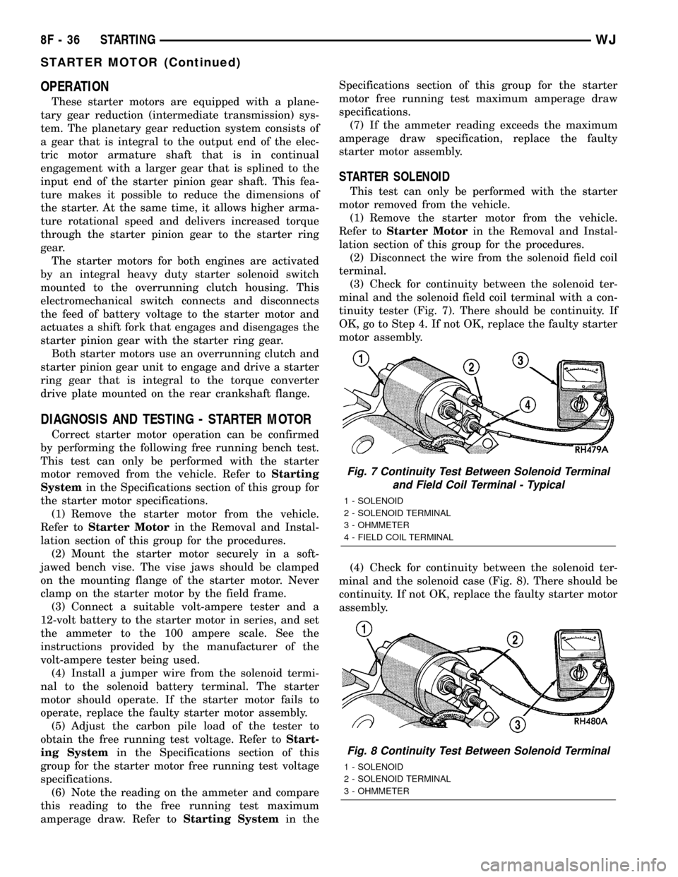
(2) Disconnect the wire from the solenoid field coil
terminal.
(3) Check for continuity between the solenoid ter-
minal and the solenoid field coil terminal with a con-
tinuity tester (Fig. 7). There should be continuity. If
OK, go to Step 4. If not OK, replace the faulty starter
motor assembly.
(4) Check for continuity between the solenoid ter-
minal and the solenoid case (Fig. 8). There should be
continuity. If not OK, replace the faulty starter motor
assembly.
Fig. 7 Continuity Test Between Solenoid Terminal
and Field Coil Terminal - Typical
1 - SOLENOID
2 - SOLENOID TERMINAL
3 - OHMMETER
4 - FIELD COIL TERMINAL
Fig. 8 Continuity Test Between Solenoid Terminal
1 - SOLENOID
2 - SOLENOID TERMINAL
3 - OHMMETER
8F - 36 STARTINGWJ
STARTER MOTOR (Continued)
Page 369 of 2199
(8) Remove the starter motor from the engine com-
partment.
INSTALLATION
(1) Position the starter motor in the engine com-
partment.
(2) Reconnect the solenoid terminal wire harness
connector to the connector receptacle on the starter
solenoid. Always support the starter motor during
this process, do not let the starter motor hang from
the wire harness.
(3) Install the battery cable eyelet onto the sole-
noid battery terminal. Always support the starter
motor during this process, do not let the starter
motor hang from the wire harness.
(4) Install and tighten the nut that secures the
battery cable eyelet to the solenoid battery terminal.
Tighten the nut to 11.3 N´m (100 in. lbs.). Always
support the starter motor during this process, do not
let the starter motor hang from the wire harness.
(5) Position the starter motor to the front of the
automatic transmission torque converter housing and
loosely install both the upper and lower mounting
screws.
(6) Tighten the lower (forward facing) starter
motor mounting screw. On 4.0L engines, tighten the
screw to 41 N´m (30 ft. lbs.). On 4.7L engines, tighten
the screw to 54 N´m (40 ft. lbs.).(7) Tighten the upper (rearward facing) starter
mounting screw. Tighten the screw to 54 N´m (40 ft.
lbs.).
(8) Lower the vehicle.
(9) Reconnect the battery negative cable.
STARTER MOTOR RELAY
DESCRIPTION
The starter relay is an electromechanical device
that switches battery current to the pull-in coil of the
starter solenoid when the ignition switch is turned to
the Start position. The starter relay is located in the
Power Distribution Center (PDC), in the engine com-
partment. See the fuse and relay layout label affixed
to the inside surface of the PDC cover for starter
relay identification and location.
The starter relay is a International Standards
Organization (ISO) micro-relay. Relays conforming to
the ISO specifications have common physical dimen-
sions, current capacities, terminal patterns, and ter-
minal functions. The ISO micro-relay terminal
functions are the same as a conventional ISO relay.
However, the ISO micro-relay terminal pattern (or
footprint) is different, the current capacity is lower,
and the physical dimensions are smaller than those
of the conventional ISO relay.
The starter relay cannot be repaired or adjusted
and, if faulty or damaged, it must be replaced.
OPERATION
The ISO relay consists of an electromagnetic coil, a
resistor or diode, and three (two fixed and one mov-
able) electrical contacts. The movable (common feed)
relay contact is held against one of the fixed contacts
(normally closed) by spring pressure. When the elec-
tromagnetic coil is energized, it draws the movable
contact away from the normally closed fixed contact,
and holds it against the other (normally open) fixed
contact.
When the electromagnetic coil is de-energized,
spring pressure returns the movable contact to the
normally closed position. The resistor or diode is con-
nected in parallel with the electromagnetic coil in the
relay, and helps to dissipate voltage spikes that are
produced when the coil is de-energized.
DIAGNOSIS AND TESTING - STARTER RELAY
The starter relay (Fig. 13) is located in the Power
Distribution Center (PDC), in the engine compart-
ment. Refer to the fuse and relay layout label affixed
to the underside of the PDC cover for starter relay
identification and location. For complete circuit dia-
grams, refer toStarting Systemin the Contents of
Group 8W - Wiring Diagrams.
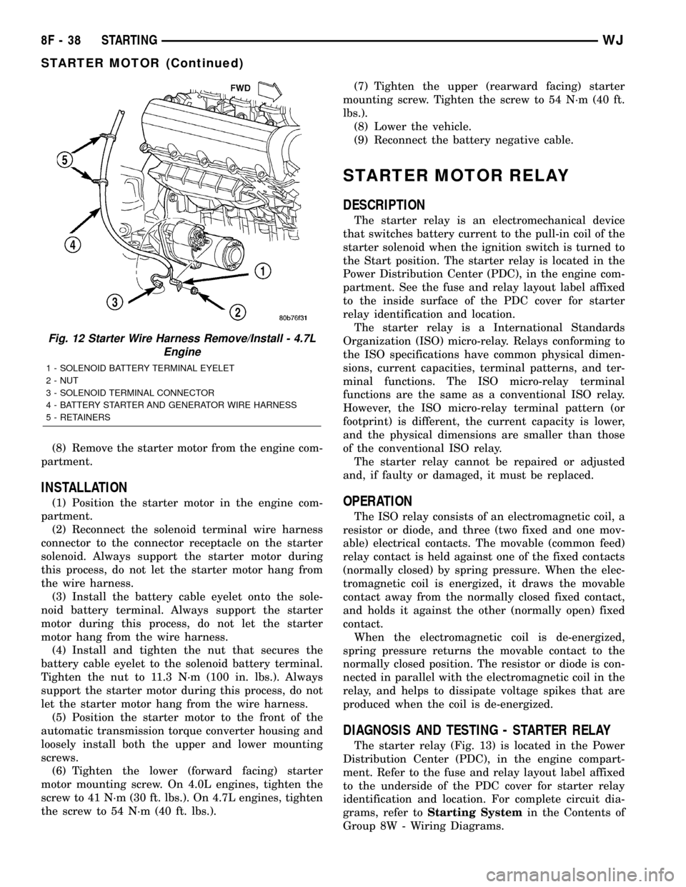
Fig. 12 Starter Wire Harness Remove/Install - 4.7L
Engine
1 - SOLENOID BATTERY TERMINAL EYELET
2 - NUT
3 - SOLENOID TERMINAL CONNECTOR
4 - BATTERY STARTER AND GENERATOR WIRE HARNESS
5 - RETAINERS
8F - 38 STARTINGWJ
STARTER MOTOR (Continued)
Page 370 of 2199
(1) Remove the starter relay from the PDC. Refer
toStarter Relayin the Removal and Installation
section of this group for the procedures.
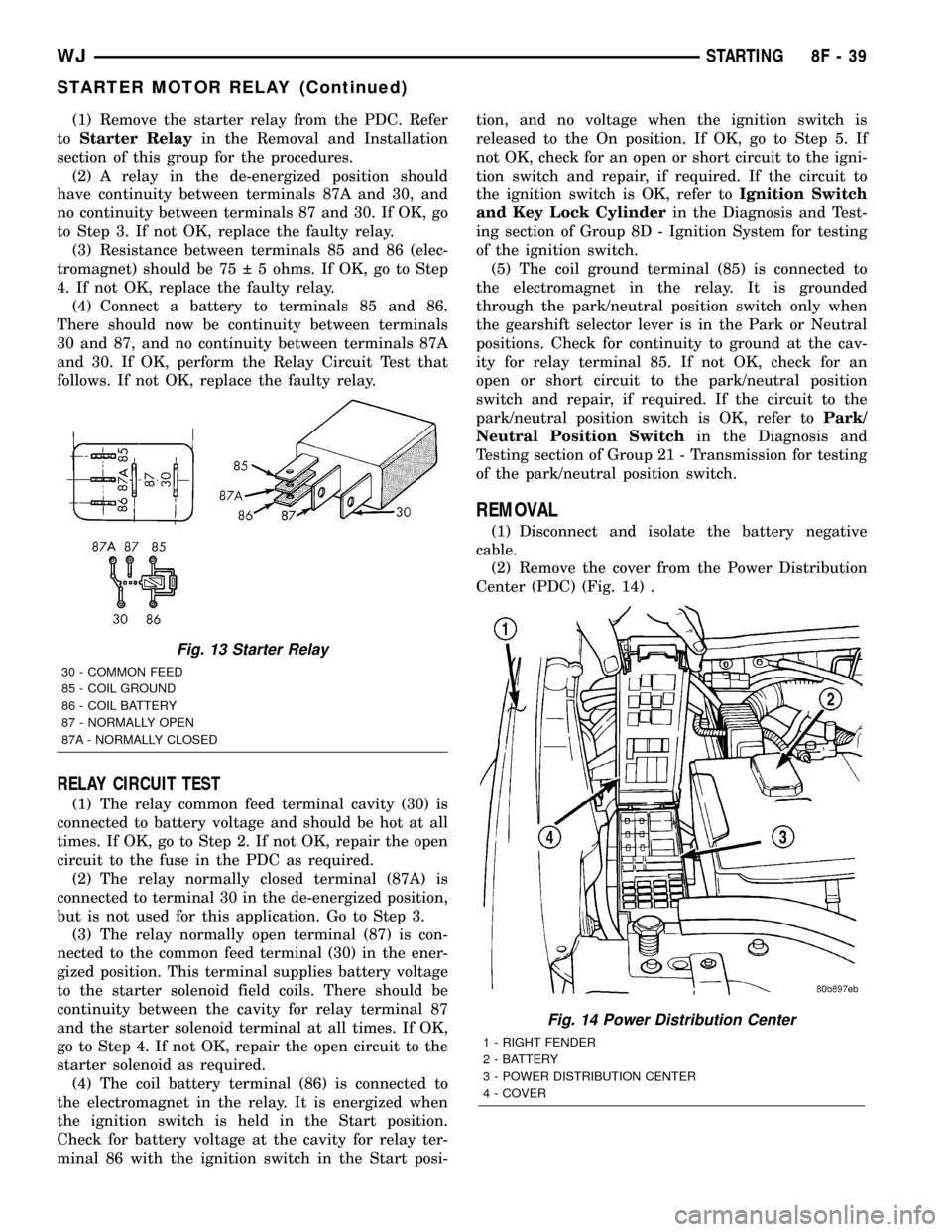
(2) A relay in the de-energized position should
have continuity between terminals 87A and 30, and
no continuity between terminals 87 and 30. If OK, go
to Step 3. If not OK, replace the faulty relay.
(3) Resistance between terminals 85 and 86 (elec-
tromagnet) should be 75 5 ohms. If OK, go to Step
4. If not OK, replace the faulty relay.
(4) Connect a battery to terminals 85 and 86.
There should now be continuity between terminals
30 and 87, and no continuity between terminals 87A
and 30. If OK, perform the Relay Circuit Test that
follows. If not OK, replace the faulty relay.
RELAY CIRCUIT TEST
(1) The relay common feed terminal cavity (30) is
connected to battery voltage and should be hot at all
times. If OK, go to Step 2. If not OK, repair the open
circuit to the fuse in the PDC as required.
(2) The relay normally closed terminal (87A) is
connected to terminal 30 in the de-energized position,
but is not used for this application. Go to Step 3.
(3) The relay normally open terminal (87) is con-
nected to the common feed terminal (30) in the ener-
gized position. This terminal supplies battery voltage
to the starter solenoid field coils. There should be
continuity between the cavity for relay terminal 87
and the starter solenoid terminal at all times. If OK,
go to Step 4. If not OK, repair the open circuit to the
starter solenoid as required.
(4) The coil battery terminal (86) is connected to
the electromagnet in the relay. It is energized when
the ignition switch is held in the Start position.
Check for battery voltage at the cavity for relay ter-
minal 86 with the ignition switch in the Start posi-tion, and no voltage when the ignition switch is
released to the On position. If OK, go to Step 5. If
not OK, check for an open or short circuit to the igni-
tion switch and repair, if required. If the circuit to
the ignition switch is OK, refer toIgnition Switch
and Key Lock Cylinderin the Diagnosis and Test-
ing section of Group 8D - Ignition System for testing
of the ignition switch.
(5) The coil ground terminal (85) is connected to
the electromagnet in the relay. It is grounded
through the park/neutral position switch only when
the gearshift selector lever is in the Park or Neutral
positions. Check for continuity to ground at the cav-
ity for relay terminal 85. If not OK, check for an
open or short circuit to the park/neutral position
switch and repair, if required. If the circuit to the
park/neutral position switch is OK, refer toPark/
Neutral Position Switchin the Diagnosis and
Testing section of Group 21 - Transmission for testing
of the park/neutral position switch.
REMOVAL
(1) Disconnect and isolate the battery negative
cable.
(2) Remove the cover from the Power Distribution
Center (PDC) (Fig. 14) .
Fig. 13 Starter Relay
30 - COMMON FEED
85 - COIL GROUND
86 - COIL BATTERY
87 - NORMALLY OPEN
87A - NORMALLY CLOSED
Fig. 14 Power Distribution Center
1 - RIGHT FENDER
2 - BATTERY
3 - POWER DISTRIBUTION CENTER
4 - COVER
WJSTARTING 8F - 39
STARTER MOTOR RELAY (Continued)
Page 418 of 2199
EMIC also uses several hard wired inputs in order to
perform its many functions. The EMIC module incor-
porates a blue-green digital Vacuum Fluorescent Dis-
play (VFD) for displaying odometer and trip
odometer information.
The EMIC houses six analog gauges and has pro-
visions for up to twenty indicators (Fig. 2). The
EMIC includes the following analog gauges:
²Coolant Temperature Gauge
²Fuel Gauge
²Oil Pressure Gauge
²Speedometer
²Tachometer
²Voltage Gauge
Some of the EMIC indicators are automatically
configured when the EMIC is connected to the vehi-
cle electrical system for compatibility with certain
optional equipment or equipment required for regula-
tory purposes in certain markets. While each EMIC
may have provisions for indicators to support every
available option, the configurable indicators will not
be functional in a vehicle that does not have the
equipment that an indicator supports. The EMIC
includes provisions for the following indicators (Fig.
2):
²Airbag Indicator (with Airbags only)
²Antilock Brake System (ABS) Indicator
²Brake Indicator
²Check Gauges Indicator
²Coolant Low Indicator (with Diesel Engine
only)
²Cruise Indicator
²Four-Wheel Drive Part Time Indicator
(with Selec-Trac NVG-242 Transfer Case only)
²Front Fog Lamp Indicator (with Front Fog
Lamps only)
²High Beam Indicator
²Low Fuel Indicator
²Malfunction Indicator Lamp (MIL)
²Overdrive-Off Indicator (except Diesel
Engine)
²Rear Fog Lamp Indicator (with Rear Fog
Lamps only)
²Seatbelt Indicator
²Sentry Key Immobilizer System (SKIS)
Indicator
²Transmission Overtemp Indicator (except
Diesel Engine)²Turn Signal (Right and Left) Indicators
²Wait-To-Start Indicator (with Diesel Engine
only)
²Water-In-Fuel Indicator (with Diesel Engine
only)
Many indicators in the EMIC are illuminated by a
dedicated Light Emitting Diode (LED) that is sol-
dered onto the EMIC electronic circuit board. The
LEDs are not available for service replacement and,
if damaged or faulty, the entire EMIC must be
replaced. Base cluster illumination is accomplished
by dimmable incandescent back lighting, which illu-
minates the gauges for visibility when the exterior
lighting is turned on. Premium cluster illumination
is accomplished by a dimmable electro-luminescent
lamp that is serviced only as a unit with the EMIC.
Each of the incandescent bulbs is secured by an inte-
gral bulb holder to the electronic circuit board from
the back of the cluster housing. The incandescent
bulb/bulb holder units are available for service
replacement.
Hard wired circuitry connects the EMIC to the
electrical system of the vehicle. These hard wired cir-
cuits are integral to several wire harnesses, which
are routed throughout the vehicle and retained by
many different methods. These circuits may be con-
nected to each other, to the vehicle electrical system
and to the EMIC through the use of a combination of
soldered splices, splice block connectors, and many
different types of wire harness terminal connectors
and insulators. Refer to the appropriate wiring infor-
mation. The wiring information includes wiring dia-
grams, proper wire and connector repair procedures,
further details on wire harness routing and reten-
tion, as well as pin-out and location views for the
various wire harness connectors, splices and grounds.
The EMIC modules for this model are serviced only
as complete units. The EMIC module cannot be
adjusted or repaired. If a gauge, an LED indicator,
the VFD, the electronic circuit board, the circuit
board hardware, the cluster overlay, the electro-lumi-
nescent lamp (premium model only) or the EMIC
housing are damaged or faulty, the entire EMIC mod-
ule must be replaced. The cluster lens, hood and
mask unit and the individual incandescent lamp
bulbs with holders are available for service replace-
ment.
WJINSTRUMENT CLUSTER 8J - 3
INSTRUMENT CLUSTER (Continued)