ECU JEEP GRAND CHEROKEE 2003 WJ / 2.G Workshop Manual
[x] Cancel search | Manufacturer: JEEP, Model Year: 2003, Model line: GRAND CHEROKEE, Model: JEEP GRAND CHEROKEE 2003 WJ / 2.GPages: 2199, PDF Size: 76.01 MB
Page 1236 of 2199
CAUTION: Do not remove the wiring and terminals
from the terminal cavities of the faulty PDC relay
cassette at this time. Refer to the Assembly proce-
dure that follows for the proper procedures for
transferring the wiring and terminals to the replace-
ment PDC relay cassette.
ASSEMBLY
POWER DISTRIBUTION CENTER ASSEMBLY
PDC B(+) TERMINAL MODULE INSTALLATION
(1) From the bottom of the PDC housing, align and
insert the B(+) terminal module into the PDC.
(2) From the bottom of the PDC housing, align and
insert the two studs of the PDC B(+) terminal mod-
ule through the bus bar in the PDC.
(3) From the bottom of the PDC housing, press the
B(+) terminal module gently and evenly into the PDC
until both of the latches are fully engaged.
(4) Install the PDC housing lower cover.
RELAY WEDGE INSTALLATION
(1) From the top of the PDC housing, align and
insert the PDC relay wedge latch arms into the cor-
rect cavities in the relay cassette.
(2) Gently and evenly press the PDC relay wedge
down into the relay cassette until both of the latches
are fully engaged.
(3) Install each of the removed relays into the
proper cavities of the PDC relay wedge.
(4) Install the PDC housing lower cover.
RELAY CASSETTE INSTALLATION
(1) Move the faulty PDC relay cassette with its
wiring away from the bottom of the PDC housing far
enough to allow the replacement relay cassette to be
installed into the PDC.
(2) Using the faulty relay cassette as a guide, be
certain that the replacement relay cassette is cor-
rectly oriented before installing it into the PDC hous-
ing.
(3) From the bottom of the PDC housing, align and
insert the replacement relay cassette into the PDC.
Press the relay cassette up into the PDC until both
of the latches are fully engaged.
CAUTION: Proper care must be taken to be certain
that the wiring and terminals from the faulty PDC
relay cassette are installed in the correct terminal
cavities of the replacement relay cassette. To pre-
vent mistakes it is recommended that the wiring
and terminals be removed from the faulty relay cas-
sette one cavity at a time, repaired or spliced as
necessary, then installed securely into the correctcavity of the replacement relay cassette. If you are
not absolutely certain into which cavity a terminal
should be installed, refer to Power Distribution in
the index of this service manual for the location of
complete circuit diagrams covering the PDC.
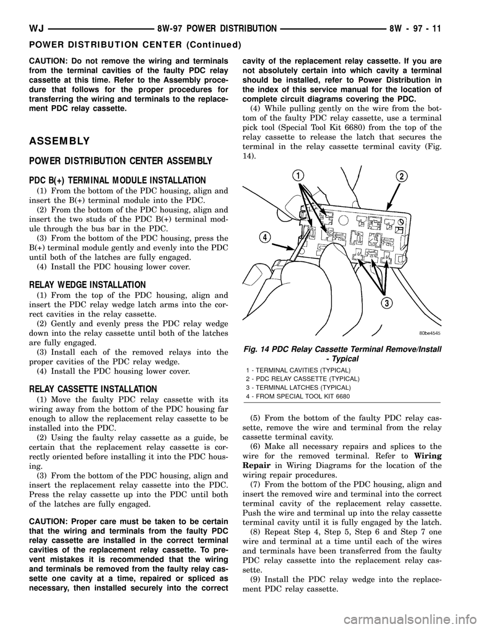
(4) While pulling gently on the wire from the bot-
tom of the faulty PDC relay cassette, use a terminal
pick tool (Special Tool Kit 6680) from the top of the
relay cassette to release the latch that secures the
terminal in the relay cassette terminal cavity (Fig.
14).
(5) From the bottom of the faulty PDC relay cas-
sette, remove the wire and terminal from the relay
cassette terminal cavity.
(6) Make all necessary repairs and splices to the
wire for the removed terminal. Refer toWiring
Repairin Wiring Diagrams for the location of the
wiring repair procedures.
(7) From the bottom of the PDC housing, align and
insert the removed wire and terminal into the correct
terminal cavity of the replacement relay cassette.
Push the wire and terminal up into the relay cassette
terminal cavity until it is fully engaged by the latch.
(8) Repeat Step 4, Step 5, Step 6 and Step 7 one
wire and terminal at a time until each of the wires
and terminals have been transferred from the faulty
PDC relay cassette into the replacement relay cas-
sette.
(9) Install the PDC relay wedge into the replace-
ment PDC relay cassette.
Fig. 14 PDC Relay Cassette Terminal Remove/Install
- Typical
1 - TERMINAL CAVITIES (TYPICAL)
2 - PDC RELAY CASSETTE (TYPICAL)
3 - TERMINAL LATCHES (TYPICAL)
4 - FROM SPECIAL TOOL KIT 6680
WJ8W-97 POWER DISTRIBUTION 8W - 97 - 11
POWER DISTRIBUTION CENTER (Continued)
Page 1237 of 2199

PDC LOWER COVER INSTALLATION
(1) Align the PDC housing lower cover on the bot-
tom of the PDC.
(2) Evenly press the lower cover into place until
latches are fully engaged.
(3) Where the right headlamp and dash harness
enters the PDC, tape the harness securely to the
trough formation on the PDC lower cover.
(4) Install the PDC in its mounting location on the
battery support.
(5) Install the battery wire harness over the two
PDC B+ terminal studs. Torque the nuts to 11.3 N´m
(100 in. lbs.).
(6) Install the battery. Refer to Battery System for
the procedure.
(7) Install the PDC cover.
INSTALLATION
The Power Distribution Center (PDC) main hous-
ing unit, the PDC fuse wedges and the PDC bus bars
cannot be repaired and are only serviced as a unit
with the right headlamp and dash wire harness. If
the PDC main housing unit, the fuse wedges or the
bus bars are faulty or damaged, the entire PDC and
right headlamp and dash wire harness unit must be
replaced.
(1) Position the PDC and the right headlamp and
dash wire harness unit in the engine compartment.
(2) Engage the PDC housing mounts with the
stanchions of the battery support and push the unit
downward until the mount latches fully engage the
mounting tabs on the stanchions.
(3) Install the two-holed eyelet of the battery wire
harness PDC take outs onto the two PDC B(+) termi-
nal studs.
(4) Install and tighten the nuts that secure the
eyelet of the battery wire harness PDC take outs to
the B(+) terminal studs. Tighten the nuts to 11.3
N´m (100 in. lbs.).
(5) Engage each of the retainers that secure the
right headlamp and dash wire harness to the vehicle
body and chassis components. Refer toConnector
Locationsin Wiring Diagrams for the location of
more information on the right headlamp and dash
wire harness retainer locations.
(6) Install all of the fasteners that secure each of
the right headlamp and dash wire harness ground
eyelets to the vehicle body and chassis components.
Refer toConnector Locationsin Wiring Diagrams
for the location of more information on the ground
eyelet locations.
(7) Reconnect each of the right headlamp and dash
wire harness connectors. Refer toConnector Loca-
tionsin Wiring Diagrams for the location of more
information on the right headlamp and dash wire
harness connector locations. For connectors securedwith screws, tighten the screws to 4.3 N´m (38 in.
lbs.).
(8) Reconnect the battery negative cable.
POWER OUTLET
DESCRIPTION - FRONT POWER OUTLET
An accessory power outlet is standard equipment
on this model. The power outlet is installed in the
instrument panel center lower bezel, which is located
near the bottom of the instrument panel center stack
area, below the heater and air conditioner controls.
The power outlet base is secured by a snap fit within
the center lower bezel. A hinged door with an over-
center spring flips closed to conceal and protect the
power outlet base when the power outlet is not being
used, and flips open below the center lower bezel
while the power outlet is in use.
The power outlet receptacle unit and the power
outlet door are each available for service replace-
ment.
OPERATION - FRONT POWER OUTLET
The power outlet base or receptacle shell is con-
nected to ground, and an insulated contact in the
bottom of the shell is connected to battery current.
The power outlet receives battery voltage from a fuse
in the junction block at all times.
While the power outlet is very similar to a cigar
lighter base unit, it does not include the two small
spring-clip retainers inside the bottom of the recepta-
cle shell that are used to secure the cigar lighter
heating element to the insulated contact.
DIAGNOSIS AND TESTING - POWER OUTLET
For complete circuit diagrams, refer toHorn/Ci-
gar Lighter/Power Outletin Wiring Diagrams.
WARNING: REFER TO RESTRAINTS BEFORE
ATTEMPTING ANY STEERING WHEEL, STEERING
COLUMN, OR INSTRUMENT PANEL COMPONENT
DIAGNOSIS OR SERVICE. FAILURE TO TAKE THE
PROPER PRECAUTIONS COULD RESULT IN ACCI-
DENTAL AIRBAG DEPLOYMENT AND POSSIBLE
PERSONAL INJURY.
(1) Check the fused B(+) fuse in the junction block.
If OK, go to Step 2. If not OK, repair the shorted cir-
cuit or component as required and replace the faulty
fuse.
(2) Check for battery voltage at the fused B(+) fuse
in the junction block. If OK, go to Step 3. If not OK,
repair the open fused B(+) circuit to the Power Dis-
tribution Center (PDC) fuse as required.
(3) Open the power outlet door. Check for continu-
ity between the inside circumference of the power
8W - 97 - 12 8W-97 POWER DISTRIBUTIONWJ
POWER DISTRIBUTION CENTER (Continued)
Page 1238 of 2199
outlet receptacle and a good ground. There should be
continuity. If OK, go to Step 4. If not OK, go to Step
5.
(4) Check for battery voltage at the insulated con-
tact located at the back of the power outlet recepta-
cle. If not OK, go to Step 5.
(5) Disconnect and isolate the battery negative
cable. Remove the instrument panel center lower
bezel. Check for continuity between the ground cir-
cuit cavity of the power outlet wire harness connector
and a good ground. There should be continuity. If
OK, go to Step 6. If not OK, repair the open ground
circuit to ground as required.
(6) Connect the battery negative cable. Check for
battery voltage at the fused B(+) circuit cavity of the
power outlet wire harness connector. If OK, replace
the faulty power outlet receptacle. If not OK, repair
the open fused B(+) circuit to the junction block fuse
as required.
REMOVAL
(1) Disconnect and isolate the battery negative
cable.
(2) Remove the center lower bezel from the instru-
ment panel. Refer toInstrument Panel Center
Lower Bezelin Body for the procedure.
(3) Pull the cigar lighter knob and element or the
protective cap out of the cigar lighter receptacle base,
or open the power outlet door in the instrument
panel center lower bezel.
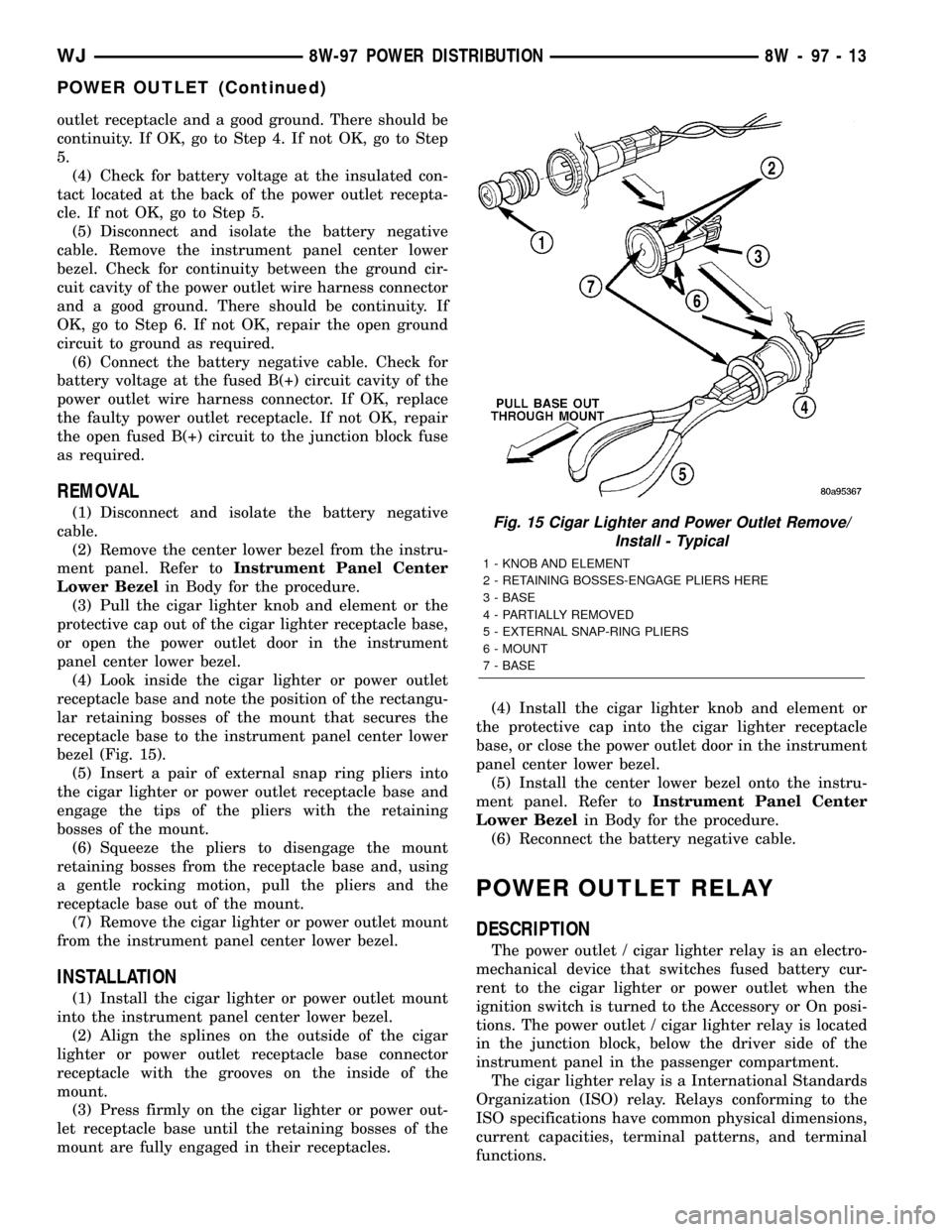
(4) Look inside the cigar lighter or power outlet
receptacle base and note the position of the rectangu-
lar retaining bosses of the mount that secures the
receptacle base to the instrument panel center lower
bezel (Fig. 15).
(5) Insert a pair of external snap ring pliers into
the cigar lighter or power outlet receptacle base and
engage the tips of the pliers with the retaining
bosses of the mount.
(6) Squeeze the pliers to disengage the mount
retaining bosses from the receptacle base and, using
a gentle rocking motion, pull the pliers and the
receptacle base out of the mount.
(7) Remove the cigar lighter or power outlet mount
from the instrument panel center lower bezel.
INSTALLATION
(1) Install the cigar lighter or power outlet mount
into the instrument panel center lower bezel.
(2) Align the splines on the outside of the cigar
lighter or power outlet receptacle base connector
receptacle with the grooves on the inside of the
mount.
(3) Press firmly on the cigar lighter or power out-
let receptacle base until the retaining bosses of the
mount are fully engaged in their receptacles.(4) Install the cigar lighter knob and element or
the protective cap into the cigar lighter receptacle
base, or close the power outlet door in the instrument
panel center lower bezel.
(5) Install the center lower bezel onto the instru-
ment panel. Refer toInstrument Panel Center
Lower Bezelin Body for the procedure.
(6) Reconnect the battery negative cable.
POWER OUTLET RELAY
DESCRIPTION
The power outlet / cigar lighter relay is an electro-
mechanical device that switches fused battery cur-
rent to the cigar lighter or power outlet when the
ignition switch is turned to the Accessory or On posi-
tions. The power outlet / cigar lighter relay is located
in the junction block, below the driver side of the
instrument panel in the passenger compartment.
The cigar lighter relay is a International Standards
Organization (ISO) relay. Relays conforming to the
ISO specifications have common physical dimensions,
current capacities, terminal patterns, and terminal
functions.
Fig. 15 Cigar Lighter and Power Outlet Remove/
Install - Typical
1 - KNOB AND ELEMENT
2 - RETAINING BOSSES-ENGAGE PLIERS HERE
3 - BASE
4 - PARTIALLY REMOVED
5 - EXTERNAL SNAP-RING PLIERS
6 - MOUNT
7 - BASE
WJ8W-97 POWER DISTRIBUTION 8W - 97 - 13
POWER OUTLET (Continued)
Page 1240 of 2199
ground at all times. If not OK, repair the open
ground circuit to ground as required.
REMOVAL
(1) Disconnect and isolate the battery negative
cable.
(2) Remove the steering column opening cover
from the instrument panel. Refer toSteering Col-
umn Opening Coverin Body for the procedure.
(3) The power outlet / cigar lighter relay is located
on the left side of the combination flasher in the
junction block.
(4) Remove the power outlet / cigar lighter relay
from the junction block.
INSTALLATION
(1) Position the power outlet / cigar lighter relay in
the proper receptacle in the junction block.
(2) Align the power outlet / cigar lighter relay ter-
minals with the terminal cavities in the junction
block receptacle.
(3) Push in firmly on the power outlet / cigar
lighter relay until the terminals are fully seated in
the terminal cavities in the junction block receptacle.
(4) Install the steering column opening cover onto
the instrument panel. Refer toSteering Column
Opening Coverin Body for the procedure.
(5) Reconnect the battery negative cable.
IOD WIRE HARNESS
CONNECTOR
DESCRIPTION
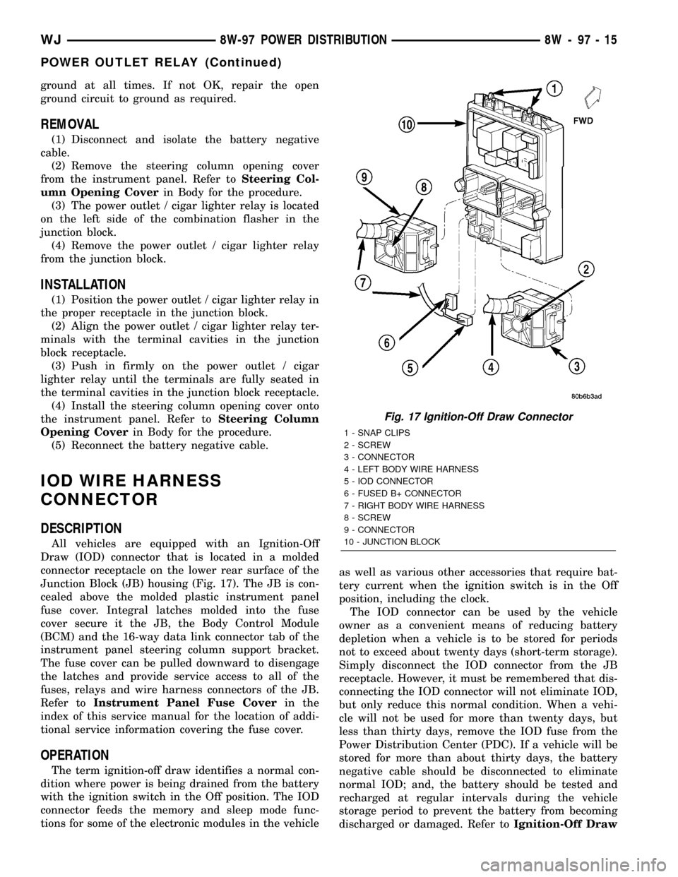
All vehicles are equipped with an Ignition-Off
Draw (IOD) connector that is located in a molded
connector receptacle on the lower rear surface of the
Junction Block (JB) housing (Fig. 17). The JB is con-
cealed above the molded plastic instrument panel
fuse cover. Integral latches molded into the fuse
cover secure it the JB, the Body Control Module
(BCM) and the 16-way data link connector tab of the
instrument panel steering column support bracket.
The fuse cover can be pulled downward to disengage
the latches and provide service access to all of the
fuses, relays and wire harness connectors of the JB.
Refer toInstrument Panel Fuse Coverin the
index of this service manual for the location of addi-
tional service information covering the fuse cover.
OPERATION
The term ignition-off draw identifies a normal con-
dition where power is being drained from the battery
with the ignition switch in the Off position. The IOD
connector feeds the memory and sleep mode func-
tions for some of the electronic modules in the vehicleas well as various other accessories that require bat-
tery current when the ignition switch is in the Off
position, including the clock.
The IOD connector can be used by the vehicle
owner as a convenient means of reducing battery
depletion when a vehicle is to be stored for periods
not to exceed about twenty days (short-term storage).
Simply disconnect the IOD connector from the JB
receptacle. However, it must be remembered that dis-
connecting the IOD connector will not eliminate IOD,
but only reduce this normal condition. When a vehi-
cle will not be used for more than twenty days, but
less than thirty days, remove the IOD fuse from the
Power Distribution Center (PDC). If a vehicle will be
stored for more than about thirty days, the battery
negative cable should be disconnected to eliminate
normal IOD; and, the battery should be tested and
recharged at regular intervals during the vehicle
storage period to prevent the battery from becoming
discharged or damaged. Refer toIgnition-Off Draw
Fig. 17 Ignition-Off Draw Connector
1 - SNAP CLIPS
2 - SCREW
3 - CONNECTOR
4 - LEFT BODY WIRE HARNESS
5 - IOD CONNECTOR
6 - FUSED B+ CONNECTOR
7 - RIGHT BODY WIRE HARNESS
8 - SCREW
9 - CONNECTOR
10 - JUNCTION BLOCK
WJ8W-97 POWER DISTRIBUTION 8W - 97 - 15
POWER OUTLET RELAY (Continued)
Page 1242 of 2199
the vehicle. The power outlet base and mount are
secured by a snap fit within the quarter trim panel.
A plastic protective cap snaps into the power outlet
base when the power outlet is not being used, and
hangs from the power outlet base mount by an inte-
gral bail strap while the power outlet is in use. While
the power outlet is very similar to a cigar lighter
base unit, it does not include the two small spring-
clip retainers inside the bottom of the receptacle
shell that are used to secure the cigar lighter heating
element to the insulated contact.
The power outlet receptacle unit and the accessory
power outlet protective cap are available for service.
The power outlet receptacle cannot be repaired and,
if faulty or damaged, it must be replaced.
OPERATION - REAR POWER OUTLET
The power outlet base or receptacle shell is con-
nected to ground, and an insulated contact in the
bottom of the shell is connected to battery current.
The power outlet receives battery voltage from a fuse
in the Power Distribution Center (PDC) through a
fuse in the Junction Block (JB) at all times. Refer to
Horn/Cigar Lighter/Power Outletin Wiring Dia-
grams for the location of complete rear power outlet
circuit diagrams.
DIAGNOSIS AND TESTING - REAR POWER
OUTLET
Refer toHorn/Cigar Lighter/Power Outletin
Wiring Diagrams for the location of complete rear
power outlet circuit diagrams.
(1) Check the fused B(+) fuse in the Junction
Block (JB). If OK, go to Step 2. If not OK, repair the
shorted circuit or component as required and replace
the faulty fuse.
(2) Check for battery voltage at the fused B(+) fuse
in the JB. If OK, go to Step 3. If not OK, repair the
open fused B(+) circuit to the Power Distribution
Center (PDC) as required.
(3) Remove the plastic protective cap from the rear
power outlet receptacle. Check for continuity between
the inside circumference of the rear power outlet
receptacle and a good ground. There should be conti-
nuity. If OK, go to Step 4. If not OK, go to Step 5.
(4) Check for battery voltage at the insulated con-
tact located at the back of the rear power outlet
receptacle. If not OK, go to Step 5.(5) Disconnect and isolate the battery negative
cable. Remove the rear power outlet from the right
quarter trim panel. Check for continuity between the
ground circuit cavity of the rear power outlet wire
harness connector and a good ground. There should
be continuity. If OK, go to Step 6. If not OK, repair
the open ground circuit to ground as required.
(6) Connect the battery negative cable. Check for
battery voltage at the fused B(+) circuit cavity of the
rear power outlet wire harness connector. If OK,
replace the faulty rear power outlet receptacle base.
If not OK, repair the open fused B(+) circuit to the
JB fuse as required.
REMOVAL
(1) Disconnect and isolate the battery negative
cable.
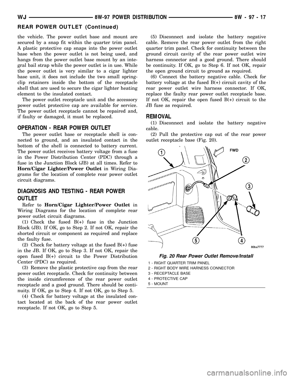
(2) Pull the protective cap out of the rear power
outlet receptacle base (Fig. 20).
Fig. 20 Rear Power Outlet Remove/Install
1 - RIGHT QUARTER TRIM PANEL
2 - RIGHT BODY WIRE HARNESS CONNECTOR
3 - RECEPTACLE BASE
4 - PROTECTIVE CAP
5 - MOUNT
WJ8W-97 POWER DISTRIBUTION 8W - 97 - 17
REAR POWER OUTLET (Continued)
Page 1243 of 2199
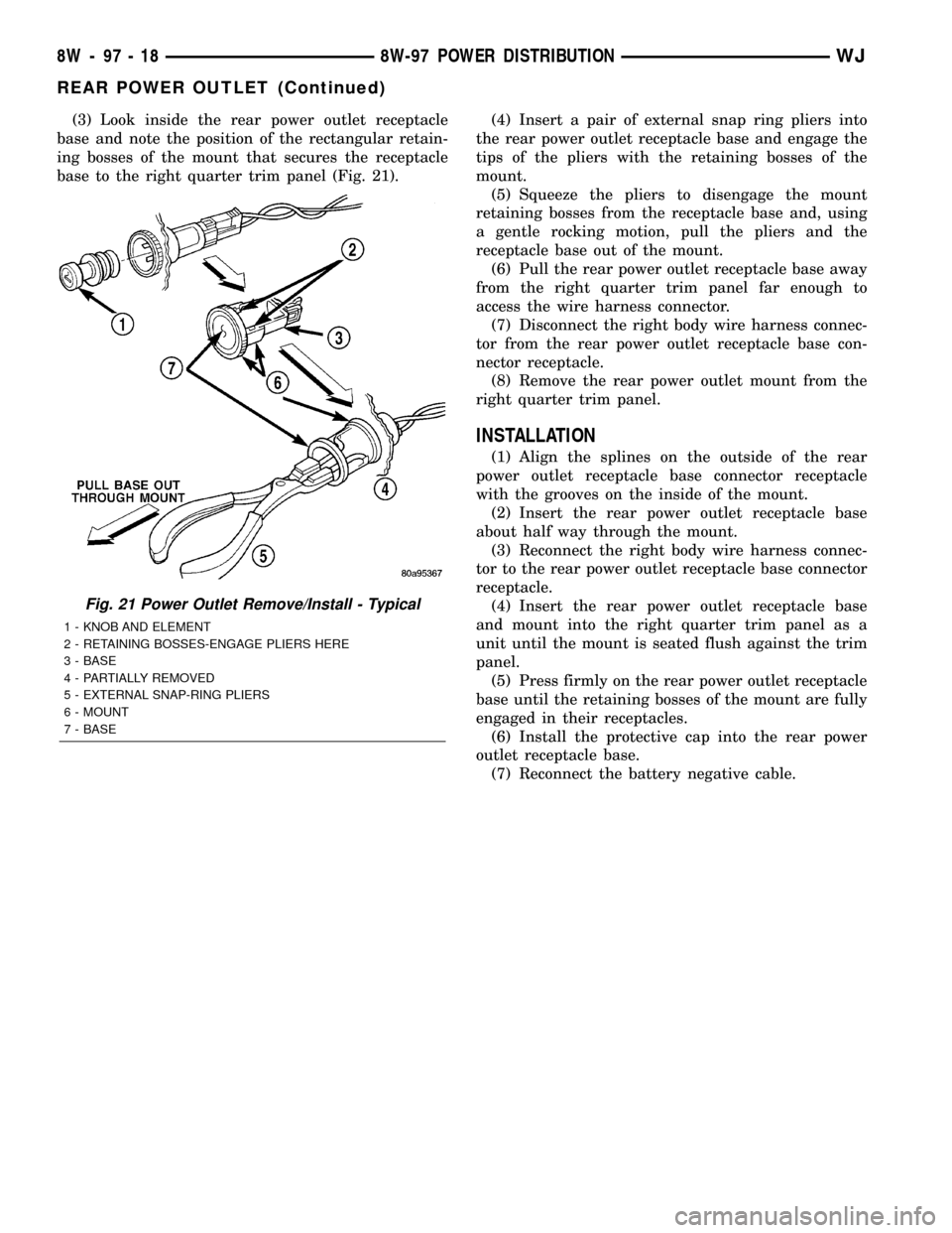
(3) Look inside the rear power outlet receptacle
base and note the position of the rectangular retain-
ing bosses of the mount that secures the receptacle
base to the right quarter trim panel (Fig. 21).(4) Insert a pair of external snap ring pliers into
the rear power outlet receptacle base and engage the
tips of the pliers with the retaining bosses of the
mount.
(5) Squeeze the pliers to disengage the mount
retaining bosses from the receptacle base and, using
a gentle rocking motion, pull the pliers and the
receptacle base out of the mount.
(6) Pull the rear power outlet receptacle base away
from the right quarter trim panel far enough to
access the wire harness connector.
(7) Disconnect the right body wire harness connec-
tor from the rear power outlet receptacle base con-
nector receptacle.
(8) Remove the rear power outlet mount from the
right quarter trim panel.
INSTALLATION
(1) Align the splines on the outside of the rear
power outlet receptacle base connector receptacle
with the grooves on the inside of the mount.
(2) Insert the rear power outlet receptacle base
about half way through the mount.
(3) Reconnect the right body wire harness connec-
tor to the rear power outlet receptacle base connector
receptacle.
(4) Insert the rear power outlet receptacle base
and mount into the right quarter trim panel as a
unit until the mount is seated flush against the trim
panel.
(5) Press firmly on the rear power outlet receptacle
base until the retaining bosses of the mount are fully
engaged in their receptacles.
(6) Install the protective cap into the rear power
outlet receptacle base.
(7) Reconnect the battery negative cable.
Fig. 21 Power Outlet Remove/Install - Typical
1 - KNOB AND ELEMENT
2 - RETAINING BOSSES-ENGAGE PLIERS HERE
3 - BASE
4 - PARTIALLY REMOVED
5 - EXTERNAL SNAP-RING PLIERS
6 - MOUNT
7 - BASE
8W - 97 - 18 8W-97 POWER DISTRIBUTIONWJ
REAR POWER OUTLET (Continued)
Page 1251 of 2199
DIAGNOSIS AND TESTINGÐCYLINDER
COMPRESSION PRESSURE
The results of a cylinder compression pressure test
can be utilized to diagnose several engine malfunc-
tions.
Ensure the battery is completely charged and the
engine starter motor is in good operating condition.
Otherwise, the indicated compression pressures may
not be valid for diagnosis purposes.
(1) Clean the spark plug recesses with compressed
air.
(2) Remove the spark plugs (Refer to 8 - ELEC-
TRICAL/IGNITION CONTROL/SPARK PLUG -
REMOVAL).
(3) Secure the throttle in the wide-open position.
(4) Disconnect the ignition coil.
(5) Insert a compression pressure gauge and rotate
the engine with the engine starter motor for three
revolutions.
(6) Record the compression pressure on the third
revolution. Continue the test for the remaining cylin-
ders.
(Refer to 9 - ENGINE - SPECIFICATIONS) for the
correct engine compression pressures.
DIAGNOSIS AND TESTING - CYLINDER
COMBUSTION PRESSURE LEAKAGE
The combustion pressure leakage test provides an
accurate means for determining engine condition.
Combustion pressure leakage testing will detect:
²Exhaust and intake valve leaks (improper seat-
ing)
²Leaks between adjacent cylinders or into water
jacket²Any causes for combustion/compression pressure
loss
WARNING: DO NOT REMOVE THE RADIATOR CAP
WITH THE SYSTEM HOT AND UNDER PRESSURE.
SERIOUS BURNS FROM HOT COOLANT CAN
OCCUR.
Check the coolant level and fill as required. DO
NOT install the radiator cap.
Start and operate the engine until it attains nor-
mal operating temperature, then turn OFF the
engine.
Remove the spark plugs.
Remove the oil filler cap.
Remove the air cleaner.
Calibrate the tester according to the manufactur-
er's instructions. The shop air source for testing
should maintain 483 kPa (70 psi) minimum, 1,379
kPa (200 psi) maximum and 552 kPa (80 psi) recom-
mended.
Perform the test procedure on each cylinder accord-
ing to the tester manufacturer's instructions. While
testing, listen for pressurized air escaping through
the throttle body, tailpipe or oil filler cap opening.
Check for bubbles in the radiator coolant.
All gauge pressure indications should be equal,
with no more than 25% leakage.
FOR EXAMPLE:At 552 kPa (80 psi) input pres-
sure, a minimum of 414 kPa (60 psi) should be main-
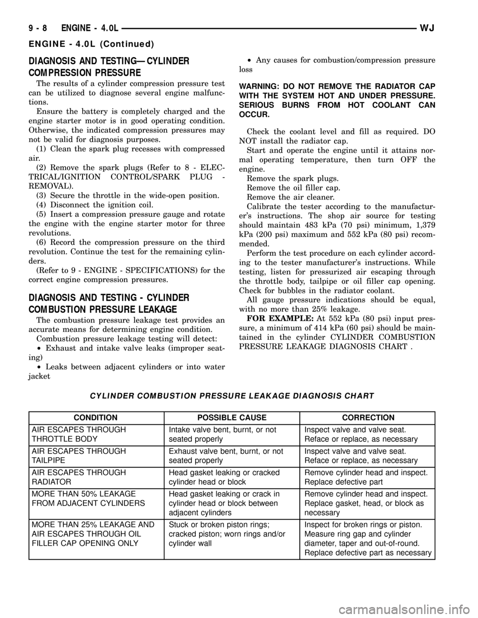
tained in the cylinder CYLINDER COMBUSTION
PRESSURE LEAKAGE DIAGNOSIS CHART .
CYLINDER COMBUSTION PRESSURE LEAKAGE DIAGNOSIS CHART
CONDITION POSSIBLE CAUSE CORRECTION
AIR ESCAPES THROUGH
THROTTLE BODYIntake valve bent, burnt, or not
seated properlyInspect valve and valve seat.
Reface or replace, as necessary
AIR ESCAPES THROUGH
TAILPIPEExhaust valve bent, burnt, or not
seated properlyInspect valve and valve seat.
Reface or replace, as necessary
AIR ESCAPES THROUGH
RADIATORHead gasket leaking or cracked
cylinder head or blockRemove cylinder head and inspect.
Replace defective part
MORE THAN 50% LEAKAGE
FROM ADJACENT CYLINDERSHead gasket leaking or crack in
cylinder head or block between
adjacent cylindersRemove cylinder head and inspect.
Replace gasket, head, or block as
necessary
MORE THAN 25% LEAKAGE AND
AIR ESCAPES THROUGH OIL
FILLER CAP OPENING ONLYStuck or broken piston rings;
cracked piston; worn rings and/or
cylinder wallInspect for broken rings or piston.
Measure ring gap and cylinder
diameter, taper and out-of-round.
Replace defective part as necessary
9 - 8 ENGINE - 4.0LWJ
ENGINE - 4.0L (Continued)
Page 1253 of 2199

FORM-IN-PLACE GASKET AND SEALER
APPLICATION
Assembling parts using a form-in-place gasket
requires care but it's easier then using precut gaskets.
MopartGasket Maker material should be applied
sparingly 1 mm (0.040 in.) diameter or less of sealant
to one gasket surface. Be certain the material sur-
rounds each mounting hole. Excess material can eas-
ily be wiped off. Components should be torqued in
place within 15 minutes. The use of a locating dowel
is recommended during assembly to prevent smear-
ing material off the location.
MopartEngine RTV GEN II or ATF RTV gasket
material should be applied in a continuous bead
approximately 3 mm (0.120 in.) in diameter. All
mounting holes must be circled. For corner sealing, a
3.17 or 6.35 mm (1/8 or 1/4 in.) drop is placed in the
center of the gasket contact area. Uncured sealant
may be removed with a shop towel. Components
should be torqued in place while the sealant is still
wet to the touch (within 10 minutes). The usage of a
locating dowel is recommended during assembly to
prevent smearing material off the location.
MopartGasket Sealant in an aerosol can should be
applied using a thin, even coat sprayed completely
over both surfaces to be joined, and both sides of a
gasket. Then proceed with assembly. Material in a
can w/applicator can be brushed on evenly over the
sealing surfaces. Material in an aerosol can should be
used on engines with multi-layer steel gaskets.
STANDARD PROCEDURE - REPAIR DAMAGED
OR WORN THREADS
CAUTION: Be sure that the tapped holes maintain
the original center line.
Damaged or worn threads can be repaired. Essen-
tially, this repair consists of:
²Drilling out worn or damaged threads.
²Tapping the hole with a special Heli-Coil Tap, or
equivalent.
²Installing an insert into the tapped hole to bring
the hole back to its original thread size.
STANDARD PROCEDUREÐHYDROSTATIC LOCK
CAUTION: DO NOT use the starter motor to rotate
the crankshaft. Severe damage could occur.
When an engine is suspected of hydrostatic lock
(regardless of what caused the problem), follow the
steps below.
(1) Perform the Fuel Pressure Release Procedure
(Refer to 14 - FUEL SYSTEM/FUEL DELIVERY -
STANDARD PROCEDURE).(2) Disconnect the negative cable(s) from the bat-
tery.
(3) Inspect air cleaner, induction system, and
intake manifold to ensure system is dry and clear of
foreign material.
(4) Place a shop towel around the spark plugs to
catch any fluid that may possibly be under pressure
in the cylinder head. Remove the spark plugs.
(5) With all spark plugs removed, rotate the crank-
shaft using a breaker bar and socket.
(6) Identify the fluid in the cylinders (coolant, fuel,
oil, etc.).
(7) Be sure all fluid has been removed from the
cylinders.
(8) Repair engine or components as necessary to
prevent this problem from occurring again.
(9) Squirt a small amount of engine oil into the
cylinders to lubricate the walls. This will prevent
damage on restart.
(10) Install new spark plugs. Tighten the spark
plugs to 41 N´m (30 ft. lbs.) torque.
(11) Drain engine oil. Remove and discard the oil
filter.
(12) Install the drain plug. Tighten the plug to 34
N´m (25 ft. lbs.) torque.
(13) Install a new oil filter.
(14) Fill engine crankcase with the specified
amount and grade of oil. (Refer to LUBRICATION &
MAINTENANCE - SPECIFICATIONS).
(15) Connect the negative cable(s) to the battery.
(16) Start the engine and check for any leaks.
STANDARD PROCEDURE - CYLINDER BORE
HONING
Before honing, stuff plenty of clean shop towels
under the bores and over the crankshaft to keep
abrasive materials from entering the crankshaft
area.
(1)
Used carefully, the Cylinder Bore Sizing Hone
C-823, equipped with 220 grit stones, is the best tool
for this job. In addition to deglazing, it will reduce
taper and out-of-round, as well as removing light scuff-
ing, scoring and scratches. Usually, a few strokes will
clean up a bore and maintain the required limits.
CAUTION: DO NOT use rigid type hones to remove
cylinder wall glaze.
(2) Deglazing of the cylinder walls may be done if
the cylinder bore is straight and round. Use a cylin-
der surfacing hone, Honing Tool C-3501, equipped
with 280 grit stones (C-3501-3810). about 20-60
strokes, depending on the bore condition, will be suf-
ficient to provide a satisfactory surface. Using honing
oil C-3501-3880, or a light honing oil, available from
major oil distributors.
9 - 10 ENGINE - 4.0LWJ
ENGINE - 4.0L (Continued)
Page 1255 of 2199

(7) Remove the fan assembly from the water pump
(Refer to 7 - COOLING/ENGINE/RADIATOR FAN -
REMOVAL).
(8) Remove the fan shroud.
(9) Disconnect the transmission fluid cooler lines
(automatic transmission).
(10) Discharge the A/C system (Refer to 24 -
HEATING & AIR CONDITIONING/PLUMBING -
STANDARD PROCEDURE).
(11) Remove the service valves and cap the com-
pressor ports.
(12) Remove the radiator or radiator/condenser (if
equipped with A/C).
(13) Disconnect the heater hoses at the engine
thermostat housing and water pump.
(14) Disconnect the accelerator cable, transmission
line pressure cable and speed control cable (if
equipped) from the throttle body.
(15) Remove cables from the bracket and secure
out of the way.
(16) Disconnect the body ground at the engine.
(17) Disconnect the following connectors and
secure their harness out of the way.
²Power steering pressure switch
²Coolant temperature sensor
²Six (6) fuel injector connectors
²Intake air temperature sensor
²Throttle position sensor
²Map sensor
²Crankshaft position sensor
²Oxygen sensor
²Camshaft position sensor
²Generator connector and B+ terminal wire
(18) Disconnect the coil rail electrical connections
and the oil pressure switch connector.
(19) Perform the fuel pressure release procedure
(Refer to 14 - FUEL SYSTEM/FUEL DELIVERY -
STANDARD PROCEDURE).
(20) Disconnect the fuel supply line at the injector
rail (Refer to 14 - FUEL SYSTEM/FUEL DELIVERY/
QUICK CONNECT FITTING - STANDARD PROCE-
DURE).
(21) Remove the fuel line bracket from the intake
manifold.
(22) Remove the air cleaner assembly (Fig. 5).
(23) Disconnect the hoses from the fittings at the
steering gear.
(24) Drain the pump reservoir.
(25) Cap the fittings on the hoses and steering
gear to prevent foreign objects from entering the sys-
tem.
(26) Raise and support the vehicle.
(27) Disconnect the wires from the engine starter
motor solenoid.(28) Remove the engine starter motor (Refer to 8 -
ELECTRICAL/STARTING/STARTER MOTOR -
REMOVAL).
(29) Disconnect the oxygen sensor from the
exhaust pipe.
(30) Disconnect the exhaust pipe from the mani-
fold.
(31) Remove the exhaust pipe support.
(32) Remove the bending brace (Refer to 9 -
ENGINE/ENGINE BLOCK/STRUCT SUPPORT -
REMOVAL).
(33) Remove the engine flywheel/converter housing
access cover.
(34) Mark the converter and drive plate location.
(35) Remove the converter-to-drive plate bolts.
(36) Remove the upper engine flywheel/converter
housing bolts and loosen the bottom bolts.
(37) Remove the engine mount cushion-to-engine
compartment bracket bolts.
(38) Lower the vehicle.
(39) Attach a lifting device to the engine.
(40) Raise the engine off the front supports.
(41) Place a support or floor jack under the con-
verter (or engine flywheel) housing.
(42) Remove the remaining converter (or engine
flywheel) housing bolts.
(43) Lift the engine out of the engine compart-
ment.
Fig. 5 Air Cleaner Assembly
1 - POWER STEERING PUMP
2 - AIR CLEANER ASSEMBLY
9 - 12 ENGINE - 4.0LWJ
ENGINE - 4.0L (Continued)
Page 1262 of 2199
(2) Lift cover up and position to the side.
(3) Remove air cleaner element.
INSTALLATION - 4.0L
(1) Clean inside of air cleaner housing before
installing new element.
(2) Install air cleaner element into housing.
(3) Latch clips and clamp cover down to secure. Be
sure air cleaner cover is properly seated to air
cleaner housing.
AIR CLEANER HOUSING
REMOVAL - 4.0L
(1) Disconnect air cleaner cover-to-air duct clamp
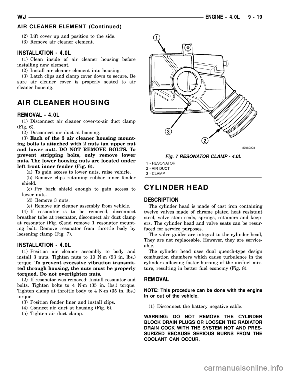
(Fig. 6).
(2) Disconnect air duct at housing.
(3)Each of the 3 air cleaner housing mount-
ing bolts is attached with 2 nuts (an upper nut
and lower nut). DO NOT REMOVE BOLTS. To
prevent stripping bolts, only remove lower
nuts. The lower housing nuts are located under
left front inner fender (Fig. 6).
(a) To gain access to lower nuts, raise vehicle.
(b) Remove clips retaining rubber inner fender
shield.
(c) Pry back shield enough to gain access to
lower nuts.
(d) Remove 3 nuts.
(e) Remove air cleaner assembly from vehicle.
(4) If resonator is to be removed, disconnect
breather tube at resonator, disconnect air duct clamp
at resonator (Fig. 6)and remove 1 resonator mount-
ing bolt. Remove resonator from throttle body by
loosening clamp (Fig. 7).
INSTALLATION - 4.0L
(1) Position air cleaner assembly to body and
install 3 nuts. Tighten nuts to 10 N´m (93 in. lbs.)
torque.To prevent excessive vibration transmit-
ted through housing, the nuts must be properly
torqued. Do not overtighten nuts.
(2) If resonator was removed: Install resonator and
bolts. Tighten bolts to 4 N´m (35 in. lbs.) torque.
Tighten clamp at throttle body to 4 N´m (35 in. lbs.)
torque.
(3) Position fender liner and install clips.
(4) Connect air duct at housing (Fig. 6).
(5) Tighten air duct clamp.
CYLINDER HEAD
DESCRIPTION
The cylinder head is made of cast iron containing
twelve valves made of chrome plated heat resistant
steel, valve stem seals, springs, retainers and keep-
ers. The cylinder head and valve seats can be resur-
faced for service purposes.
The valve guides are integral to the cylinder head,
They are not replaceable. However, they are service-
able.
The cylinder head uses dual quench-type design
combustion chambers which cause turbulence in the
cylinders allowing faster burning of the air/fuel mix-
ture, resulting in better fuel economy (Fig. 8).
REMOVAL
NOTE: This procedure can be done with the engine
in or out of the vehicle.
(1) Disconnect the battery negative cable.
WARNING: DO NOT REMOVE THE CYLINDER
BLOCK DRAIN PLUGS OR LOOSEN THE RADIATOR
DRAIN COCK WITH THE SYSTEM HOT AND PRES-
SURIZED BECAUSE SERIOUS BURNS FROM THE
COOLANT CAN OCCUR.
Fig. 7 RESONATOR CLAMP - 4.0L
1 - RESONATOR
2 - AIR DUCT
3 - CLAMP
WJENGINE - 4.0L 9 - 19
AIR CLEANER ELEMENT (Continued)