Headliner JEEP GRAND CHEROKEE 2003 WJ / 2.G Owner's Manual
[x] Cancel search | Manufacturer: JEEP, Model Year: 2003, Model line: GRAND CHEROKEE, Model: JEEP GRAND CHEROKEE 2003 WJ / 2.GPages: 2199, PDF Size: 76.01 MB
Page 646 of 2199
along the left roof side rail to the rear of the vehicle.
At the rear of the vehicle, the headliner hose is
routed above the headliner and along the upper lift-
gate opening panel toward the right side of the vehi-
cle. The headliner hose then passes through a hole
with a rubber grommet in the upper liftgate opening
panel and through another hole with a rubber grom-
met into the upper inner liftgate panel to the rear
washer nozzle.
Washer hose is available for service only as roll
stock, which must then be cut to length. The head-
liner washer hose is integral to the headliner unit
and, if faulty or damaged, the headliner unit must be
replaced. The molded plastic washer hose fittings
cannot be repaired. If these fittings are faulty or
damaged, they must be replaced.
OPERATION
Washer fluid in the washer reservoir is pressurized
and fed by the rear washer pump/motor through the
rear washer system plumbing and fittings to the rear
washer nozzle on the liftgate outer panel above the
liftgate glass. Whenever routing the washer hose or a
wire harness containing a washer hose, it must be
routed away from hot, sharp, or moving parts; and,
sharp bends that might pinch the hose must be
avoided.
REAR WASHER NOZZLE
DESCRIPTION
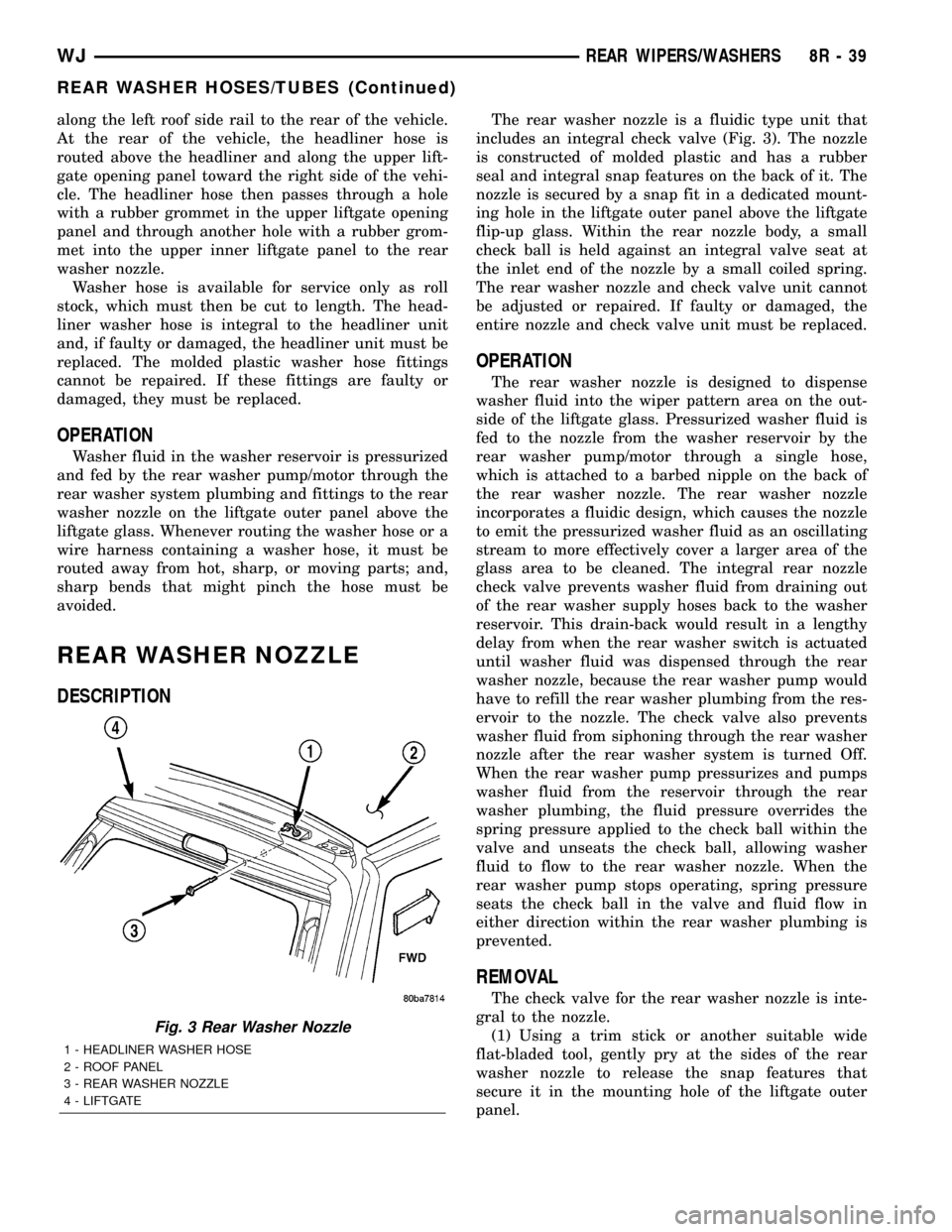
The rear washer nozzle is a fluidic type unit that
includes an integral check valve (Fig. 3). The nozzle
is constructed of molded plastic and has a rubber
seal and integral snap features on the back of it. The
nozzle is secured by a snap fit in a dedicated mount-
ing hole in the liftgate outer panel above the liftgate
flip-up glass. Within the rear nozzle body, a small
check ball is held against an integral valve seat at
the inlet end of the nozzle by a small coiled spring.
The rear washer nozzle and check valve unit cannot
be adjusted or repaired. If faulty or damaged, the
entire nozzle and check valve unit must be replaced.
OPERATION
The rear washer nozzle is designed to dispense
washer fluid into the wiper pattern area on the out-
side of the liftgate glass. Pressurized washer fluid is
fed to the nozzle from the washer reservoir by the
rear washer pump/motor through a single hose,
which is attached to a barbed nipple on the back of
the rear washer nozzle. The rear washer nozzle
incorporates a fluidic design, which causes the nozzle
to emit the pressurized washer fluid as an oscillating
stream to more effectively cover a larger area of the
glass area to be cleaned. The integral rear nozzle
check valve prevents washer fluid from draining out
of the rear washer supply hoses back to the washer
reservoir. This drain-back would result in a lengthy
delay from when the rear washer switch is actuated
until washer fluid was dispensed through the rear
washer nozzle, because the rear washer pump would
have to refill the rear washer plumbing from the res-
ervoir to the nozzle. The check valve also prevents
washer fluid from siphoning through the rear washer
nozzle after the rear washer system is turned Off.
When the rear washer pump pressurizes and pumps
washer fluid from the reservoir through the rear
washer plumbing, the fluid pressure overrides the
spring pressure applied to the check ball within the
valve and unseats the check ball, allowing washer
fluid to flow to the rear washer nozzle. When the
rear washer pump stops operating, spring pressure
seats the check ball in the valve and fluid flow in
either direction within the rear washer plumbing is
prevented.
REMOVAL
The check valve for the rear washer nozzle is inte-
gral to the nozzle.
(1) Using a trim stick or another suitable wide
flat-bladed tool, gently pry at the sides of the rear
washer nozzle to release the snap features that
secure it in the mounting hole of the liftgate outer
panel.
Fig. 3 Rear Washer Nozzle
1 - HEADLINER WASHER HOSE
2 - ROOF PANEL
3 - REAR WASHER NOZZLE
4 - LIFTGATE
WJREAR WIPERS/WASHERS 8R - 39
REAR WASHER HOSES/TUBES (Continued)
Page 647 of 2199
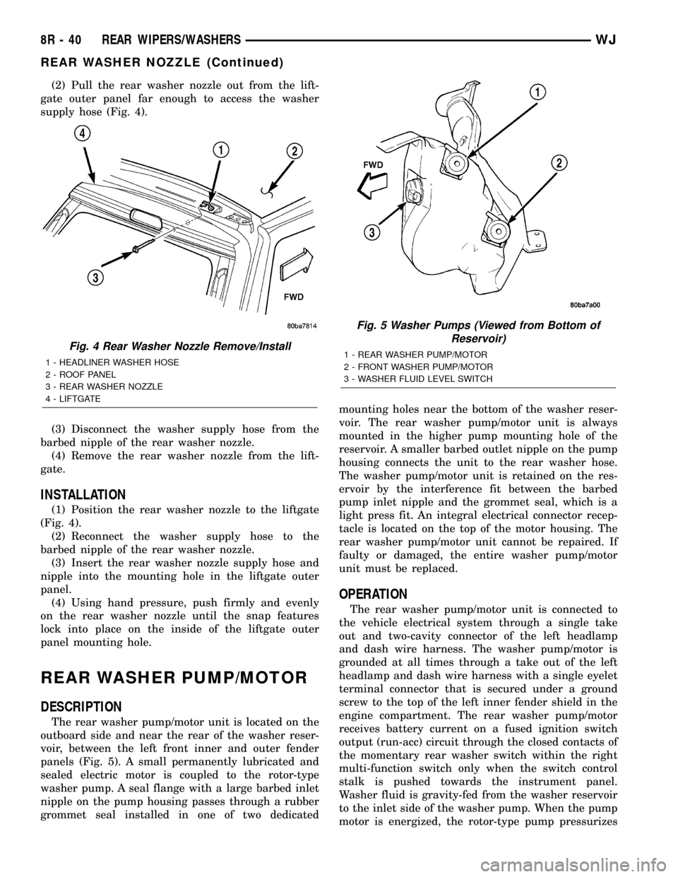
(2) Pull the rear washer nozzle out from the lift-
gate outer panel far enough to access the washer
supply hose (Fig. 4).
(3) Disconnect the washer supply hose from the
barbed nipple of the rear washer nozzle.
(4) Remove the rear washer nozzle from the lift-
gate.
INSTALLATION
(1) Position the rear washer nozzle to the liftgate
(Fig. 4).
(2) Reconnect the washer supply hose to the
barbed nipple of the rear washer nozzle.
(3) Insert the rear washer nozzle supply hose and
nipple into the mounting hole in the liftgate outer
panel.
(4) Using hand pressure, push firmly and evenly
on the rear washer nozzle until the snap features
lock into place on the inside of the liftgate outer
panel mounting hole.
REAR WASHER PUMP/MOTOR
DESCRIPTION
The rear washer pump/motor unit is located on the
outboard side and near the rear of the washer reser-
voir, between the left front inner and outer fender
panels (Fig. 5). A small permanently lubricated and
sealed electric motor is coupled to the rotor-type
washer pump. A seal flange with a large barbed inlet
nipple on the pump housing passes through a rubber
grommet seal installed in one of two dedicatedmounting holes near the bottom of the washer reser-
voir. The rear washer pump/motor unit is always
mounted in the higher pump mounting hole of the
reservoir. A smaller barbed outlet nipple on the pump
housing connects the unit to the rear washer hose.
The washer pump/motor unit is retained on the res-
ervoir by the interference fit between the barbed
pump inlet nipple and the grommet seal, which is a
light press fit. An integral electrical connector recep-
tacle is located on the top of the motor housing. The
rear washer pump/motor unit cannot be repaired. If
faulty or damaged, the entire washer pump/motor
unit must be replaced.
OPERATION
The rear washer pump/motor unit is connected to
the vehicle electrical system through a single take
out and two-cavity connector of the left headlamp
and dash wire harness. The washer pump/motor is
grounded at all times through a take out of the left
headlamp and dash wire harness with a single eyelet
terminal connector that is secured under a ground
screw to the top of the left inner fender shield in the
engine compartment. The rear washer pump/motor
receives battery current on a fused ignition switch
output (run-acc) circuit through the closed contacts of
the momentary rear washer switch within the right
multi-function switch only when the switch control
stalk is pushed towards the instrument panel.
Washer fluid is gravity-fed from the washer reservoir
to the inlet side of the washer pump. When the pump
motor is energized, the rotor-type pump pressurizes
Fig. 4 Rear Washer Nozzle Remove/Install
1 - HEADLINER WASHER HOSE
2 - ROOF PANEL
3 - REAR WASHER NOZZLE
4 - LIFTGATE
Fig. 5 Washer Pumps (Viewed from Bottom of
Reservoir)
1 - REAR WASHER PUMP/MOTOR
2 - FRONT WASHER PUMP/MOTOR
3 - WASHER FLUID LEVEL SWITCH
8R - 40 REAR WIPERS/WASHERSWJ
REAR WASHER NOZZLE (Continued)
Page 1178 of 2199
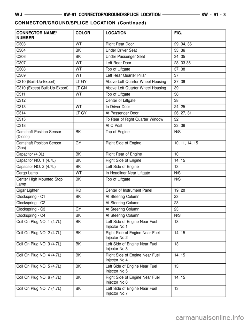
CONNECTOR NAME/
NUMBERCOLOR LOCATION FIG.
C303 WT Right Rear Door 29, 34, 36
C304 BK Under Driver Seat 33, 36
C306 BK Under Passenger Seat 34, 35
C307 WT Left Rear Door 28, 33 35
C308 WT Top of Liftgate 37, 38
C309 WT Left Rear Quarter Pillar 37
C310 (Built-Up-Export) LT GY Above Left Quarter Wheel Housing 37, 39
C310 (Except Built-Up-Export) LT GN Above Left Quarter Wheel Housing 39
C311 WT Top of Liftgate 38
C312 Center of Liftgate 38
C313 WT In Driver Door 24, 25
C314 LT GY At Passenger Door 26, 27, 31
C315 To Rear of Right Quarter Window 32
C318 At C Post 33, 36
Camshaft Position Sensor
(Diesel)BK Top of Engine N/S
Camshaft Position Sensor
(Gas)GY Right Side of Engine 10, 11, 14, 15
Capacitor (4.0L) BK Right Rear of Engine 10
Capacitor NO. 1 (4.7L) BK Right Side of Engine 14, 15
Capacitor NO. 2 (4.7L) BK Left Side of Engine 13
Cargo Lamp WT In Headliner Near Liftgate N/S
Center High Mounted Stop
LampBK Top of Liftgate N/S
Cigar Lighter RD Center of Instrument Panel 19, 20
Clockspring - C1 BK At Steering Column 23
Clockspring - C2 At Steering Column 23
Clockspring - C3 GY At Steering Column 23
Clockspring - C4 BK At Steering Column N/S
Coil On Plug NO. 1 (4.7L) BK Left Side of Engine Near Fuel
Injector No.113
Coil On Plug NO. 2 (4.7L) BK Right Side of Engine Near Fuel
Injector No.214, 15
Coil On Plug NO. 3 (4.7L) BK Left Side of Engine Near Fuel
Injector No.313
Coil On Plug NO. 4 (4.7L) BK Right Side of Engine Near Fuel
Injector No.414, 15
Coil On Plug NO. 5 (4.7L) BK Left Side of Engine Near Fuel
Injector No.513
Coil On Plug NO. 6 (4.7L) BK Right Side of Engine Near Fuel
Injector No.614, 15
Coil On Plug NO. 7 (4.7L) BK Left Side of Engine Near Fuel
Injector No.713
WJ8W-91 CONNECTOR/GROUND/SPLICE LOCATION 8W - 91 - 3
CONNECTOR/GROUND/SPLICE LOCATION (Continued)
Page 1942 of 2199
INTERIOR
TABLE OF CONTENTS
page page
A-PILLAR TRIM
REMOVAL.............................69
INSTALLATION.........................69
ASSIST HANDLE
REMOVAL.............................70
INSTALLATION.........................70
B-PILLAR LOWER TRIM
REMOVAL.............................70
INSTALLATION.........................70
B-PILLAR UPPER TRIM
REMOVAL.............................71
INSTALLATION.........................71
CARPETS AND FLOOR MATS
REMOVAL
REMOVAL - FRONT CARPET............71
REMOVAL - CARGO AREA CARPET.......71
INSTALLATION
INSTALLATION - FRONT CARPET.........71
INSTALLATION - CARGO AREA CARPET . . . 72
COWL TRIM
REMOVAL.............................72
INSTALLATION.........................72
C-PILLAR TRIM
REMOVAL.............................72
INSTALLATION.........................72
DOOR SILL SCUFF PLATE
REMOVAL.............................74
INSTALLATION.........................74
DOOR SILL TRIM
REMOVAL.............................74INSTALLATION.........................74
D-PILLAR TRIM
REMOVAL.............................75
INSTALLATION.........................75
FLOOR CONSOLE
REMOVAL.............................76
INSTALLATION.........................76
HEADLINER
REMOVAL.............................77
INSTALLATION.........................77
LIFTGATE OPENING UPPER TRIM
REMOVAL.............................79
INSTALLATION.........................79
QUARTER TRIM PANEL
REMOVAL.............................79
INSTALLATION.........................79
REAR STORAGE BOX
REMOVAL.............................79
INSTALLATION.........................80
REAR VIEW MIRROR
REMOVAL.............................80
INSTALLATION
INSTALLATION.......................80
INSTALLATION - REARVIEW MIRROR
SUPPORT BRACKET...................80
SUN VISOR
REMOVAL.............................80
INSTALLATION.........................80
A-PILLAR TRIM
REMOVAL
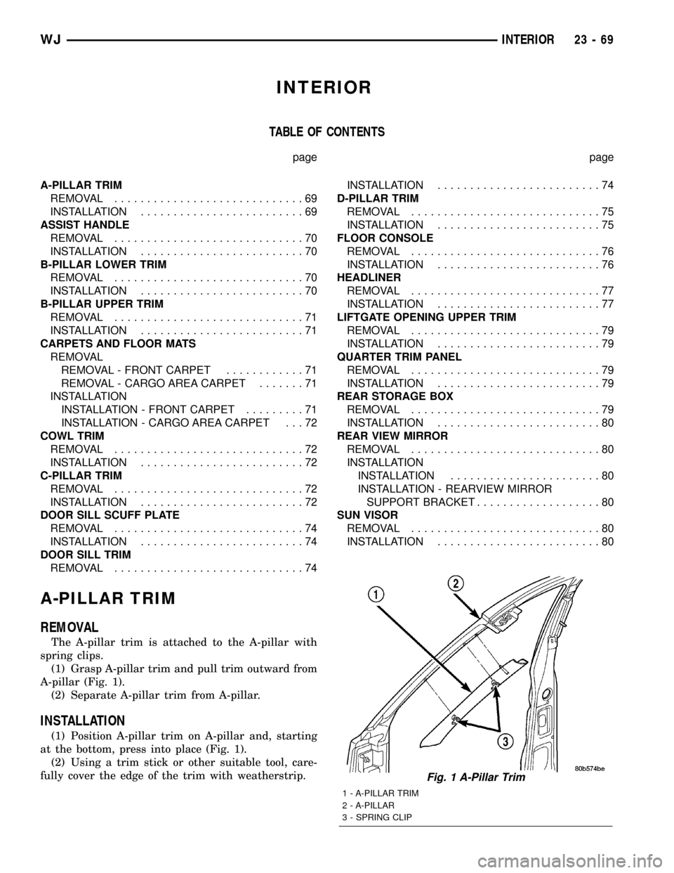
The A-pillar trim is attached to the A-pillar with
spring clips.
(1) Grasp A-pillar trim and pull trim outward from
A-pillar (Fig. 1).
(2) Separate A-pillar trim from A-pillar.
INSTALLATION
(1) Position A-pillar trim on A-pillar and, starting
at the bottom, press into place (Fig. 1).
(2) Using a trim stick or other suitable tool, care-
fully cover the edge of the trim with weatherstrip.
Fig. 1 A-Pillar Trim
1 - A-PILLAR TRIM
2 - A-PILLAR
3 - SPRING CLIP
WJINTERIOR 23 - 69
Page 1950 of 2199
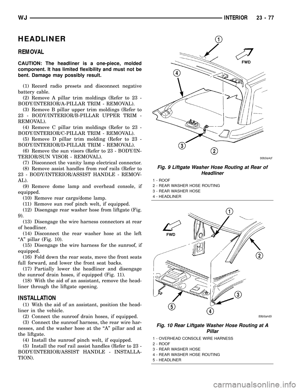
HEADLINER
REMOVAL
CAUTION: The headliner is a one-piece, molded
component. It has limited flexibility and must not be
bent. Damage may possibly result.
(1) Record radio presets and disconnect negative
battery cable.
(2) Remove A pillar trim moldings (Refer to 23 -
BODY/INTERIOR/A-PILLAR TRIM - REMOVAL).
(3) Remove B pillar upper trim moldings (Refer to
23 - BODY/INTERIOR/B-PILLAR UPPER TRIM -
REMOVAL).
(4) Remove C pillar trim moldings (Refer to 23 -
BODY/INTERIOR/C-PILLAR TRIM - REMOVAL).
(5) Remove D pillar trim molding (Refer to 23 -
BODY/INTERIOR/D-PILLAR TRIM - REMOVAL).
(6) Remove the sun visors (Refer to 23 - BODY/IN-
TERIOR/SUN VISOR - REMOVAL).
(7) Disconnect the vanity lamp electrical connector.
(8) Remove assist handles from roof rails (Refer to
23 - BODY/INTERIOR/ASSIST HANDLE - REMOV-
AL).
(9) Remove dome lamp and overhead console, if
equipped.
(10) Remove rear cargo/dome lamp.
(11) Remove sun roof pinch welt, if equipped.
(12) Disengage rear washer hose from liftgate (Fig.
9).
(13) Disengage the wire harness connectors at rear
of headliner.
(14) Disconnect the rear washer hose at the left
ªAº pillar (Fig. 10).
(15) Disengage the wire harness for the sunroof, if
equipped.
(16) Fold down the rear seats, move the front seats
full forward, and lower the front seat backs.
(17) Partially lower the headliner and disengage
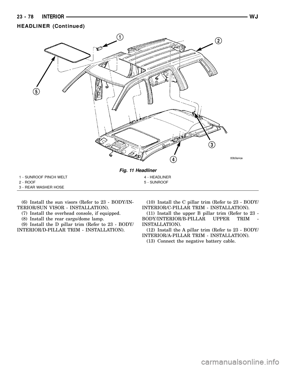
the sunroof drain hoses, if equipped (Fig. 11).
(18) With the aid of an assistant, remove the head-
liner through the liftgate opening.
INSTALLATION
(1) With the aid of an assistant, position the head-
liner in the vehicle.
(2) Connect the sunroof drain hoses, if equipped.
(3) Connect the sunroof harness, the rear wire har-
nesses, and the washer hose at the ªAº pillar and at
the liftgate.
(4) Install the sunroof pinch welt, if equipped.
(5) Install the roof rail assist handles (Refer to 23 -
BODY/INTERIOR/ASSIST HANDLE - INSTALLA-
TION).
Fig. 9 Liftgate Washer Hose Routing at Rear of
Headliner
1 - ROOF
2 - REAR WASHER HOSE ROUTING
3 - REAR WASHER HOSE
4 - HEADLINER
Fig. 10 Rear Liftgate Washer Hose Routing at A
Pillar
1 - OVERHEAD CONSOLE WIRE HARNESS
2 - ROOF
3 - REAR WASHER HOSE
4 - REAR WASHER HOSE ROUTING
5 - HEADLINER
WJINTERIOR 23 - 77
Page 1951 of 2199
(6) Install the sun visors (Refer to 23 - BODY/IN-
TERIOR/SUN VISOR - INSTALLATION).
(7) Install the overhead console, if equipped.
(8) Install the rear cargo/dome lamp.
(9) Install the D pillar trim (Refer to 23 - BODY/
INTERIOR/D-PILLAR TRIM - INSTALLATION).(10) Install the C pillar trim (Refer to 23 - BODY/
INTERIOR/C-PILLAR TRIM - INSTALLATION).
(11) Install the upper B pillar trim (Refer to 23 -
BODY/INTERIOR/B-PILLAR UPPER TRIM -
INSTALLATION).
(12) Install the A pillar trim (Refer to 23 - BODY/
INTERIOR/A-PILLAR TRIM - INSTALLATION).
(13) Connect the negative battery cable.
Fig. 11 Headliner
1 - SUNROOF PINCH WELT
2 - ROOF
3 - REAR WASHER HOSE4 - HEADLINER
5 - SUNROOF
23 - 78 INTERIORWJ
HEADLINER (Continued)
Page 1952 of 2199
LIFTGATE OPENING UPPER
TRIM
REMOVAL
The upper liftgate opening trim is held on with
spring clips.
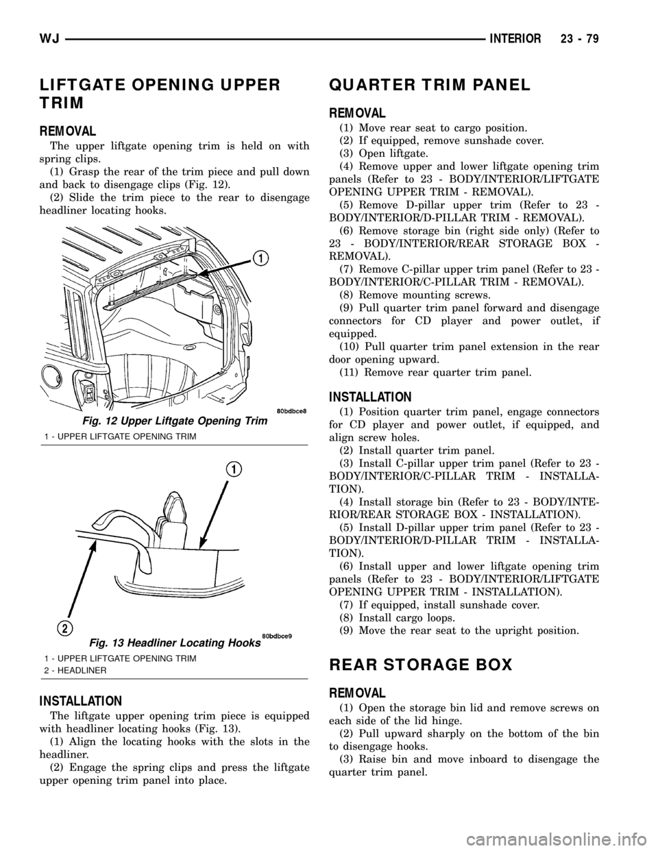
(1) Grasp the rear of the trim piece and pull down
and back to disengage clips (Fig. 12).
(2) Slide the trim piece to the rear to disengage
headliner locating hooks.
INSTALLATION
The liftgate upper opening trim piece is equipped
with headliner locating hooks (Fig. 13).
(1) Align the locating hooks with the slots in the
headliner.
(2) Engage the spring clips and press the liftgate
upper opening trim panel into place.
QUARTER TRIM PANEL
REMOVAL
(1) Move rear seat to cargo position.
(2) If equipped, remove sunshade cover.
(3) Open liftgate.
(4) Remove upper and lower liftgate opening trim
panels (Refer to 23 - BODY/INTERIOR/LIFTGATE
OPENING UPPER TRIM - REMOVAL).
(5) Remove D-pillar upper trim (Refer to 23 -
BODY/INTERIOR/D-PILLAR TRIM - REMOVAL).
(6) Remove storage bin (right side only) (Refer to
23 - BODY/INTERIOR/REAR STORAGE BOX -
REMOVAL).
(7) Remove C-pillar upper trim panel (Refer to 23 -
BODY/INTERIOR/C-PILLAR TRIM - REMOVAL).
(8) Remove mounting screws.
(9) Pull quarter trim panel forward and disengage
connectors for CD player and power outlet, if
equipped.
(10) Pull quarter trim panel extension in the rear
door opening upward.
(11) Remove rear quarter trim panel.
INSTALLATION
(1) Position quarter trim panel, engage connectors
for CD player and power outlet, if equipped, and
align screw holes.
(2) Install quarter trim panel.
(3) Install C-pillar upper trim panel (Refer to 23 -
BODY/INTERIOR/C-PILLAR TRIM - INSTALLA-
TION).
(4) Install storage bin (Refer to 23 - BODY/INTE-
RIOR/REAR STORAGE BOX - INSTALLATION).
(5) Install D-pillar upper trim panel (Refer to 23 -
BODY/INTERIOR/D-PILLAR TRIM - INSTALLA-
TION).
(6) Install upper and lower liftgate opening trim
panels (Refer to 23 - BODY/INTERIOR/LIFTGATE
OPENING UPPER TRIM - INSTALLATION).
(7) If equipped, install sunshade cover.
(8) Install cargo loops.
(9) Move the rear seat to the upright position.
REAR STORAGE BOX
REMOVAL
(1) Open the storage bin lid and remove screws on
each side of the lid hinge.
(2) Pull upward sharply on the bottom of the bin
to disengage hooks.
(3) Raise bin and move inboard to disengage the
quarter trim panel.
Fig. 12 Upper Liftgate Opening Trim
1 - UPPER LIFTGATE OPENING TRIM
Fig. 13 Headliner Locating Hooks
1 - UPPER LIFTGATE OPENING TRIM
2 - HEADLINER
WJINTERIOR 23 - 79
Page 1953 of 2199
INSTALLATION
(1) Position the bin hooks high in the slots on the
quarter trim panel.
(2) Push downward until the bin snaps into place.
(3) Install the hinge screws.
REAR VIEW MIRROR
REMOVAL
(1)If equipped, disconnect mirror harness connector.
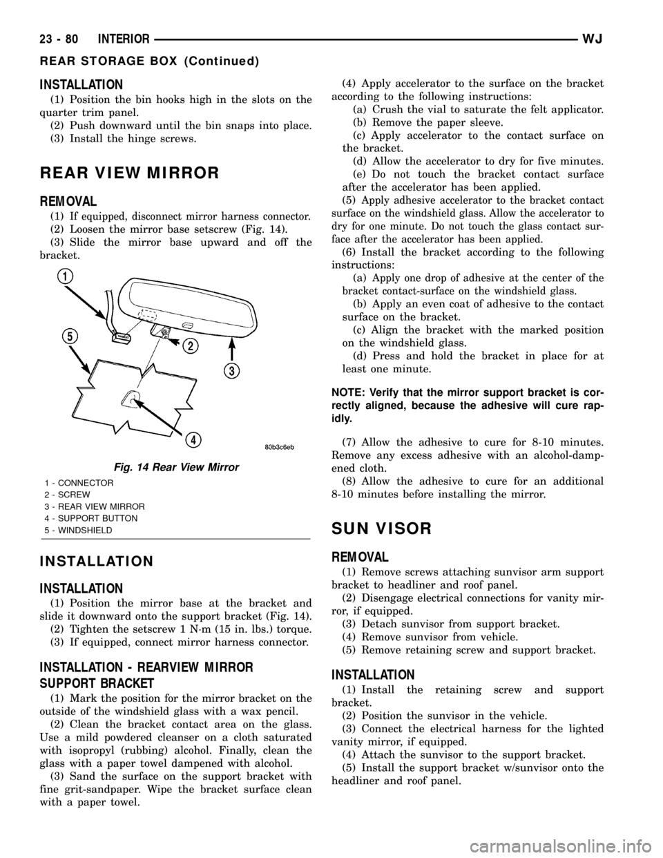
(2) Loosen the mirror base setscrew (Fig. 14).
(3) Slide the mirror base upward and off the
bracket.
INSTALLATION
INSTALLATION
(1) Position the mirror base at the bracket and
slide it downward onto the support bracket (Fig. 14).
(2) Tighten the setscrew 1 N´m (15 in. lbs.) torque.
(3) If equipped, connect mirror harness connector.
INSTALLATION - REARVIEW MIRROR
SUPPORT BRACKET
(1) Mark the position for the mirror bracket on the
outside of the windshield glass with a wax pencil.
(2) Clean the bracket contact area on the glass.
Use a mild powdered cleanser on a cloth saturated
with isopropyl (rubbing) alcohol. Finally, clean the
glass with a paper towel dampened with alcohol.
(3) Sand the surface on the support bracket with
fine grit-sandpaper. Wipe the bracket surface clean
with a paper towel.(4) Apply accelerator to the surface on the bracket
according to the following instructions:
(a) Crush the vial to saturate the felt applicator.
(b) Remove the paper sleeve.
(c) Apply accelerator to the contact surface on
the bracket.
(d) Allow the accelerator to dry for five minutes.
(e) Do not touch the bracket contact surface
after the accelerator has been applied.
(5)
Apply adhesive accelerator to the bracket contact
surface on the windshield glass. Allow the accelerator to
dry for one minute. Do not touch the glass contact sur-
face after the accelerator has been applied.
(6) Install the bracket according to the following
instructions:
(a)
Apply one drop of adhesive at the center of the
bracket contact-surface on the windshield glass.
(b) Apply an even coat of adhesive to the contact
surface on the bracket.
(c) Align the bracket with the marked position
on the windshield glass.
(d) Press and hold the bracket in place for at
least one minute.
NOTE: Verify that the mirror support bracket is cor-
rectly aligned, because the adhesive will cure rap-
idly.
(7) Allow the adhesive to cure for 8-10 minutes.
Remove any excess adhesive with an alcohol-damp-
ened cloth.
(8) Allow the adhesive to cure for an additional
8-10 minutes before installing the mirror.
SUN VISOR
REMOVAL
(1) Remove screws attaching sunvisor arm support
bracket to headliner and roof panel.
(2) Disengage electrical connections for vanity mir-
ror, if equipped.
(3) Detach sunvisor from support bracket.
(4) Remove sunvisor from vehicle.
(5) Remove retaining screw and support bracket.
INSTALLATION
(1) Install the retaining screw and support
bracket.
(2) Position the sunvisor in the vehicle.
(3) Connect the electrical harness for the lighted
vanity mirror, if equipped.
(4) Attach the sunvisor to the support bracket.
(5) Install the support bracket w/sunvisor onto the
headliner and roof panel.
Fig. 14 Rear View Mirror
1 - CONNECTOR
2 - SCREW
3 - REAR VIEW MIRROR
4 - SUPPORT BUTTON
5 - WINDSHIELD
23 - 80 INTERIORWJ
REAR STORAGE BOX (Continued)
Page 1973 of 2199
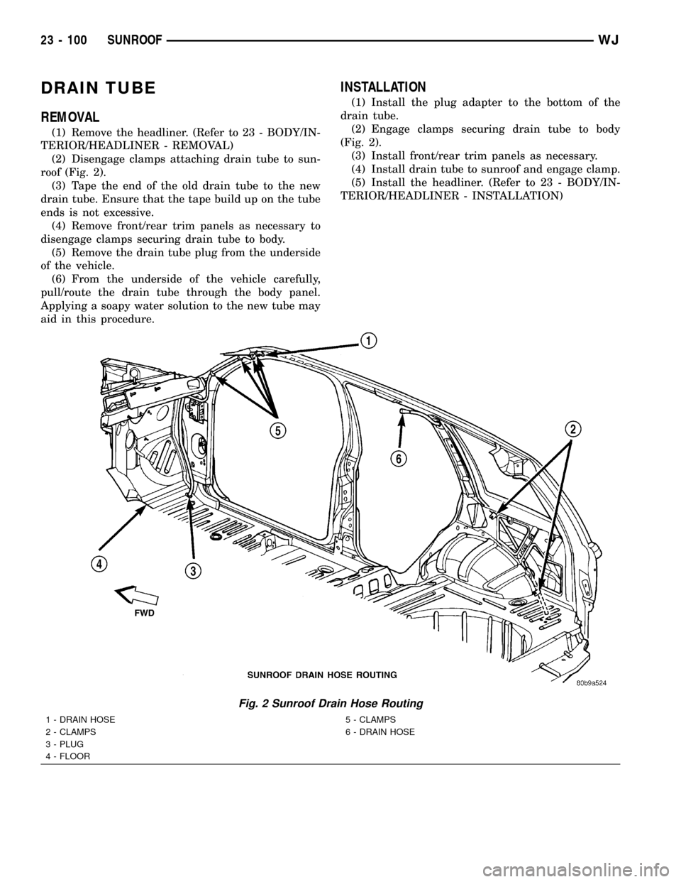
DRAIN TUBE
REMOVAL
(1) Remove the headliner. (Refer to 23 - BODY/IN-
TERIOR/HEADLINER - REMOVAL)
(2) Disengage clamps attaching drain tube to sun-
roof (Fig. 2).
(3) Tape the end of the old drain tube to the new
drain tube. Ensure that the tape build up on the tube
ends is not excessive.
(4) Remove front/rear trim panels as necessary to
disengage clamps securing drain tube to body.
(5) Remove the drain tube plug from the underside
of the vehicle.
(6) From the underside of the vehicle carefully,
pull/route the drain tube through the body panel.
Applying a soapy water solution to the new tube may
aid in this procedure.
INSTALLATION
(1) Install the plug adapter to the bottom of the
drain tube.
(2) Engage clamps securing drain tube to body
(Fig. 2).
(3) Install front/rear trim panels as necessary.
(4) Install drain tube to sunroof and engage clamp.
(5) Install the headliner. (Refer to 23 - BODY/IN-
TERIOR/HEADLINER - INSTALLATION)
Fig. 2 Sunroof Drain Hose Routing
1 - DRAIN HOSE
2 - CLAMPS
3 - PLUG
4 - FLOOR5 - CLAMPS
6 - DRAIN HOSE
23 - 100 SUNROOFWJ
Page 1974 of 2199
CONTROL MODULE
REMOVAL
(1) Move the glass panel to the fully closed posi-
tion.
(2) Remove the A-pillar trim. (Refer to 23 - BODY/
INTERIOR/A-PILLAR TRIM - REMOVAL)
(3) Remove the sun visors. (Refer to 23 - BODY/
INTERIOR/SUN VISOR - REMOVAL)
(4) Remove the overhead console. (Refer to 8 -
ELECTRICAL/OVERHEAD CONSOLE - REMOVAL)
(5) Lower headliner as necessary to gain access to
the sunroof express module.
(6) Disconnect the express module wire harness
connectors.
(7) Remove express module screw.
(8) Remove express module from the keyway by
sliding module towards the center of the vehicle.
INSTALLATION
(1) Insert sunroof express module in the keyway
located in the sunroof module and slide the module
outward to lock it into position.
(2) Install the sunroof express module screw.
(3) Connect the wire connectors to the sunroof
express module.
(4) Install the headliner into position.
(5) Install the overhead console. (Refer to 8 -
ELECTRICAL/OVERHEAD CONSOLE - INSTALLA-
TION)
(6) Install the sun visors. (Refer to 23 - BODY/IN-
TERIOR/SUN VISOR - INSTALLATION)
(7) Install the A-pillar trim. (Refer to 23 - BODY/
INTERIOR/A-PILLAR TRIM - INSTALLATION)
(8) Test sunroof operation, adjust if necessary.
(Refer to 23 - BODY/SUNROOF/GLASS PANEL -
ADJUSTMENTS)
DRIVE MOTOR
REMOVAL
CAUTION: The sunroof system is timed from the
factory so that the motor shuts off automatically
when the sunroof window reaches a certain posi-
tion. Extreme care must be taken when removing
the motor, timing may be thrown off causing possi-
ble damage to the sunroof system. Anytime the
motor is removed from the sunroof assembly the
sunroof glass panel must be in the FULLY CLOSED
POSITION or the unit will be out of timing. The drive
motor cannot be reset to the park position after
being removed.CAUTION: The sunroof motor should only be pow-
ered through the vehicle battery and sunroof wire
harness. Applying power to the sunroof motor leads
will cause failure of the control module.
(1) Move glass panel to the fully closed position.
(2) Remove the A-pillar trim. (Refer to 23 - BODY/
INTERIOR/A-PILLAR TRIM - REMOVAL)
(3) Remove the B-pillar upper trim. (Refer to 23 -
BODY/INTERIOR/B-PILLAR UPPER TRIM -
REMOVAL)
(4) Remove the C-pillar trim. (Refer to 23 - BODY/
INTERIOR/C-PILLAR TRIM - REMOVAL)
(5) Remove the D-pillar trim. (Refer to 23 - BODY/
INTERIOR/D-PILLAR TRIM - REMOVAL)
(6) Remove the sunvisors. (Refer to 23 - BODY/IN-
TERIOR/SUN VISOR - REMOVAL)
(7) Remove the overhead console. (Refer to 8 -
ELECTRICAL/OVERHEAD CONSOLE - REMOVAL)
(8) Disconnect the control switch wire connector.
(9) Remove headliner as necessary to gain access
to sunroof drive motor. Refer to Headliner Removal
and Installation for proper procedures.
(10) Disconnect the drive motor wire harness con-
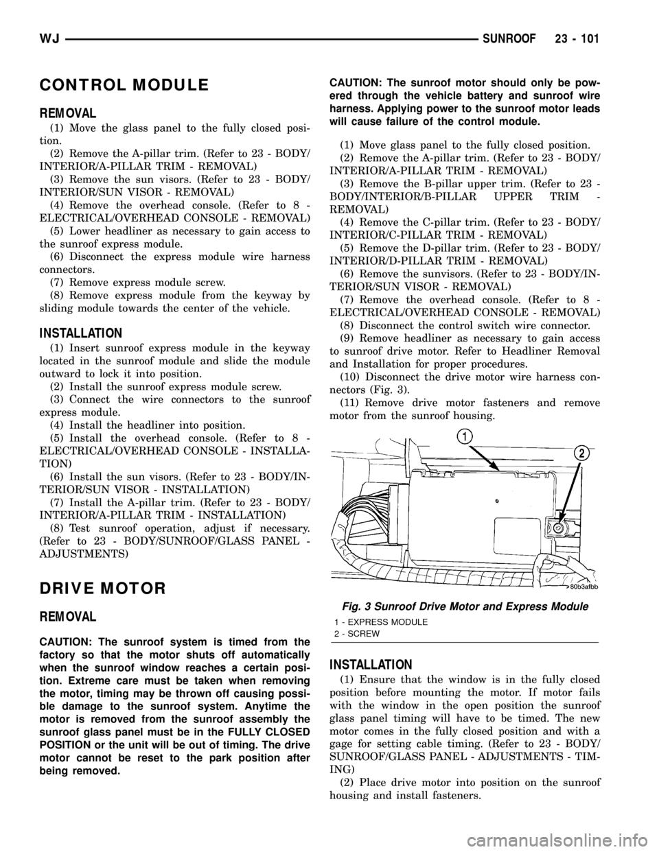
nectors (Fig. 3).
(11) Remove drive motor fasteners and remove
motor from the sunroof housing.
INSTALLATION
(1) Ensure that the window is in the fully closed
position before mounting the motor. If motor fails
with the window in the open position the sunroof
glass panel timing will have to be timed. The new
motor comes in the fully closed position and with a
gage for setting cable timing. (Refer to 23 - BODY/
SUNROOF/GLASS PANEL - ADJUSTMENTS - TIM-
ING)
(2) Place drive motor into position on the sunroof
housing and install fasteners.
Fig. 3 Sunroof Drive Motor and Express Module
1 - EXPRESS MODULE
2 - SCREW
WJSUNROOF 23 - 101