Window control fuse JEEP GRAND CHEROKEE 2003 WJ / 2.G Owner's Manual
[x] Cancel search | Manufacturer: JEEP, Model Year: 2003, Model line: GRAND CHEROKEE, Model: JEEP GRAND CHEROKEE 2003 WJ / 2.GPages: 2199, PDF Size: 76.01 MB
Page 1137 of 2199

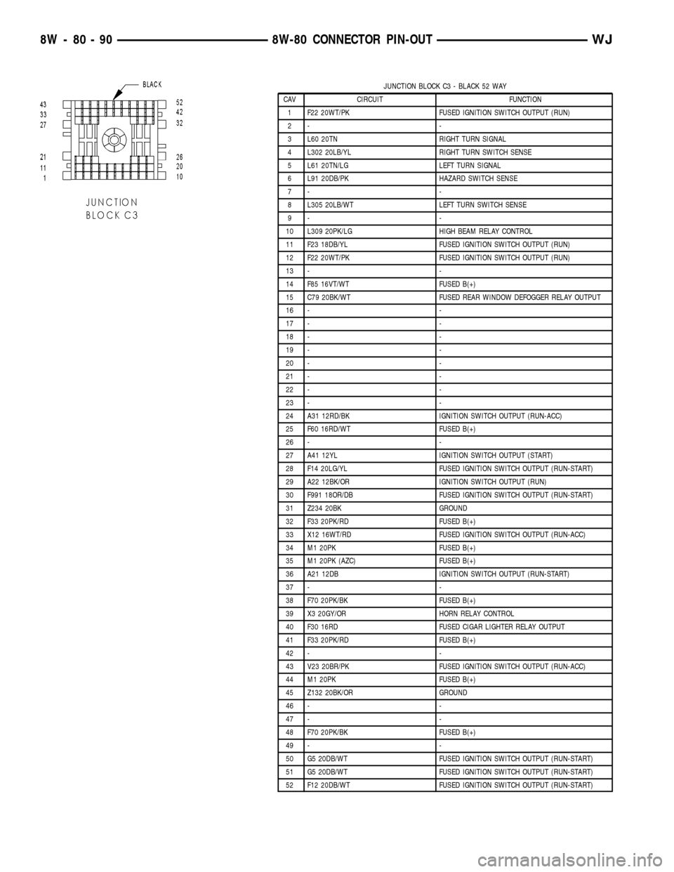
JUNCTION BLOCK C3 - BLACK 52 WAY
CAV CIRCUIT FUNCTION
1 F22 20WT/PK FUSED IGNITION SWITCH OUTPUT (RUN)
2- -
3 L60 20TN RIGHT TURN SIGNAL
4 L302 20LB/YL RIGHT TURN SWITCH SENSE
5 L61 20TN/LG LEFT TURN SIGNAL
6 L91 20DB/PK HAZARD SWITCH SENSE
7- -
8 L305 20LB/WT LEFT TURN SWITCH SENSE
9- -
10 L309 20PK/LG HIGH BEAM RELAY CONTROL
11 F23 18DB/YL FUSED IGNITION SWITCH OUTPUT (RUN)
12 F22 20WT/PK FUSED IGNITION SWITCH OUTPUT (RUN)
13 - -
14 F85 16VT/WT FUSED B(+)
15 C79 20BK/WT FUSED REAR WINDOW DEFOGGER RELAY OUTPUT
16 - -
17 - -
18 - -
19 - -
20 - -
21 - -
22 - -
23 - -
24 A31 12RD/BK IGNITION SWITCH OUTPUT (RUN-ACC)
25 F60 16RD/WT FUSED B(+)
26 - -
27 A41 12YL IGNITION SWITCH OUTPUT (START)
28 F14 20LG/YL FUSED IGNITION SWITCH OUTPUT (RUN-START)
29 A22 12BK/OR IGNITION SWITCH OUTPUT (RUN)
30 F991 18OR/DB FUSED IGNITION SWITCH OUTPUT (RUN-START)
31 Z234 20BK GROUND
32 F33 20PK/RD FUSED B(+)
33 X12 16WT/RD FUSED IGNITION SWITCH OUTPUT (RUN-ACC)
34 M1 20PK FUSED B(+)
35 M1 20PK (AZC) FUSED B(+)
36 A21 12DB IGNITION SWITCH OUTPUT (RUN-START)
37 - -
38 F70 20PK/BK FUSED B(+)
39 X3 20GY/OR HORN RELAY CONTROL
40 F30 16RD FUSED CIGAR LIGHTER RELAY OUTPUT
41 F33 20PK/RD FUSED B(+)
42 - -
43 V23 20BR/PK FUSED IGNITION SWITCH OUTPUT (RUN-ACC)
44 M1 20PK FUSED B(+)
45 Z132 20BK/OR GROUND
46 - -
47 - -
48 F70 20PK/BK FUSED B(+)
49 - -
50 G5 20DB/WT FUSED IGNITION SWITCH OUTPUT (RUN-START)
51 G5 20DB/WT FUSED IGNITION SWITCH OUTPUT (RUN-START)
52 F12 20DB/WT FUSED IGNITION SWITCH OUTPUT (RUN-START)
8W - 80 - 90 8W-80 CONNECTOR PIN-OUTWJ
Page 1145 of 2199

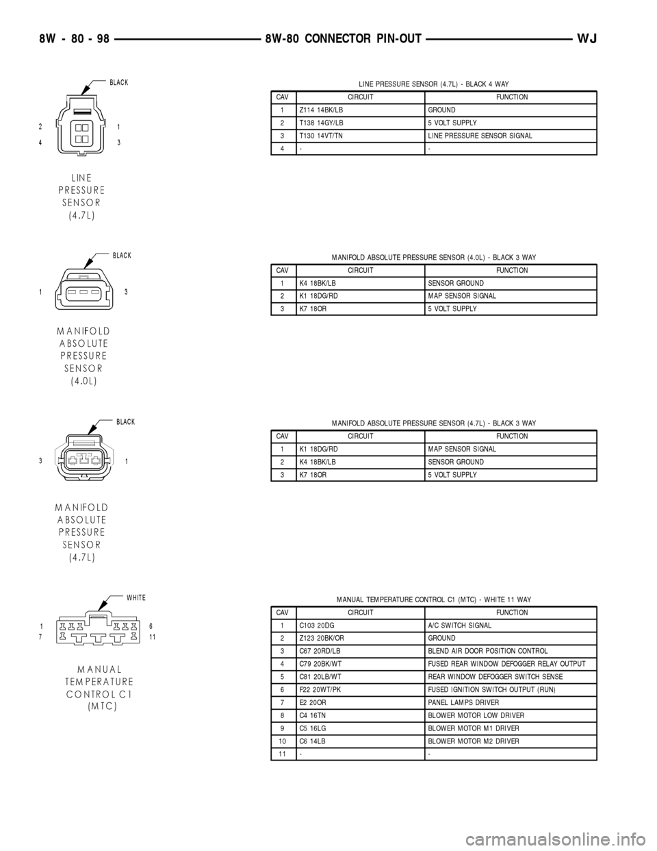
LINE PRESSURE SENSOR (4.7L) - BLACK 4 WAY
CAV CIRCUIT FUNCTION
1 Z114 14BK/LB GROUND
2 T138 14GY/LB 5 VOLT SUPPLY
3 T130 14VT/TN LINE PRESSURE SENSOR SIGNAL
4- -
MANIFOLD ABSOLUTE PRESSURE SENSOR (4.0L) - BLACK 3 WAY
CAV CIRCUIT FUNCTION
1 K4 18BK/LB SENSOR GROUND
2 K1 18DG/RD MAP SENSOR SIGNAL
3 K7 18OR 5 VOLT SUPPLY
MANIFOLD ABSOLUTE PRESSURE SENSOR (4.7L) - BLACK 3 WAY
CAV CIRCUIT FUNCTION
1 K1 18DG/RD MAP SENSOR SIGNAL
2 K4 18BK/LB SENSOR GROUND
3 K7 18OR 5 VOLT SUPPLY
MANUAL TEMPERATURE CONTROL C1 (MTC) - WHITE 11 WAY
CAV CIRCUIT FUNCTION
1 C103 20DG A/C SWITCH SIGNAL
2 Z123 20BK/OR GROUND
3 C67 20RD/LB BLEND AIR DOOR POSITION CONTROL
4 C79 20BK/WT FUSED REAR WINDOW DEFOGGER RELAY OUTPUT
5 C81 20LB/WT REAR WINDOW DEFOGGER SWITCH SENSE
6 F22 20WT/PK FUSED IGNITION SWITCH OUTPUT (RUN)
7 E2 20OR PANEL LAMPS DRIVER
8 C4 16TN BLOWER MOTOR LOW DRIVER
9 C5 16LG BLOWER MOTOR M1 DRIVER
10 C6 14LB BLOWER MOTOR M2 DRIVER
11 - -
8W - 80 - 98 8W-80 CONNECTOR PIN-OUTWJ
Page 2094 of 2199

open circuit to the fuse in the junction block as
required.
(5) The coil ground terminal cavity (85) is switched
to ground through the Powertrain Control Module
(PCM). There should be continuity between this cav-
ity and the A/C compressor clutch relay control cir-
cuit cavity of the PCM wire harness connector C
(gray) at all times. If not OK, repair the open circuit
as required.
REMOVAL
(1) Disconnect and isolate the battery negative
cable.
(2) Remove the cover from the Power Distribution
Center (PDC) (Fig. 11).
(3) Refer to the label on the PDC for compressor
clutch relay identification and location.
(4) Unplug the compressor clutch relay from the
PDC.
INSTALLATION
(1) Install the compressor clutch relay by aligning
the relay terminals with the cavities in the PDC and
pushing the relay firmly into place.
(2) Install the PDC cover.
(3) Connect the battery negative cable.
(4) Test the relay operation.
A/C HEATER CONTROL
DESCRIPTION
The manual temperature control HVAC system
uses a combination of electrical, and vacuum con-trols. The Automatic Zone Control (AZC) HVAC sys-
tem uses only electrical controls. These controls
provide the vehicle operator with a number of setting
options to help control the climate and comfort
within the vehicle. Refer to the owner's manual in
the vehicle glove box for more information on the
suggested operation and use of these controls.
Both a/c heater control panels are located on the
instrument panel inboard of the steering column and
below the radio (Fig. 12). Both control panels contain
rotary-type temperature control knob(s), a rotary-
type mode control switch knob, a rotary-type blower
motor speed switch knob and an air conditioning
compressor push button switch. The rear window
defogger push button switch is also located on a/c
heater control panel. The AZC control panel also fea-
tures a recirculation push button switch and a vac-
uum fluorescent display area.
OPERATION
The AZC control module uses infrared sensing
technology to control occupant comfort levels, not the
actual passenger compartment air temperature. Dual
infrared sensors mounted in the face of the control
unit independently measure the surface temperature
to maintain customer-perceived comfort temperature
under changing conditions. Dual Zone temperature
control provides wide side-to-side variation in comfort
temperature to exceed the needs of either front seat
occupant. This sensing system replaces interior air
temperature and solar sensors used to approximate
direct sensing control through complex control pro-
grams.
Fig. 11 POWER DISTRIBUTION CENTER (PDC)
1 - TRANSMISSION CONTROL MODULE (TCM)
2 - NEGATIVE CABLE
3 - POSITIVE CABLE
4 - POWER DISTRIBUTION CENTER (PDC)
Fig. 12 A/C HEATER CONTROL PANELS
WJCONTROLS 24 - 17
A/C COMPRESSOR CLUTCH RELAY (Continued)
Page 2106 of 2199

WARNING: ON VEHICLES EQUIPPED WITH AIR-
BAGS, DISABLE THE AIRBAG SYSTEM BEFORE
ATTEMPTING ANY STEERING WHEEL, STEERING
COLUMN, OR INSTRUMENT PANEL COMPONENT
DIAGNOSIS OR SERVICE. DISCONNECT AND ISO-
LATE THE BATTERY NEGATIVE (GROUND) CABLE,
THEN WAIT TWO MINUTES FOR THE AIRBAG SYS-
TEM CAPACITOR TO DISCHARGE BEFORE PER-
FORMING FURTHER DIAGNOSIS OR SERVICE. THIS
IS THE ONLY SURE WAY TO DISABLE THE AIRBAG
SYSTEM. FAILURE TO TAKE THE PROPER PRE-
CAUTIONS COULD RESULT IN AN ACCIDENTAL
AIRBAG DEPLOYMENT AND POSSIBLE PERSONAL
INJURY.
(1) Check for battery voltage at the fuse in the
Power Distribution Center (PDC). If OK, go to Step
2. If not OK, repair the shorted circuit or component
as required and replace the faulty fuse.
(2) Turn the ignition switch to the Off position.
Disconnect and isolate the battery negative cable.
Remove the a/c heater control from the instrument
panel. (Refer to 24 - HEATING & AIR CONDITION-
ING/CONTROLS/A/C HEATER CONTROL -
REMOVAL) Check for continuity between the ground
circuit cavity of the a/c heater control wire harness
connector and a good ground. There should be conti-
nuity. If OK, go to Step 3. If not OK, repair the open
circuit to ground as required.
(3) With the a/c heater control wire harness con-
nector unplugged, place the a/c heater mode control
switch knob in any position except the Off position.
Check for continuity between the ground circuit ter-
minal and each of the blower motor driver circuit ter-
minals of the a/c heater control as you move the
blower motor switch knob to each of the four speed
positions. There should be continuity at each driver
circuit terminal in only one blower motor switch
speed position. If OK, test and repair the blower
driver circuits between the a/c heater control connec-
tor and the blower motor resistor as required. If not
OK, replace the faulty a/c heater control unit.
REMOVAL
WARNING: ON VEHICLES EQUIPPED WITH AIR-
BAGS, DISABLE THE AIRBAG SYSTEM BEFORE
ATTEMPTING ANY STEERING WHEEL, STEERING
COLUMN, OR INSTRUMENT PANEL COMPONENT
DIAGNOSIS OR SERVICE. DISCONNECT AND ISO-
LATE THE BATTERY NEGATIVE (GROUND) CABLE,
THEN WAIT TWO MINUTES FOR THE AIRBAG SYS-
TEM CAPACITOR TO DISCHARGE BEFORE PER-
FORMING FURTHER DIAGNOSIS OR SERVICE. THIS
IS THE ONLY SURE WAY TO DISABLE THE AIRBAG
SYSTEM. FAILURE TO TAKE THE PROPER PRE-
CAUTIONS COULD RESULT IN AN ACCIDENTALAIRBAG DEPLOYMENT AND POSSIBLE PERSONAL
INJURY.
The blower motor switch cannot be adjusted or
repaired, and if faulty or damaged, the a/c heater
control must be replaced. (Refer to 24 - HEATING &
AIR CONDITIONING/CONTROLS/A/C HEATER
CONTROL - REMOVAL)
IN-CAR TEMPERATURE
SENSOR
DESCRIPTION
Models equipped with the optional Automatic Zone
Control (AZC) system use automatic dual zone tem-
perature control with infrared sensing technology.
The temperature sensor is located in the center
instrument panel, between the dual temperature
knobs of the AZC.
OPERATION
The Automatic Zone Control uses infrared sensing
technology to control occupant comfort levels, not the
actual passenger compartment air temperature. Dual
infrared sensors mounted in the face of the control
unit independently measure the surface temperature
to maintain customer-perceived comfort temperature
under changing conditions. Dual Zone temperature
control provides wide side-to-side variation in comfort
temperature to exceed the needs of either front seat
occupant. This sensing system replaces interior air
temperature and solar sensors used to approximate
direct sensing control through complex control pro-
grams.
The infrared temperature sensor cannot be
adjusted or repaired and, if faulty or damaged, the
AZC head must be replaced.
NOTE: The infrared sensor window may be perma-
nently damaged if any type of cosmetic vinyl dress-
ings are allowed to contact the lens. Avoid spraying
or wiping this area with any cleaner or conditioner.
This may result in impaired temperature sensing
and control.
REMOVAL
The infrared temperature sensor cannot be
adjusted or repaired and, if faulty or damaged, the
AZC head must be replaced. (Refer to 24 - HEATING
& AIR CONDITIONING/CONTROLS/A/C HEATER
CONTROL - REMOVAL)
WJCONTROLS 24 - 29
BLOWER MOTOR SWITCH (Continued)