bolt pattern JEEP GRAND CHEROKEE 2003 WJ / 2.G Owner's Manual
[x] Cancel search | Manufacturer: JEEP, Model Year: 2003, Model line: GRAND CHEROKEE, Model: JEEP GRAND CHEROKEE 2003 WJ / 2.GPages: 2199, PDF Size: 76.01 MB
Page 1283 of 2199
INSPECTION
Wipe the inserts clean and inspect for abnormal
wear patterns and for metal or other foreign material
imbedded in the lining. Normal main bearing insert
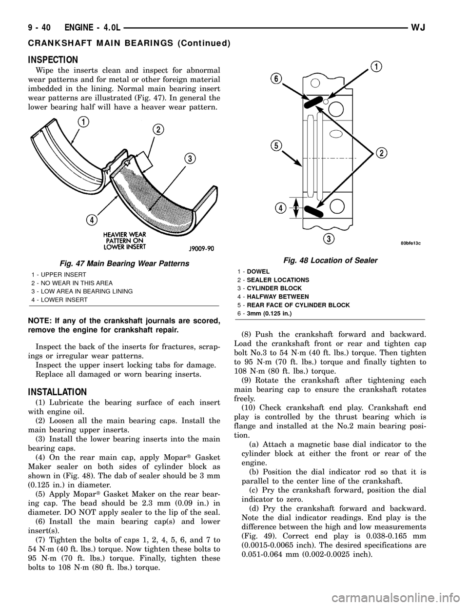
wear patterns are illustrated (Fig. 47). In general the
lower bearing half will have a heaver wear pattern.
NOTE: If any of the crankshaft journals are scored,
remove the engine for crankshaft repair.
Inspect the back of the inserts for fractures, scrap-
ings or irregular wear patterns.
Inspect the upper insert locking tabs for damage.
Replace all damaged or worn bearing inserts.
INSTALLATION
(1) Lubricate the bearing surface of each insert
with engine oil.
(2) Loosen all the main bearing caps. Install the
main bearing upper inserts.
(3) Install the lower bearing inserts into the main
bearing caps.
(4) On the rear main cap, apply MopartGasket
Maker sealer on both sides of cylinder block as
shown in (Fig. 48). The dab of sealer should be 3 mm
(0.125 in.) in diameter.
(5) Apply MopartGasket Maker on the rear bear-
ing cap. The bead should be 2.3 mm (0.09 in.) in
diameter. DO NOT apply sealer to the lip of the seal.
(6) Install the main bearing cap(s) and lower
insert(s).
(7) Tighten the bolts of caps 1, 2, 4, 5, 6, and 7 to
54 N´m (40 ft. lbs.) torque. Now tighten these bolts to
95 N´m (70 ft. lbs.) torque. Finally, tighten these
bolts to 108 N´m (80 ft. lbs.) torque.(8) Push the crankshaft forward and backward.
Load the crankshaft front or rear and tighten cap
bolt No.3 to 54 N´m (40 ft. lbs.) torque. Then tighten
to 95 N´m (70 ft. lbs.) torque and finally tighten to
108 N´m (80 ft. lbs.) torque.
(9) Rotate the crankshaft after tightening each
main bearing cap to ensure the crankshaft rotates
freely.
(10) Check crankshaft end play. Crankshaft end
play is controlled by the thrust bearing which is
flange and installed at the No.2 main bearing posi-
tion.
(a) Attach a magnetic base dial indicator to the
cylinder block at either the front or rear of the
engine.
(b) Position the dial indicator rod so that it is
parallel to the center line of the crankshaft.
(c) Pry the crankshaft forward, position the dial
indicator to zero.
(d) Pry the crankshaft forward and backward.
Note the dial indicator readings. End play is the
difference between the high and low measurements
(Fig. 49). Correct end play is 0.038-0.165 mm
(0.0015-0.0065 inch). The desired specifications are
0.051-0.064 mm (0.002-0.0025 inch).
Fig. 47 Main Bearing Wear Patterns
1 - UPPER INSERT
2 - NO WEAR IN THIS AREA
3 - LOW AREA IN BEARING LINING
4 - LOWER INSERT
Fig. 48 Location of Sealer
1-DOWEL
2-SEALER LOCATIONS
3-CYLINDER BLOCK
4-HALFWAY BETWEEN
5-REAR FACE OF CYLINDER BLOCK
6-3mm (0.125 in.)
9 - 40 ENGINE - 4.0LWJ
CRANKSHAFT MAIN BEARINGS (Continued)
Page 1351 of 2199
(4) For rocker arm installation on cylinders 1 and
7 Rotate the crankshaft until cylinder #2 is at TDC
compression stroke.
(5) Using special tool 8516 press downward on the
valve spring, install rocker arm (Fig. 44).
(6) Install the cylinder head cover (Refer to 9 -
ENGINE/CYLINDER HEAD/CYLINDER HEAD
COVER(S) - INSTALLATION).
VALVE SPRINGS
DESCRIPTION
The valve springs are made from high strength
chrome silicon steel. The springs are common for
intake and exhaust applications. The valve spring
seat is integral with the valve stem seal, which is a
positive type seal to control lubrication.
VALVE STEM SEALS
DESCRIPTION
The valve stem seals are made of rubber and incor-
porate an integral steel valve spring seat. The inte-
gral garter spring maintains consistent lubrication
control to the valve stems.
ENGINE BLOCK
DESCRIPTION
The cylinder block is made of cast iron. The block
is a closed deck design with the left bank forward. To
provide high rigidity and improved NVH an
enhanced compacted graphite bedplate is bolted to
the block. The block design allows coolant flow
between the cylinders bores, and an internal coolant
bypass to a single poppet inlet thermostat is included
in the cast aluminum front cover.
STANDARD PROCEDUREÐCYLINDER BORE
HONING
Before honing, stuff plenty of clean shop towels
under the bores and over the crankshaft to keep
abrasive materials from entering the crankshaft
area.
(1) Used carefully, the Cylinder Bore Sizing Hone
C-823, equipped with 220 grit stones, is the best tool
for this job. In addition to deglazing, it will reduce
taper and out-of-round, as well as removing light
scuffing, scoring and scratches. Usually, a few strokes
will clean up a bore and maintain the required lim-
its.CAUTION: DO NOT use rigid type hones to remove
cylinder wall glaze.
(2) Deglazing of the cylinder walls may be done if
the cylinder bore is straight and round. Use a cylin-
der surfacing hone, Honing Tool C-3501, equipped
with 280 grit stones (C-3501-3810). about 20-60
strokes, depending on the bore condition, will be suf-
ficient to provide a satisfactory surface. Using honing
oil C-3501-3880, or a light honing oil, available from
major oil distributors.
CAUTION: DO NOT use engine or transmission oil,
mineral spirits, or kerosene.
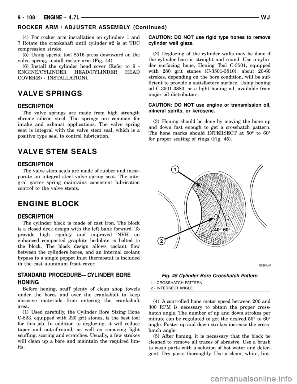
(3) Honing should be done by moving the hone up
and down fast enough to get a crosshatch pattern.
The hone marks should INTERSECT at 50É to 60É
for proper seating of rings (Fig. 45).
(4) A controlled hone motor speed between 200 and
300 RPM is necessary to obtain the proper cross-
hatch angle. The number of up and down strokes per
minute can be regulated to get the desired 50É to 60É
angle. Faster up and down strokes increase the cross-
hatch angle.
(5) After honing, it is necessary that the block be
cleaned to remove all traces of abrasive. Use a brush
to wash parts with a solution of hot water and deter-
gent. Dry parts thoroughly. Use a clean, white, lint-
Fig. 45 Cylinder Bore Crosshatch Pattern
1 - CROSSHATCH PATTERN
2 - INTERSECT ANGLE
9 - 108 ENGINE - 4.7LWJ
ROCKER ARM / ADJUSTER ASSEMBLY (Continued)
Page 1352 of 2199
free cloth to check that the bore is clean. Oil the
bores after cleaning to prevent rusting.
CLEANING
Thoroughly clean the oil pan and engine block gas-
ket surfaces.
Use compressed air to clean out:
²The galley at the oil filter adaptor hole.
²The front and rear oil galley holes.
²The feed holes for the crankshaft main bearings.
Once the block has been completely cleaned, apply
Loctite PST pipe sealant with Teflon 592 to the
threads of the front and rear oil galley plugs. Tighten
the plugs to 34 N´m (25 ft. lbs.) torque.
INSPECTION
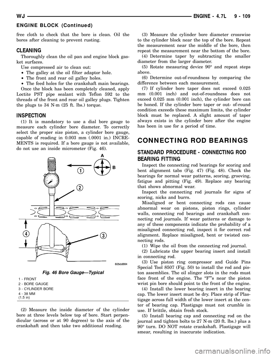
(1) It is mandatory to use a dial bore gauge to
measure each cylinder bore diameter. To correctly
select the proper size piston, a cylinder bore gauge,
capable of reading in 0.003 mm (.0001 in.) INCRE-
MENTS is required. If a bore gauge is not available,
do not use an inside micrometer (Fig. 46).
(2) Measure the inside diameter of the cylinder
bore at three levels below top of bore. Start perpen-
dicular (across or at 90 degrees) to the axis of the
crankshaft and then take two additional reading.(3) Measure the cylinder bore diameter crosswise
to the cylinder block near the top of the bore. Repeat
the measurement near the middle of the bore, then
repeat the measurement near the bottom of the bore.
(4) Determine taper by subtracting the smaller
diameter from the larger diameter.
(5) Rotate measuring device 90É and repeat steps
above.
(6) Determine out-of-roundness by comparing the
difference between each measurement.
(7) If cylinder bore taper does not exceed 0.025
mm (0.001 inch) and out-of-roundness does not
exceed 0.025 mm (0.001 inch), the cylinder bore can
be honed. If the cylinder bore taper or out- of-round
condition exceeds these maximum limits, the cylinder
block must be replaced. A slight amount of taper
always exists in the cylinder bore after the engine
has been in use for a period of time.
CONNECTING ROD BEARINGS
STANDARD PROCEDURE - CONNECTING ROD
BEARING FITTING
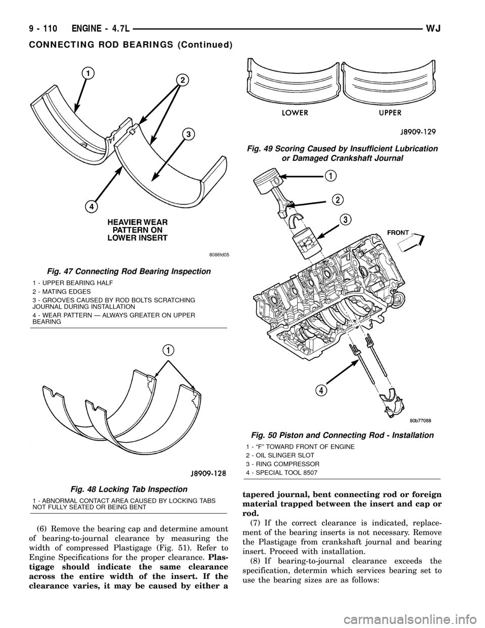
Inspect the connecting rod bearings for scoring and
bent alignment tabs (Fig. 47) (Fig. 48). Check the
bearings for normal wear patterns, scoring, grooving,
fatigue and pitting (Fig. 49). Replace any bearing
that shows abnormal wear.
Inspect the connecting rod journals for signs of
scoring, nicks and burrs.
Misaligned or bent connecting rods can cause
abnormal wear on pistons, piston rings, cylinder
walls, connecting rod bearings and crankshaft con-
necting rod journals. If wear patterns or damage to
any of these components indicate the probability of a
misaligned connecting rod, inspect it for correct rod
alignment. Replace misaligned, bent or twisted con-
necting rods.
(1) Wipe the oil from the connecting rod journal.
(2) Lubricate the upper bearing insert and install
in connecting rod.
(3) Use piston ring compressor and Guide Pins
Special Tool 8507 (Fig. 50) to install the rod and pis-
ton assemblies. The oil slinger slots in the rods must
face front of the engine. The ªFº's near the piston
wrist pin bore should point to the front of the engine.
(4) Install the lower bearing insert in the bearing
cap. The lower insert must be dry. Place strip of Plas-
tigage across full width of the lower insert at the cen-
ter of bearing cap. Plastigage must not crumble in
use. If brittle, obtain fresh stock.
(5) Install bearing cap and connecting rod on the
journal and tighten bolts to 27 N´m (20 ft. lbs.) plus a
90É turn. DO NOT rotate crankshaft. Plastigage will
smear, resulting in inaccurate indication.
Fig. 46 Bore GaugeÐTypical
1 - FRONT
2 - BORE GAUGE
3 - CYLINDER BORE
4-38MM
(1.5 in)
WJENGINE - 4.7L 9 - 109
ENGINE BLOCK (Continued)
Page 1353 of 2199
(6) Remove the bearing cap and determine amount
of bearing-to-journal clearance by measuring the
width of compressed Plastigage (Fig. 51). Refer to
Engine Specifications for the proper clearance.Plas-
tigage should indicate the same clearance
across the entire width of the insert. If the
clearance varies, it may be caused by either atapered journal, bent connecting rod or foreign
material trapped between the insert and cap or
rod.
(7) If the correct clearance is indicated, replace-
ment of the bearing inserts is not necessary. Remove
the Plastigage from crankshaft journal and bearing
insert. Proceed with installation.
(8) If bearing-to-journal clearance exceeds the
specification, determin which services bearing set to
use the bearing sizes are as follows:
Fig. 47 Connecting Rod Bearing Inspection
1 - UPPER BEARING HALF
2 - MATING EDGES
3 - GROOVES CAUSED BY ROD BOLTS SCRATCHING
JOURNAL DURING INSTALLATION
4 - WEAR PATTERN Ð ALWAYS GREATER ON UPPER
BEARING
Fig. 48 Locking Tab Inspection
1 - ABNORMAL CONTACT AREA CAUSED BY LOCKING TABS
NOT FULLY SEATED OR BEING BENT
Fig. 49 Scoring Caused by Insufficient Lubrication
or Damaged Crankshaft Journal
Fig. 50 Piston and Connecting Rod - Installation
1 - ªFº TOWARD FRONT OF ENGINE
2 - OIL SLINGER SLOT
3 - RING COMPRESSOR
4 - SPECIAL TOOL 8507
9 - 110 ENGINE - 4.7LWJ
CONNECTING ROD BEARINGS (Continued)
Page 1371 of 2199
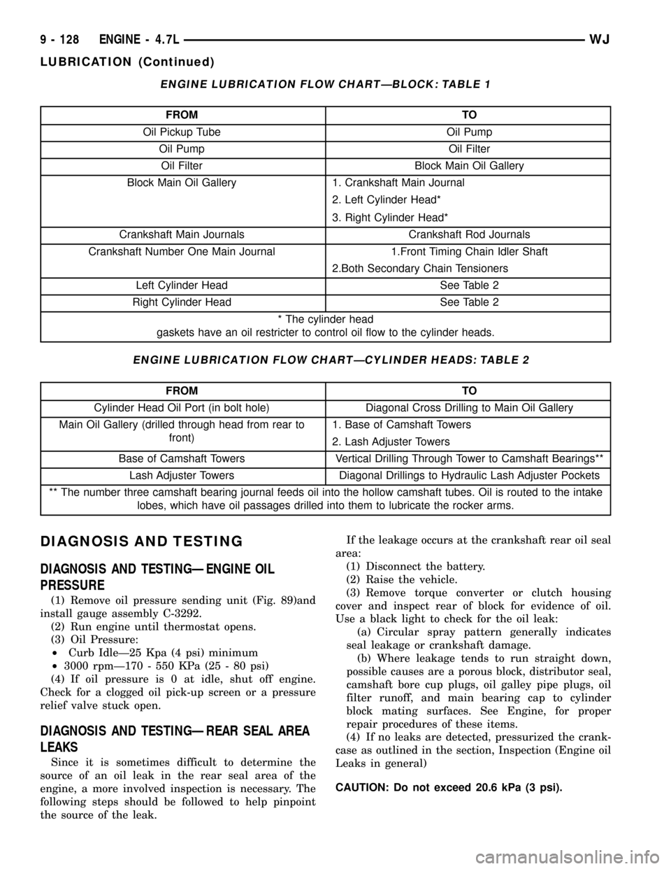
ENGINE LUBRICATION FLOW CHARTÐBLOCK: TABLE 1
FROM TO
Oil Pickup Tube Oil Pump
Oil Pump Oil Filter
Oil Filter Block Main Oil Gallery
Block Main Oil Gallery 1. Crankshaft Main Journal
2. Left Cylinder Head*
3. Right Cylinder Head*
Crankshaft Main Journals Crankshaft Rod Journals
Crankshaft Number One Main Journal 1.Front Timing Chain Idler Shaft
2.Both Secondary Chain Tensioners
Left Cylinder Head See Table 2
Right Cylinder Head See Table 2
* The cylinder head
gaskets have an oil restricter to control oil flow to the cylinder heads.
ENGINE LUBRICATION FLOW CHARTÐCYLINDER HEADS: TABLE 2
FROM TO
Cylinder Head Oil Port (in bolt hole) Diagonal Cross Drilling to Main Oil Gallery
Main Oil Gallery (drilled through head from rear to
front)1. Base of Camshaft Towers
2. Lash Adjuster Towers
Base of Camshaft Towers Vertical Drilling Through Tower to Camshaft Bearings**
Lash Adjuster Towers Diagonal Drillings to Hydraulic Lash Adjuster Pockets
** The number three camshaft bearing journal feeds oil into the hollow camshaft tubes. Oil is routed to the intake
lobes, which have oil passages drilled into them to lubricate the rocker arms.
DIAGNOSIS AND TESTING
DIAGNOSIS AND TESTINGÐENGINE OIL
PRESSURE
(1) Remove oil pressure sending unit (Fig. 89)and
install gauge assembly C-3292.
(2) Run engine until thermostat opens.
(3) Oil Pressure:
²Curb IdleÐ25 Kpa (4 psi) minimum
²3000 rpmÐ170 - 550 KPa (25 - 80 psi)
(4) If oil pressure is 0 at idle, shut off engine.
Check for a clogged oil pick-up screen or a pressure
relief valve stuck open.
DIAGNOSIS AND TESTINGÐREAR SEAL AREA
LEAKS
Since it is sometimes difficult to determine the
source of an oil leak in the rear seal area of the
engine, a more involved inspection is necessary. The
following steps should be followed to help pinpoint
the source of the leak.If the leakage occurs at the crankshaft rear oil seal
area:
(1) Disconnect the battery.
(2) Raise the vehicle.
(3) Remove torque converter or clutch housing
cover and inspect rear of block for evidence of oil.
Use a black light to check for the oil leak:
(a) Circular spray pattern generally indicates
seal leakage or crankshaft damage.
(b) Where leakage tends to run straight down,
possible causes are a porous block, distributor seal,
camshaft bore cup plugs, oil galley pipe plugs, oil
filter runoff, and main bearing cap to cylinder
block mating surfaces. See Engine, for proper
repair procedures of these items.
(4) If no leaks are detected, pressurized the crank-
case as outlined in the section, Inspection (Engine oil
Leaks in general)
CAUTION: Do not exceed 20.6 kPa (3 psi).
9 - 128 ENGINE - 4.7LWJ
LUBRICATION (Continued)
Page 1559 of 2199
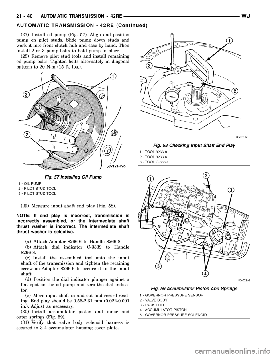
(27) Install oil pump (Fig. 57). Align and position
pump on pilot studs. Slide pump down studs and
work it into front clutch hub and case by hand. Then
install 2 or 3 pump bolts to hold pump in place.
(28) Remove pilot stud tools and install remaining
oil pump bolts. Tighten bolts alternately in diagonal
pattern to 20 N´m (15 ft. lbs.).
(29) Measure input shaft end play (Fig. 58).
NOTE: If end play is incorrect, transmission is
incorrectly assembled, or the intermediate shaft
thrust washer is incorrect. The intermediate shaft
thrust washer is selective.
(a) Attach Adapter 8266-6 to Handle 8266-8.
(b) Attach dial indicator C-3339 to Handle
8266-8.
(c) Install the assembled tool onto the input
shaft of the transmission and tighten the retaining
screw on Adapter 8266-6 to secure it to the input
shaft.
(d) Position the dial indicator plunger against a
flat spot on the oil pump and zero the dial indica-
tor.
(e) Move input shaft in and out and record read-
ing. End play should be 0.56-2.31 mm (0.022-0.091
in.). Adjust as necessary.
(30) Install accumulator piston and inner and
outer springs (Fig. 59).
(31) Verify that valve body solenoid harness is
secured in 3-4 accumulator housing cover plate.
Fig. 57 Installing Oil Pump
1 - OIL PUMP
2 - PILOT STUD TOOL
3 - PILOT STUD TOOL
Fig. 58 Checking Input Shaft End Play
1 - TOOL 8266-8
2 - TOOL 8266-6
3 - TOOL C-3339
Fig. 59 Accumulator Piston And Springs
1 - GOVERNOR PRESSURE SENSOR
2 - VALVE BODY
3 - PARK ROD
4 - ACCUMULATOR PISTON
5 - GOVERNOR PRESSURE SOLENOID
21 - 40 AUTOMATIC TRANSMISSION - 42REWJ
AUTOMATIC TRANSMISSION - 42RE (Continued)
Page 1560 of 2199
(32) Install valve body as follows:
(a) Align and carefully insert park rod into pawl.
Rod will make click noise as it enters pawl. Move
rod slightly to check engagement.
(b) Align and seat valve body on case. Be sure
manual lever shaft and overdrive connector are
fully seated in case. Also be sure valve body wiring
is not pinched or kinked.
(c) Install and start all valve body attaching
bolts by hand. Then tighten bolts evenly, in a diag-
onal pattern to 12 N´m (105 in. lbs.) torque. Do not
overtighten valve body bolts. This could result in
distortion and cross leakage after installation.
CAUTION: It is possible for the park rod to displace
into a cavity just above the pawl sprag during
installation. Make sure the rod is actually engaged
in the pawl and has not displaced into the cavity.
(33) Install new filter on valve body. Tighten filter
screws to 4 N´m (35 in. lbs.).
(34) Adjust front and rear bands.
(35) Install seal on park/neutral position switch.
Then install and tighten switch to 34 N´m (25 ft.
lbs.).
(36) Install magnet in oil pan. Magnet goes on
small protrusion at corner of pan.
(37) Position new oil pan gasket on case and
install oil pan. Tighten pan bolts to 17 N´m (13 ft.
lbs.).
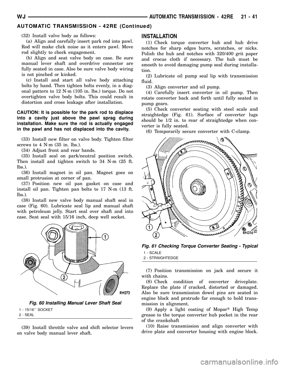
(38) Install new valve body manual shaft seal in
case (Fig. 60). Lubricate seal lip and manual shaft
with petroleum jelly. Start seal over shaft and into
case. Seat seal with 15/16 inch, deep well socket.
(39) Install throttle valve and shift selector levers
on valve body manual lever shaft.INSTALLATION
(1) Check torque converter hub and hub drive
notches for sharp edges burrs, scratches, or nicks.
Polish the hub and notches with 320/400 grit paper
and crocus cloth if necessary. The hub must be
smooth to avoid damaging pump seal during installa-
tion.
(2) Lubricate oil pump seal lip with transmission
fluid.
(3) Align converter and oil pump.
(4) Carefully insert converter in oil pump. Then
rotate converter back and forth until fully seated in
pump gears.
(5) Check converter seating with steel scale and
straightedge (Fig. 61). Surface of converter lugs
should be 1/2 in. to rear of straightedge when con-
verter is fully seated.
(6) Temporarily secure converter with C-clamp.
(7) Position transmission on jack and secure it
with chains.
(8) Check condition of converter driveplate.
Replace the plate if cracked, distorted or damaged.
Also be sure transmission dowel pins are seated in
engine block and protrude far enough to hold trans-
mission in alignment.
(9) Apply a light coating of MopartHigh Temp
grease to the torque converter hub pocket in the rear
of the crankshaft
(10) Raise transmission and align converter with
drive plate and converter housing with engine block.
Fig. 60 Installing Manual Lever Shaft Seal
1 - 15/1688SOCKET
2 - SEAL
Fig. 61 Checking Torque Converter Seating - Typical
1 - SCALE
2 - STRAIGHTEDGE
WJAUTOMATIC TRANSMISSION - 42RE 21 - 41
AUTOMATIC TRANSMISSION - 42RE (Continued)
Page 1624 of 2199
CAUTION: Be sure the shoulder on the inside diam-
eter of the bearing is facing forward.
(8) Verify that splines in overdrive planetary gear
and overrunning clutch hub are aligned with Align-
ment Tool 6227-2. Overdrive unit cannot be installed
if splines are not aligned. If splines have rotated out
of alignment, unit will have to be disassembled to
realign splines.
(9) Carefully slide Alignment Tool 6227-2 out of
overdrive planetary gear and overrunning clutch
splines.
(10) Raise overdrive unit and carefully slide it
straight onto intermediate shaft. Insert park rod into
park lock reaction plug at same time. Avoid tilting
overdrive during installation as this could cause
planetary gear and overrunning clutch splines to
rotate out of alignment. If this occurs, it will be nec-essary to remove and disassemble overdrive unit to
realign splines.
(11) Work overdrive unit forward on intermediate
shaft until seated against transmission case.
(12) Install bolts attaching overdrive unit to trans-
mission unit. Tighten bolts in diagonal pattern to 34
N´m (25 ft-lbs).
(13) Connect the transmission speed sensor and
overdrive wiring connectors.
(14) Install the transfer case, if equipped.
(15) Align and install rear propeller shaft, if nec-
essary. (Refer to 3 - DIFFERENTIAL & DRIVELINE/
PROPELLER SHAFT/PROPELLER SHAFT -
INSTALLATION)
OVERRUNNING CLUTCH
CAM/OVERDRIVE PISTON
RETAINER
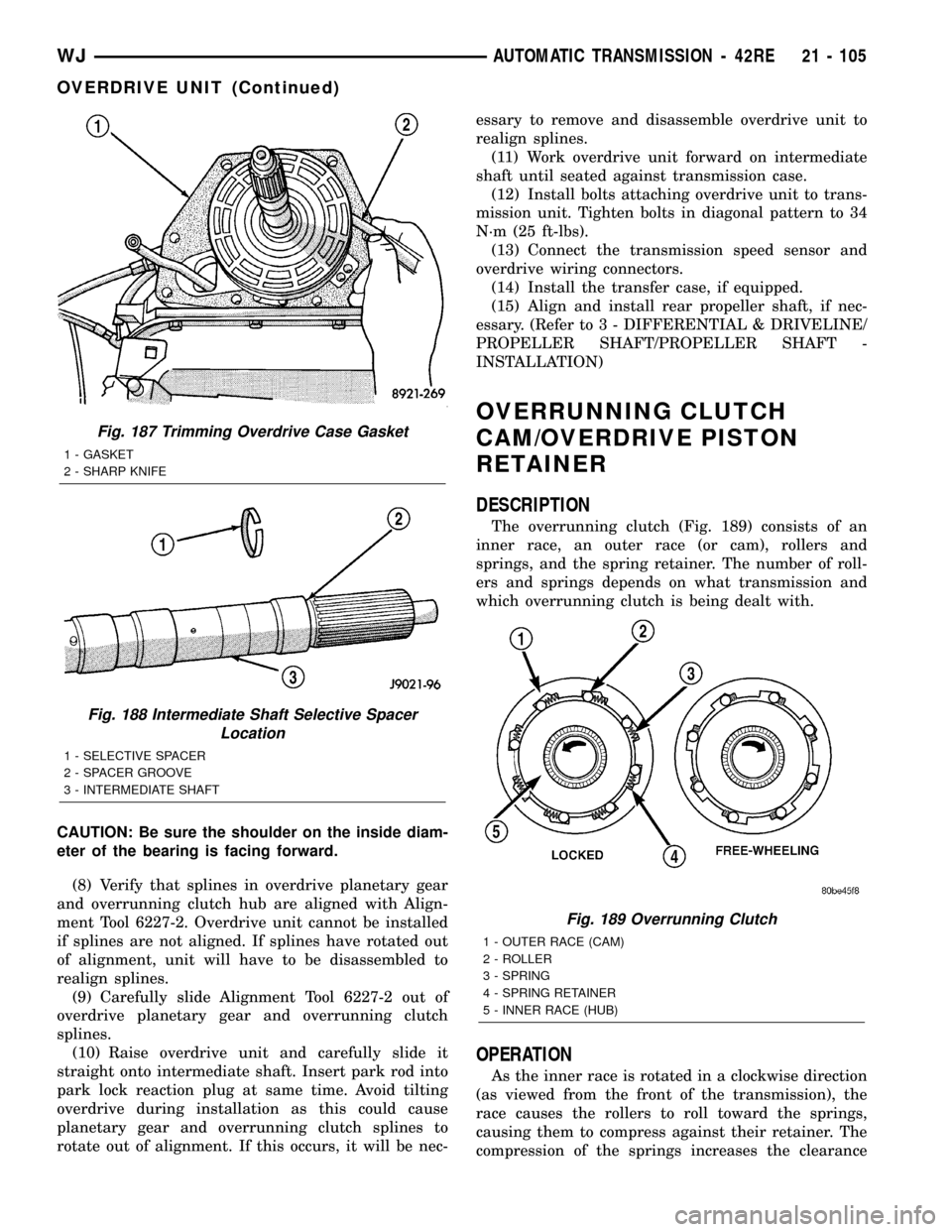
DESCRIPTION
The overrunning clutch (Fig. 189) consists of an
inner race, an outer race (or cam), rollers and
springs, and the spring retainer. The number of roll-
ers and springs depends on what transmission and
which overrunning clutch is being dealt with.
OPERATION
As the inner race is rotated in a clockwise direction
(as viewed from the front of the transmission), the
race causes the rollers to roll toward the springs,
causing them to compress against their retainer. The
compression of the springs increases the clearance
Fig. 187 Trimming Overdrive Case Gasket
1 - GASKET
2 - SHARP KNIFE
Fig. 188 Intermediate Shaft Selective Spacer
Location
1 - SELECTIVE SPACER
2 - SPACER GROOVE
3 - INTERMEDIATE SHAFT
Fig. 189 Overrunning Clutch
1 - OUTER RACE (CAM)
2 - ROLLER
3 - SPRING
4 - SPRING RETAINER
5 - INNER RACE (HUB)
WJAUTOMATIC TRANSMISSION - 42RE 21 - 105
OVERDRIVE UNIT (Continued)
Page 1799 of 2199

TRANSFER CASE - NV242
TABLE OF CONTENTS
page page
TRANSFER CASE - NV242
DESCRIPTION........................280
OPERATION..........................281
DIAGNOSIS AND TESTING - TRANSFER
CASE - NV242.......................281
REMOVAL............................282
DISASSEMBLY........................282
CLEANING...........................292
INSPECTION.........................293
ASSEMBLY...........................295
INSTALLATION........................307
SPECIFICATIONS
TRANSFER CASE - NV242.............308
SPECIAL TOOLS
TRANSFER CASE - NV242.............308
FLUID
STANDARD PROCEDURE - FLUID DRAIN/
REFILL............................310FRONT OUTPUT SHAFT SEAL
REMOVAL............................310
INSTALLATION........................310
POSITION SENSOR
DESCRIPTION........................311
OPERATION..........................311
REMOVAL............................312
INSTALLATION........................312
REAR RETAINER BUSHING AND SEAL -
NV242HD
REMOVAL............................312
INSTALLATION........................312
SHIFT CABLE
REMOVAL............................313
INSTALLATION........................313
TRANSFER CASE - NV242
DESCRIPTION
The NV242 is a full transfer case (Fig. 1). It pro-
vides full time 2-wheel, or 4-wheel drive operation.
A differential in the transfer case is used to control
torque transfer to the front and rear axles. A low
range gear provides increased low speed torque capa-
bility for off road operation. The low range provides a
2.72:1 reduction ratio.
The geartrain is mounted in two aluminum case
halves attached with bolts. The mainshaft front and
rear bearings are mounted in aluminum retainer
housings bolted to the case halves.
TRANSFER CASE IDENTIFICATION
Two versions of the NV242 are used in the WJ
vehicles, NV242LD and NV242HD. The two transfer
cases can be distinguished from one another by the
rear output shaft retainer. The NV242LD uses a rub-
ber boot to cover the rear output shaft, while the
NV242HD uses a cast aluminum housing. Other than
this difference, the two transfer cases are serviced
the same.
A circular ID tag is attached to the rear case of
each transfer case (Fig. 2). The ID tag provides the
transfer case model number, assembly number, serial
number, and low range ratio.The transfer case serial number also represents
the date of build.
SHIFT MECHANISM
Operating ranges are selected with a lever in the
floor mounted shifter assembly. The shift lever is con-
nected to the transfer case range lever by an adjust-
able cable. A straight line shift pattern is used.
Range positions are marked on the shifter bezel.
Fig. 1 NV242 Transfer Case
21 - 280 TRANSFER CASE - NV242WJ