Bolts JEEP GRAND CHEROKEE 2003 WJ / 2.G Workshop Manual
[x] Cancel search | Manufacturer: JEEP, Model Year: 2003, Model line: GRAND CHEROKEE, Model: JEEP GRAND CHEROKEE 2003 WJ / 2.GPages: 2199, PDF Size: 76.01 MB
Page 1903 of 2199
(3) Install fascia, refer to (Refer to 13 - FRAMES
& BUMPERS/BUMPERS/FRONT FASCIA - INSTAL-
LATION).
HEADLAMP MOUNTING
MODULE
REMOVAL
CAUTION: Take special care when handling the
HMM not to damage the upper mounting tabs. Step
#3 must be performed prior to removing HMM from
the vehicle to prevent damage to HMM.
(1) Remove fascia, refer to (Refer to 13 - FRAMES
& BUMPERS/BUMPERS/FRONT FASCIA - REMOV-
AL).
(2) Remove inner fender liner.
(3) Reach into the wheelhouse opening and disen-
gage the retainer attaching the HMM to each side of
the body.
(4) Remove bolts attaching headlamp mounting
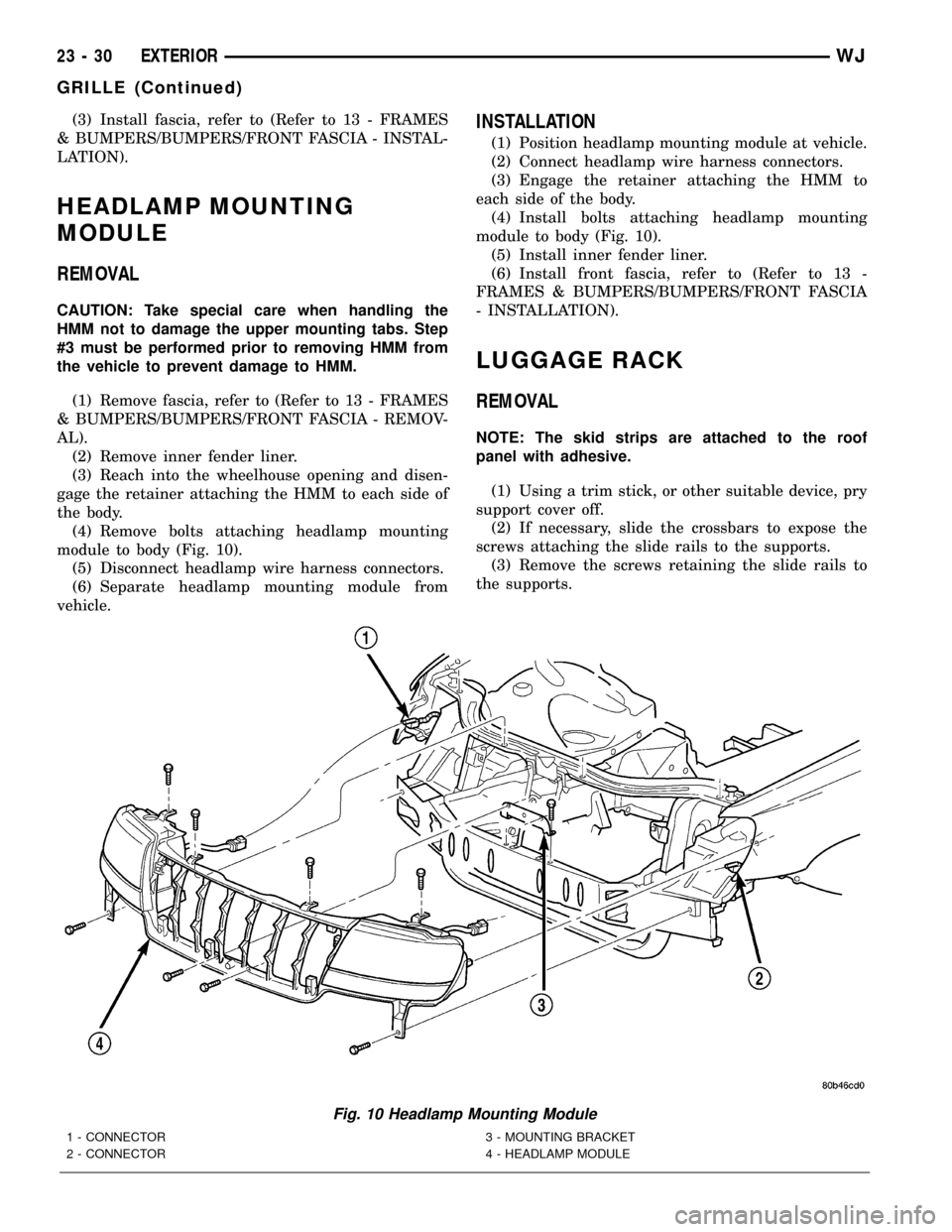
module to body (Fig. 10).
(5) Disconnect headlamp wire harness connectors.
(6) Separate headlamp mounting module from
vehicle.
INSTALLATION
(1) Position headlamp mounting module at vehicle.
(2) Connect headlamp wire harness connectors.
(3) Engage the retainer attaching the HMM to
each side of the body.
(4) Install bolts attaching headlamp mounting
module to body (Fig. 10).
(5) Install inner fender liner.
(6) Install front fascia, refer to (Refer to 13 -
FRAMES & BUMPERS/BUMPERS/FRONT FASCIA
- INSTALLATION).
LUGGAGE RACK
REMOVAL
NOTE: The skid strips are attached to the roof
panel with adhesive.
(1) Using a trim stick, or other suitable device, pry
support cover off.
(2) If necessary, slide the crossbars to expose the
screws attaching the slide rails to the supports.
(3) Remove the screws retaining the slide rails to
the supports.
Fig. 10 Headlamp Mounting Module
1 - CONNECTOR
2 - CONNECTOR3 - MOUNTING BRACKET
4 - HEADLAMP MODULE
23 - 30 EXTERIORWJ
GRILLE (Continued)
Page 1905 of 2199
ROCK RAIL
REMOVAL
(1) Remove the bolts and remove the rock rail.
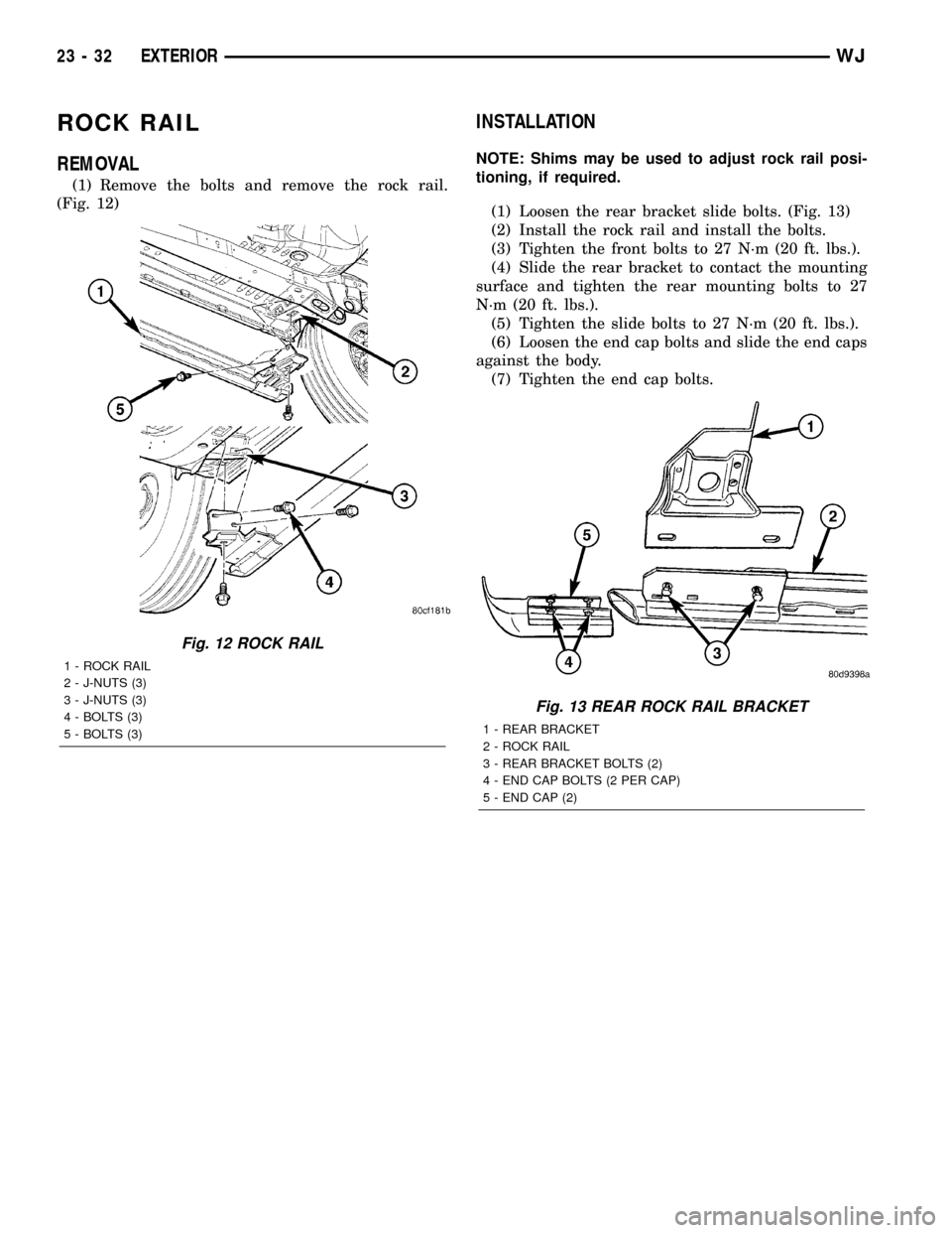
(Fig. 12)
INSTALLATION
NOTE: Shims may be used to adjust rock rail posi-
tioning, if required.
(1) Loosen the rear bracket slide bolts. (Fig. 13)
(2) Install the rock rail and install the bolts.
(3) Tighten the front bolts to 27 N´m (20 ft. lbs.).
(4) Slide the rear bracket to contact the mounting
surface and tighten the rear mounting bolts to 27
N´m (20 ft. lbs.).
(5) Tighten the slide bolts to 27 N´m (20 ft. lbs.).
(6) Loosen the end cap bolts and slide the end caps
against the body.
(7) Tighten the end cap bolts.
Fig. 12 ROCK RAIL
1 - ROCK RAIL
2 - J-NUTS (3)
3 - J-NUTS (3)
4 - BOLTS (3)
5 - BOLTS (3)
Fig. 13 REAR ROCK RAIL BRACKET
1 - REAR BRACKET
2 - ROCK RAIL
3 - REAR BRACKET BOLTS (2)
4 - END CAP BOLTS (2 PER CAP)
5 - END CAP (2)
23 - 32 EXTERIORWJ
Page 1906 of 2199
HOOD
TABLE OF CONTENTS
page page
GAS PROP
REMOVAL.............................33
INSTALLATION.........................33
HINGE
REMOVAL.............................33
INSTALLATION.........................33
HOOD
REMOVAL.............................33
INSTALLATION.........................34
ADJUSTMENTS
HOOD ADJUSTMENT..................34INSULATION
REMOVAL.............................34
INSTALLATION.........................34
LATCH
REMOVAL.............................34
INSTALLATION.........................34
LATCH RELEASE CABLE
REMOVAL.............................35
INSTALLATION.........................35
GAS PROP
REMOVAL
(1) Raise and support hood.
(2) Using a small flat blade, pry the retainer
attaching hood support prop to lower ball stud.
(3) Slide retainer attaching hood support prop
upper ball stud downward.
(4) Disconnect hood support prop from lower ball
stud and rotate support prop upward and disconnect
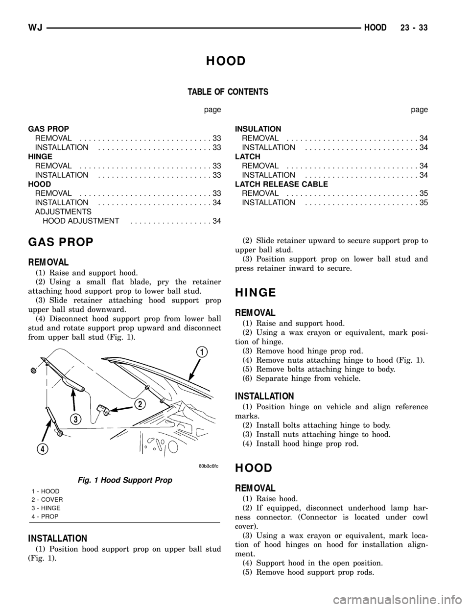
from upper ball stud (Fig. 1).
INSTALLATION
(1) Position hood support prop on upper ball stud
(Fig. 1).(2) Slide retainer upward to secure support prop to
upper ball stud.
(3) Position support prop on lower ball stud and
press retainer inward to secure.
HINGE
REMOVAL
(1) Raise and support hood.
(2) Using a wax crayon or equivalent, mark posi-
tion of hinge.
(3) Remove hood hinge prop rod.
(4) Remove nuts attaching hinge to hood (Fig. 1).
(5) Remove bolts attaching hinge to body.
(6) Separate hinge from vehicle.
INSTALLATION
(1) Position hinge on vehicle and align reference
marks.
(2) Install bolts attaching hinge to body.
(3) Install nuts attaching hinge to hood.
(4) Install hood hinge prop rod.
HOOD
REMOVAL
(1) Raise hood.
(2) If equipped, disconnect underhood lamp har-
ness connector. (Connector is located under cowl
cover).
(3) Using a wax crayon or equivalent, mark loca-
tion of hood hinges on hood for installation align-
ment.
(4) Support hood in the open position.
(5) Remove hood support prop rods.
Fig. 1 Hood Support Prop
1 - HOOD
2 - COVER
3 - HINGE
4 - PROP
WJHOOD 23 - 33
Page 1907 of 2199
(6) Remove bolts attaching hinges to hood.
(7) With the aid of a helper, remove hood from
vehicle.
INSTALLATION
(1) Position hood on hinges.
(2) Install bolts finger-tight.
(3) Align hinges with installation reference marks
and tighten bolts.
(4) Install hood support prop rods.
(5) Connect underhood lamp connector.
(6) Inspect hood for proper alignment and adjust
as necessary.
ADJUSTMENTS
HOOD ADJUSTMENT
The hood attaching holes are enlarged to aid front,
back and side to side adjustment.
(1) If hood is low in relation to cowl panel, insert
shims between hinge and hood.
(2) Adjust hood bumper in or out to adjust hood-
to-fender height alignment.
(3) Adjust the hood latch as necessary. Tighten the
nuts to 11N´m (8 ft. lbs.).
(4) Align the latch striker so that striker enters
the latch squarely and without binding.
INSULATION
REMOVAL
(1) Raise the hood.
(2) Remove the insulation panel fasteners.
(3) Remove the hood insulation panel.
INSTALLATION
(1) Position the insulation panel on the underside
of the hood.
(2) Install the insulation panel fasteners.
(3) Close the hood.
LATCH
REMOVAL
(1) Remove nuts attaching latch to radiator cross-
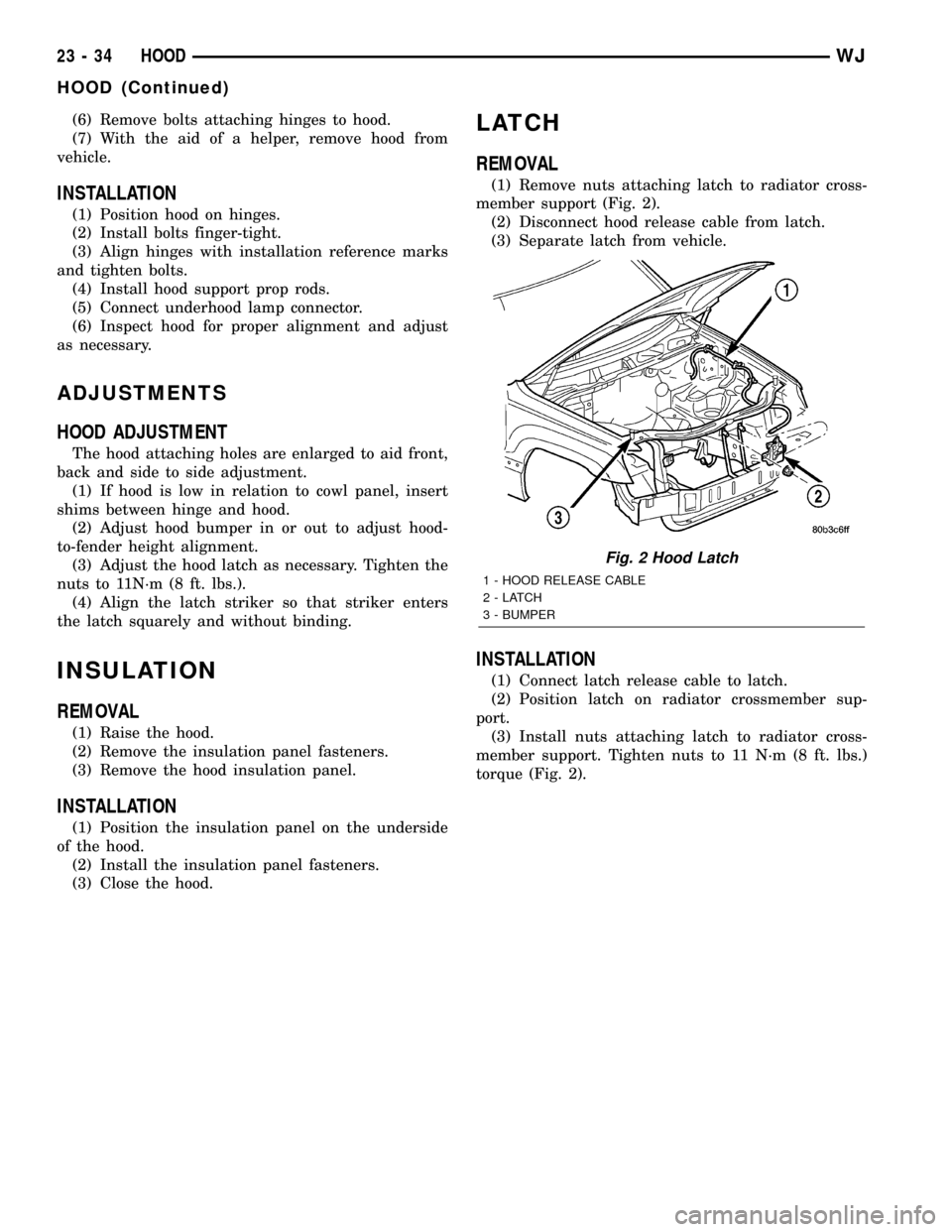
member support (Fig. 2).
(2) Disconnect hood release cable from latch.
(3) Separate latch from vehicle.
INSTALLATION
(1) Connect latch release cable to latch.
(2) Position latch on radiator crossmember sup-
port.
(3) Install nuts attaching latch to radiator cross-
member support. Tighten nuts to 11 N´m (8 ft. lbs.)
torque (Fig. 2).
Fig. 2 Hood Latch
1 - HOOD RELEASE CABLE
2-LATCH
3 - BUMPER
23 - 34 HOODWJ
HOOD (Continued)
Page 1957 of 2199
FRONT HEADREST SLEEVE
REMOVAL
(1) Remove head restraint (Refer to 23 - BODY/
SEATS/FRONT HEADREST - REMOVAL).
(2) Remove seat back cover (Refer to 23 - BODY/
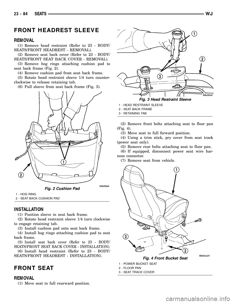
SEATS/FRONT SEAT BACK COVER - REMOVAL).
(3) Remove hog rings attaching cushion pad to
seat back frame (Fig. 2).
(4) Remove cushion pad from seat back frame.
(5) Rotate head restraint sleeve 1/4 turn counter-
clockwise to release retaining tab.
(6) Pull sleeve from seat back frame (Fig. 3).
INSTALLATION
(1) Position sleeve in seat back frame.
(2) Rotate head restraint sleeve 1/4 turn clockwise
to engage retaining tab.
(3) Install cushion pad onto seat back frame.
(4) Install hog rings attaching cushion pad to seat
back frame.
(5)
Install seat back cover (Refer to 23 - BODY/
SEATS/FRONT SEAT BACK COVER - INSTALLATION).
(6) Install head restraint (Refer to 23 - BODY/
SEATS/FRONT HEADREST - INSTALLATION).
FRONT SEAT
REMOVAL
(1) Move seat to full rearward position.(2) Remove front bolts attaching seat to floor pan
(Fig. 4).
(3) Move seat to full forward position.
(4) Using a trim stick, pry cover from seat track
(power seat only).
(5) Remove rear bolts attaching seat to floor pan.
(6) If equipped, disconnect power seat wire har-
ness connector.
(7) Remove seat from vehicle.
Fig. 2 Cushion Pad
1 - HOG RING
2 - SEAT BACK CUSHION PAD
Fig. 3 Head Restraint Sleeve
1 - HEAD RESTRAINT SLEEVE
2 - SEAT BACK FRAME
3 - RETAINING TAB
Fig. 4 Front Bucket Seat
1 - POWER BUCKET SEAT
2 - FLOOR PAN
3 - SEAT TRACK COVER
23 - 84 SEATSWJ
Page 1958 of 2199
INSTALLATION
(1) Position seat on floor pan.
(2) If equipped, connect power seat wire harness
connector.
(3) Install rear bolts attaching seat to floor pan.
Tighten bolts to 40 N´m (30 ft. lbs.) torque.
(4) If equipped, install cover on seat track.
(5) Move seat to full rearward position.
(6) Install front bolts attaching seat to floor pan.
Tighten bolts to 40 N´m (30 ft. lbs.) torque.
FRONT SEAT BACK
REMOVAL
(1) Move seat to full rearward position.
(2) Remove inboard bolt attaching seat back frame
to seat cushion frame.
(3) Move seat to full forward position.
(4) Move seat back to full recline position.
(5) Remove screws attaching seat side shield to
seat frame.
(6) Disconnect wire harness connector from
recliner motor, if equipped.
(7) From the underside of the seat, disconnect the
wire harness connector for the power lumber and/or
heated seat, if equipped.
(8) Remove outboard bolts attaching recliner to
seat cushion frame.
(9) Route the power lumber and/or heated seat
harness through the seat cushion cover, if equipped.
(10) Separate seat back from seat cushion.
INSTALLATION
(1) Position seat back on seat cushion.
(2) Route the power lumber and heater harness
through the seat cushion cover, if equipped.
(3) Install recliner bolts attaching seat back frame
to seat cushion frame. Tighten bolts to 28 N´m (20 ft.
lbs.) torque.
(4) Install the inboard bolt attaching seat back
frame to seat cushion frame. Tighten bolt to 47N´m
(35 ft.lbs.).
(5) Connect wire harness connector to recliner
motor and/or heated seat, if equipped.
(6) From the underside of the seat, connect the
power lumber and/or heated seat wire harness con-
nector to the seat harness, if equipped.
(7) Install screws attaching seat side shield to seat
frame.
FRONT SEAT BACK COVER
REMOVAL
(1) Remove head restraint (Refer to 23 - BODY/
SEATS/FRONT HEADREST - REMOVAL).
(2) Using a trim stick, carefully pry head restraint
release button caps from the top of seat back.
(3) Remove seat back (Refer to 23 - BODY/SEATS/
FRONT SEAT BACK - REMOVAL).
(4) Disengage J-strap at base of seat back.
(5) Slide hand between the face of the seat back
pad and the cushion cover and carefully separate
hook and loop fastener (Fig. 5).
(6) Roll cover upward and disengage hog rings.
(7) Roll cover upward to top of seat back.
(8) Separate cover from seat back.
INSTALLATION
(1) Position cover inside-out at the top of seat
back.
(2) Roll cover downward.
(3) Engage hog rings.
(4) Align seat back cover with hook and loop fas-
teners and secure.
(5) Roll cover downward.
(6) Engage J-strap at base of seat back.
(7) Install seat back (Refer to 23 - BODY/SEATS/
FRONT SEAT BACK - INSTALLATION).
NOTE: The taller head restraint release button cap
is positioned on the left hand side and the head
restraint button cap with the hidden button is posi-
tioned on the right hand side.
Fig. 5 Seat Back Cover
1 - SEAT BACK COVER
2 - HOOK AND LOOP FASTENER
3 - SEAT BACK PAD
WJSEATS 23 - 85
FRONT SEAT (Continued)
Page 1959 of 2199
(8) Position head restraint release button caps on
head restraint sleeves and press to secure.
(9) Install head restraint (Refer to 23 - BODY/
SEATS/FRONT HEADREST - INSTALLATION).
FRONT SEAT CUSHION/COVER
REMOVAL
(1) Remove seat from vehicle (Refer to 23 - BODY/
SEATS/FRONT SEAT - REMOVAL).
(2) Remove seat back (Refer to 23 - BODY/SEATS/
FRONT SEAT BACK - REMOVAL).
(3) Disengage J-straps attaching cushion cover to
seat cushion frame.
(4) Disengage hog rings attaching cushion cover to
cushion frame at rear of seat along bottom of cushion
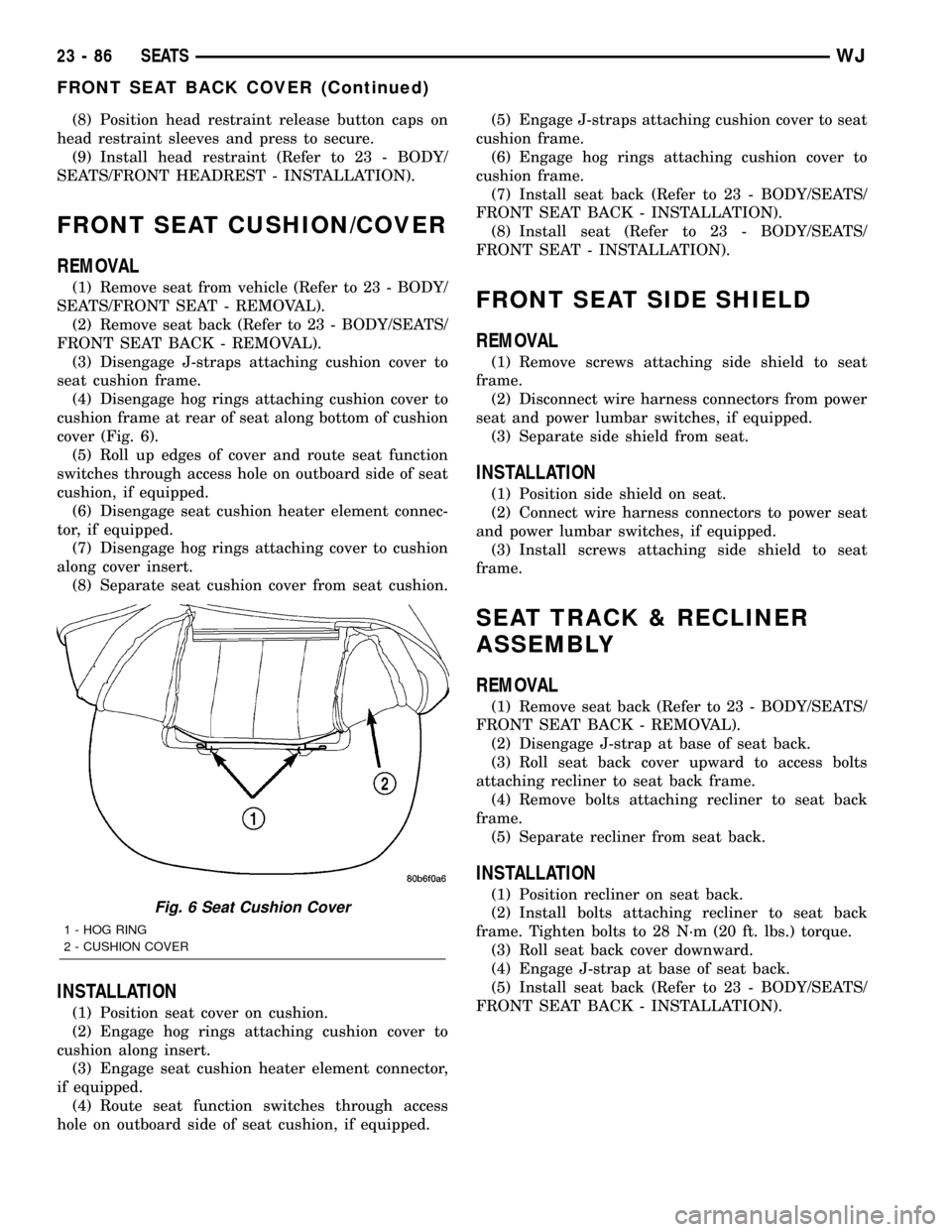
cover (Fig. 6).
(5) Roll up edges of cover and route seat function
switches through access hole on outboard side of seat
cushion, if equipped.
(6) Disengage seat cushion heater element connec-
tor, if equipped.
(7) Disengage hog rings attaching cover to cushion
along cover insert.
(8) Separate seat cushion cover from seat cushion.
INSTALLATION
(1) Position seat cover on cushion.
(2) Engage hog rings attaching cushion cover to
cushion along insert.
(3) Engage seat cushion heater element connector,
if equipped.
(4) Route seat function switches through access
hole on outboard side of seat cushion, if equipped.(5) Engage J-straps attaching cushion cover to seat
cushion frame.
(6) Engage hog rings attaching cushion cover to
cushion frame.
(7) Install seat back (Refer to 23 - BODY/SEATS/
FRONT SEAT BACK - INSTALLATION).
(8) Install seat (Refer to 23 - BODY/SEATS/
FRONT SEAT - INSTALLATION).
FRONT SEAT SIDE SHIELD
REMOVAL
(1) Remove screws attaching side shield to seat
frame.
(2) Disconnect wire harness connectors from power
seat and power lumbar switches, if equipped.
(3) Separate side shield from seat.
INSTALLATION
(1) Position side shield on seat.
(2) Connect wire harness connectors to power seat
and power lumbar switches, if equipped.
(3) Install screws attaching side shield to seat
frame.
SEAT TRACK & RECLINER
ASSEMBLY
REMOVAL
(1) Remove seat back (Refer to 23 - BODY/SEATS/
FRONT SEAT BACK - REMOVAL).
(2) Disengage J-strap at base of seat back.
(3) Roll seat back cover upward to access bolts
attaching recliner to seat back frame.
(4) Remove bolts attaching recliner to seat back
frame.
(5) Separate recliner from seat back.
INSTALLATION
(1) Position recliner on seat back.
(2) Install bolts attaching recliner to seat back
frame. Tighten bolts to 28 N´m (20 ft. lbs.) torque.
(3) Roll seat back cover downward.
(4) Engage J-strap at base of seat back.
(5) Install seat back (Refer to 23 - BODY/SEATS/
FRONT SEAT BACK - INSTALLATION).Fig. 6 Seat Cushion Cover
1 - HOG RING
2 - CUSHION COVER
23 - 86 SEATSWJ
FRONT SEAT BACK COVER (Continued)
Page 1962 of 2199
REAR HEADREST SLEEVE
REMOVAL
(1) Remove seat back (Refer to 23 - BODY/SEATS/
REAR SEAT BACK - REMOVAL).
(2) Remove head rest (Refer to 23 - BODY/SEATS/
REAR HEADREST - REMOVAL).
(3) Remove head rest caps.
(4) Remove seat back cover (Refer to 23 - BODY/
SEATS/REAR SEAT BACK COVER - REMOVAL).
(5) Rotate head rest sleeve 1/4 turn counter-clock-
wise to release retaining tab.
(6) Pull sleeve from seat back frame.
INSTALLATION
(1) Position sleeve in seat back frame.
(2) Rotate head rest sleeve 1/4 turn clockwise to
engage retaining tab.
(3) Install seat back cover (Refer to 23 - BODY/
SEATS/REAR SEAT BACK COVER - INSTALLA-
TION).
(4) Install head rest caps.
NOTE: The head rest cap with the taller button is
always on the inboard side of the seat back.
(5) Install the head rest (Refer to 23 - BODY/
SEATS/REAR HEADREST - INSTALLATION).
NOTE: The folding head rest release knob is always
on the outboard side.
(6) Install the seat back (Refer to 23 - BODY/
SEATS/REAR SEAT BACK - INSTALLATION).
REAR SEAT BACK
REMOVAL
(1) Move rear seat cushions to forward cargo posi-
tion.
(2) Remove bolts attaching seatback side support
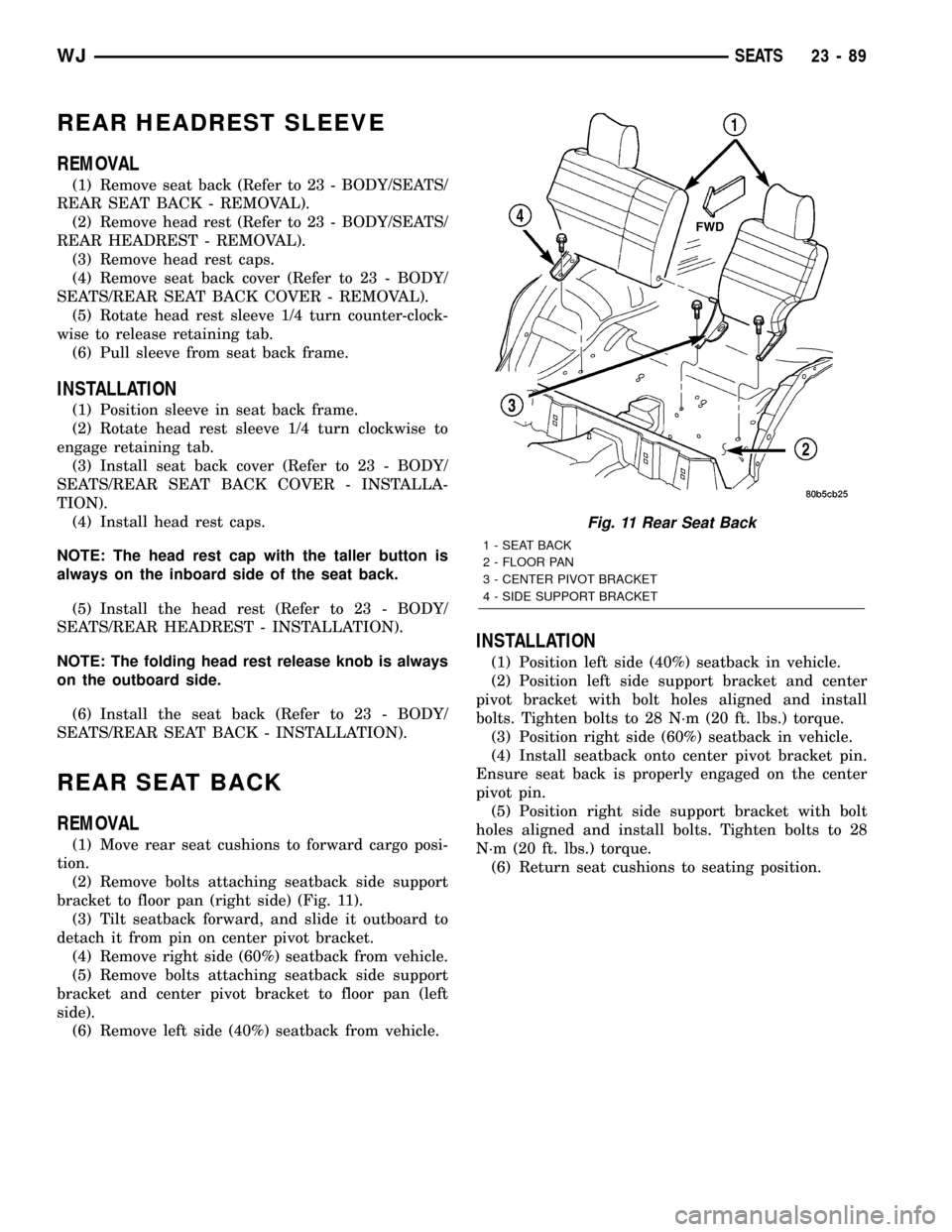
bracket to floor pan (right side) (Fig. 11).
(3) Tilt seatback forward, and slide it outboard to
detach it from pin on center pivot bracket.
(4) Remove right side (60%) seatback from vehicle.
(5) Remove bolts attaching seatback side support
bracket and center pivot bracket to floor pan (left
side).
(6) Remove left side (40%) seatback from vehicle.
INSTALLATION
(1) Position left side (40%) seatback in vehicle.
(2) Position left side support bracket and center
pivot bracket with bolt holes aligned and install
bolts. Tighten bolts to 28 N´m (20 ft. lbs.) torque.
(3) Position right side (60%) seatback in vehicle.
(4) Install seatback onto center pivot bracket pin.
Ensure seat back is properly engaged on the center
pivot pin.
(5) Position right side support bracket with bolt
holes aligned and install bolts. Tighten bolts to 28
N´m (20 ft. lbs.) torque.
(6) Return seat cushions to seating position.
Fig. 11 Rear Seat Back
1 - SEAT BACK
2 - FLOOR PAN
3 - CENTER PIVOT BRACKET
4 - SIDE SUPPORT BRACKET
WJSEATS 23 - 89
Page 1963 of 2199
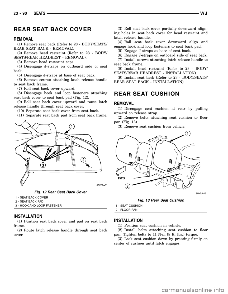
REAR SEAT BACK COVER
REMOVAL
(1) Remove seat back (Refer to 23 - BODY/SEATS/
REAR SEAT BACK - REMOVAL).
(2) Remove head restraint (Refer to 23 - BODY/
SEATS/REAR HEADREST - REMOVAL).
(3) Remove head restraint caps.
(4) Disengage J-straps on outboard side of seat
back.
(5) Disengage J-straps at base of seat back.
(6) Remove screws attaching latch release handle
to seat back frame.
(7) Roll seat back cover upward.
(8) Disengage hook and loop fasteners attaching
seat back cover to seat back pad (Fig. 12).
(9) Roll seat back cover upward and route latch
release handle through seat back cover.
(10) Separate seat back cover from seat back.
(11) Separate seat back pad from seat back frame.
INSTALLATION
(1) Position seat back cover and pad on seat back
frame.
(2) Route latch release handle through seat back
cover.(3) Roll seat back cover partially downward align-
ing holes in seat back cover for head restraint and
latch release handle.
(4) Roll seat back cover downward align and
engage hook and loop fasteners to seat back pad.
(5) Engage J-straps at base of seat back.
(6) Engage J-straps on outboard side of seat back.
(7) Install screws attaching latch release handle to
seat back frame.
(8) Install head restraint (Refer to 23 - BODY/
SEATS/REAR HEADREST - INSTALLATION).
(9) Install seat back (Refer to 23 - BODY/SEATS/
REAR SEAT BACK - INSTALLATION).
REAR SEAT CUSHION
REMOVAL
(1) Disengage seat cushion at rear by pulling
upward on release strap.
(2) Remove bolts attaching seat cushion to floor
pan (Fig. 13).
(3) Remove seat cushion from vehicle.
INSTALLATION
(1) Position seat cushion in vehicle.
(2) Install bolts attaching seat cushion to floor
pan. Tighten bolts to 11 N´m (8 ft. lbs.) torque.
(3) Lock seat cushion down by pressing firmly on
center of cushion until latch engages.
Fig. 12 Rear Seat Back Cover
1 - SEAT BACK COVER
2 - SEAT BACK PAD
3 - HOOK AND LOOP FASTENERFig. 13 Rear Seat Cushion
1 - SEAT CUSHION
2 - FLOOR PAN
23 - 90 SEATSWJ
Page 1965 of 2199
INSTALLATION
(1) Route cable end into latch release handle.
(2) Rotate cable end until barrel end aligns with
key hole slot in latch release handle and insert into
handle.
(3) Engage retainers securing latch release cable
housing to latch release handle.
(4) Position latch release handle in seat back.
Ensure seat back cover is properly aligned.
(5) Install screws attaching release handle to seat
back frame.
FOLDING REAR SEAT BACK
LATCH/HINGE
REMOVAL
(1) Remove seat back (Refer to 23 - BODY/SEATS/
REAR SEAT BACK - REMOVAL).
(2) Disengage J-straps on outboard side of seat
back.
(3) Disengage release cable from latch.
(4) Remove bolts attaching latch/hinge to seat back
frame.
(5) Separate latch/hinge from seat back frame.
INSTALLATION
(1) Position latch/hinge on seat back frame.
(2) Install bolts attaching latch/hinge to seat back
frame. Tighten bolts to 28 N´m (20 ft. lbs.) torque.
(3) Engage latch release cable.
(4) Engage J-straps on outboard side of seat back.
(5) Install seat back (Refer to 23 - BODY/SEATS/
REAR SEAT BACK - INSTALLATION).
23 - 92 SEATSWJ
FOLDING REAR SEAT BACK LATCH HANDLE (Continued)