Fan JEEP GRAND CHEROKEE 2003 WJ / 2.G Owner's Guide
[x] Cancel search | Manufacturer: JEEP, Model Year: 2003, Model line: GRAND CHEROKEE, Model: JEEP GRAND CHEROKEE 2003 WJ / 2.GPages: 2199, PDF Size: 76.01 MB
Page 358 of 2199
GENERATOR
DESCRIPTION
The generator is belt-driven by the engine using a
serpentine type drive belt. It is serviced only as a
complete assembly. If the generator fails for any rea-
son, the entire assembly must be replaced.
OPERATION
As the energized rotor begins to rotate within the
generator, the spinning magnetic field induces a cur-
rent into the windings of the stator coil. Once the
generator begins producing sufficient current, it also
provides the current needed to energize the rotor.
The Y type stator winding connections deliver the
induced AC current to 3 positive and 3 negative
diodes for rectification. From the diodes, rectified DC
current is delivered to the vehicle electrical system
through the generator battery terminal.
Although the generators appear the same exter-
nally, different generators with different output rat-
ings are used on this vehicle. Be certain that the
replacement generator has the same output rating
and part number as the original unit. Refer to Gen-
erator Ratings in the Specifications section at the
back of this group for amperage ratings and part
numbers.
Noise emitting from the generator may be caused
by: worn, loose or defective bearings; a loose or defec-
tive drive pulley; incorrect, worn, damaged or misad-
justed fan drive belt; loose mounting bolts; a
misaligned drive pulley or a defective stator or diode.
REMOVAL
WARNING: DISCONNECT NEGATIVE CABLE FROM
BATTERY BEFORE REMOVING BATTERY OUTPUT
WIRE (B+ WIRE) FROM GENERATOR. FAILURE TO
DO SO CAN RESULT IN INJURY OR DAMAGE TO
ELECTRICAL SYSTEM.
(1) Disconnect negative battery cable at battery.
(2) Remove generator drive belt. Refer to Cooling
System for procedure.
(3) Unsnap cable protector cover from B+ mount-
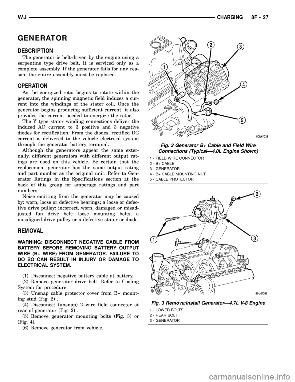
ing stud (Fig. 2) .
(4) Disconnect (unsnap) 2±wire field connector at
rear of generator (Fig. 2) .
(5) Remove generator mounting bolts (Fig. 3) or
(Fig. 4).
(6) Remove generator from vehicle.
Fig. 2 Generator B+ Cable and Field Wire
Connections (TypicalÐ4.0L Engine Shown)
1 - FIELD WIRE CONNECTOR
2 - B+ CABLE
3 - GENERATOR
4 - B+ CABLE MOUNTING NUT
5 - CABLE PROTECTOR
Fig. 3 Remove/Install GeneratorÐ4.7L V-8 Engine
1 - LOWER BOLTS
2 - REAR BOLT
3 - GENERATOR
WJCHARGING 8F - 27
Page 405 of 2199
INSTALLATION
INSTALLATION - 4.0L
SENSOR ONLY - 4.0L
The Camshaft Position Sensor (CMP) on the 4.0L
6±cylinder engine is bolted to the top of the oil pump
drive shaft assembly (Fig. 6). The sensor and drive
shaft assembly is located on the right side of the
engine near the oil filter (Fig. 7).
(1) Install sensor to oil pump drive.
(2) Install 2 sensor mounting bolts and tighten to
2 N´m (15 in. lbs.) torque.
(3) Connect electrical connector to CMP sensor.
OIL PUMP DRIVE AND SENSOR - 4.0L
(1) Clean oil pump drive mounting hole area of
engine block.
(2) Install new oil pump drive-to-engine block gas-
ket.
(3) Temporarily install a toothpick or similar tool
through access hole at side of oil pump drive housing.
Align toothpick into mating hole on pulse ring (Fig.
8).(4) Install oil pump drive into engine while align-
ing into slot on oil pump. Rotate oil pump drive back
to its original position and install hold-down clamp
and bolt. Finger tighten bolt. Do not do a final tight-
ening of bolt at this time.
(5) If engine crankshaft or camshaft has been
rotated, such as during engine tear-down, CMP sen-
sor relationship must be reestablished.
(a) Remove ignition coil rail assembly. Refer to
Ignition Coil Removal/Installation.
(b) Remove cylinder number 1 spark plug.
(c) Hold a finger over the open spark plug hole.
Rotate engine at vibration dampener bolt until
compression (pressure) is felt.
(d) Slowly continue to rotate engine. Do this
until timing index mark on vibration damper pul-
ley aligns with top dead center (TDC) mark (0
degree) on timing degree scale (Fig. 9). Always
rotate engine in direction of normal rotation. Do
not rotate engine backward to align timing marks.
(e) Install oil pump drive into engine while
aligning into slot on oil pump. If pump drive will
not drop down flush to engine block, the oil pump
slot is not aligned. Remove oil pump drive and
align slot in oil pump to shaft at bottom of drive.
Install into engine. Rotate oil pump drive back to
its original position and install hold-down clamp
and bolt. Finger tighten bolt. Do not do a final
tightening of bolt at this time.
(f) Remove toothpick from housing.
(6) Install sensor to oil pump drive. After installa-
tion, the CMP sensor should face rear of engine 0É.
(7) Install 2 sensor mounting bolts and tighten to
2 N´m (15 in. lbs.) torque.
(8) Connect electrical connector to CMP sensor.
(9) If removed, install spark plug and ignition coil
rail.
To verify correct rotational position of oil pump
drive, the DRB scan tool must be used.
WARNING: WHEN PERFORMING THE FOLLOWING
TEST, THE ENGINE WILL BE RUNNING. BE CARE-
FUL NOT TO STAND IN LINE WITH THE FAN
BLADES OR FAN BELT. DO NOT WEAR LOOSE
CLOTHING.
(10) Connect DRB scan tool to data link connector.
The data link connector is located in passenger com-
partment, below and to left of steering column.
(11) Gain access to SET SYNC screen on DRB.
(12) Follow directions on DRB screen and start
engine. Bring to operating temperature (engine must
be in ªclosed loopº mode).
(13) With engine running atidle speed, the words
IN RANGE should appear on screen along with 0É.
This indicates correct position of oil pump drive.
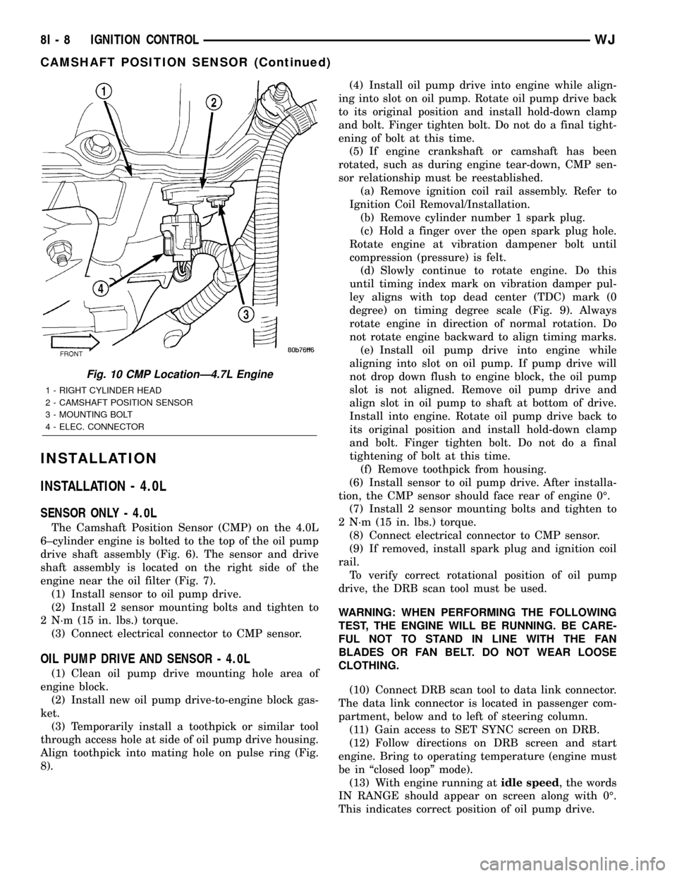
Fig. 10 CMP LocationÐ4.7L Engine
1 - RIGHT CYLINDER HEAD
2 - CAMSHAFT POSITION SENSOR
3 - MOUNTING BOLT
4 - ELEC. CONNECTOR
8I - 8 IGNITION CONTROLWJ
CAMSHAFT POSITION SENSOR (Continued)
Page 590 of 2199
INSTALLATION
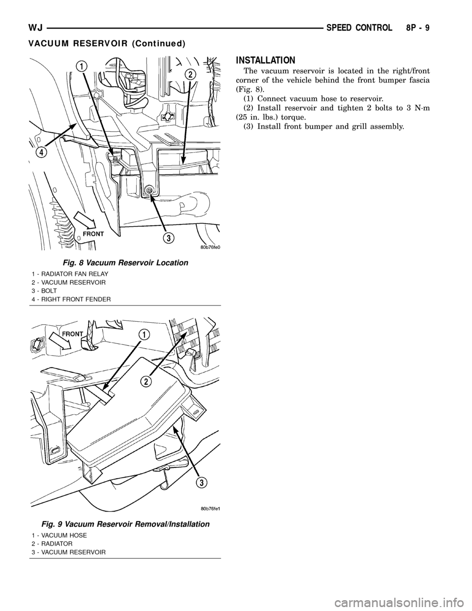
The vacuum reservoir is located in the right/front
corner of the vehicle behind the front bumper fascia
(Fig. 8).
(1) Connect vacuum hose to reservoir.
(2) Install reservoir and tighten 2 bolts to 3 N´m
(25 in. lbs.) torque.
(3) Install front bumper and grill assembly.
Fig. 8 Vacuum Reservoir Location
1 - RADIATOR FAN RELAY
2 - VACUUM RESERVOIR
3 - BOLT
4 - RIGHT FRONT FENDER
Fig. 9 Vacuum Reservoir Removal/Installation
1 - VACUUM HOSE
2 - RADIATOR
3 - VACUUM RESERVOIR
WJSPEED CONTROL 8P - 9
VACUUM RESERVOIR (Continued)
Page 662 of 2199

DESCRIPTION - CONNECTOR, GROUND AND
SPLICE INFORMATION
CAUTION: Not all connectors are serviced. Some
connectors are serviced only with a harness. A typ-
ical example might be the Supplemental Restraint
System connectors. Always check parts availability
before attempting a repair.
IDENTIFICATION
In-line connectors are identified by a number, as
follows:
²In-line connectors located in the engine compart-
ment are C100 series numbers
²In-line connectors located in the Instrument
Panel area are C200 series numbers.
²In-line connectors located in the body are C300
series numbers.
²Jumper harness connectors are C400 series
numbers.
²Grounds and ground connectors are identified
with a ªGº and follow the same series numbering as
the in-line connectors.
²Splices are identified with an ªSº and follow the
same series numbering as the in-line connectors.
²Component connectors are identified by the com-
ponent name instead of a number. Multiple connec-
tors on a component use a C1, C2, etc. identifier.
LOCATIONS
Section 8W-91 contains connector/ground/splice
location illustrations. The illustrations contain the
connector name (or number)/ground number/splice
number and component identification. Connector/
ground/splice location charts in section 8W-91 refer-
ence the figure numbers of the illustrations.
The abbreviation T/O is used in the component
location section to indicate a point in which the wir-
ing harness branches out to a component. The abbre-
viation N/S means Not Shown in the illustrations
WARNING
WARNINGS - GENERAL
WARNINGSprovide information to prevent per-
sonal injury and vehicle damage. Below is a list of
general warnings that should be followed any time a
vehicle is being serviced.
WARNING: ALWAYS WEAR SAFETY GLASSES FOR
EYE PROTECTION.
WARNING: USE SAFETY STANDS ANYTIME A PRO-
CEDURE REQUIRES BEING UNDER A VEHICLE.WARNING: BE SURE THAT THE IGNITION SWITCH
ALWAYS IS IN THE OFF POSITION, UNLESS THE
PROCEDURE REQUIRES IT TO BE ON.
WARNING: SET THE PARKING BRAKE WHEN
WORKING ON ANY VEHICLE. AN AUTOMATIC
TRANSMISSION SHOULD BE IN PARK. A MANUAL
TRANSMISSION SHOULD BE IN NEUTRAL.
WARNING: OPERATE THE ENGINE ONLY IN A
WELL-VENTILATED AREA.
WARNING: KEEP AWAY FROM MOVING PARTS
WHEN THE ENGINE IS RUNNING, ESPECIALLY THE
FAN AND BELTS.
WARNING: TO PREVENT SERIOUS BURNS, AVOID
CONTACT WITH HOT PARTS SUCH AS THE RADIA-
TOR, EXHAUST MANIFOLD(S), TAIL PIPE, CATA-
LYTIC CONVERTER AND MUFFLER.
WARNING: DO NOT ALLOW FLAME OR SPARKS
NEAR THE BATTERY. GASES ARE ALWAYS
PRESENT IN AND AROUND THE BATTERY.
WARNING: ALWAYS REMOVE RINGS, WATCHES,
LOOSE HANGING JEWELRY AND AVOID LOOSE
CLOTHING.
DIAGNOSIS AND TESTING - WIRING HARNESS
TROUBLESHOOTING TOOLS
When diagnosing a problem in an electrical circuit
there are several common tools necessary. These tools
are listed and explained below.
²Jumper Wire - This is a test wire used to con-
nect two points of a circuit. It can be used to bypass
an open in a circuit.
WARNING: NEVER USE A JUMPER WIRE ACROSS
A LOAD, SUCH AS A MOTOR, CONNECTED
BETWEEN A BATTERY FEED AND GROUND.
²Voltmeter - Used to check for voltage on a cir-
cuit. Always connect the black lead to a known good
ground and the red lead to the positive side of the
circuit.
CAUTION: Most of the electrical components used
in today's vehicles are Solid State. When checking
voltages in these circuits, use a meter with a 10 -
megohm or greater impedance rating.
WJ8W-01 WIRING DIAGRAM INFORMATION 8W - 01 - 7
WIRING DIAGRAM INFORMATION (Continued)
Page 1051 of 2199

Component Page
LIFTGATE FLIP-UP PUSH
BUTTON SWITCH................ 8W-80-97
LIFTGATE FLIP-UP RELEASE
SOLENOID...................... 8W-80-97
LIFTGATE POWER LOCK MOTOR..... 8W-80-97
LINE PRESSURE SENSOR (4.7L)...... 8W-80-98
MANIFOLD ABSOLUTE PRESSURE
SENSOR (4.0L)................... 8W-80-98
MANIFOLD ABSOLUTE PRESSURE
SENSOR (4.7L)................... 8W-80-98
MANUAL TEMPERATURE
CONTROL C1 (MTC).............. 8W-80-98
MANUAL TEMPERATURE
CONTROL C2 (MTC).............. 8W-80-99
MASS AIR FLOW SENSOR (DIESEL) . . . 8W-80-99
MODE DOOR MOTOR/ACTUATOR
(AZC).......................... 8W-80-99
NEEDLE MOVEMENT SENSOR
(DIESEL)....................... 8W-80-99
OUTPUT SPEED SENSOR (4.0L)...... 8W-80-99
OUTPUT SPEED SENSOR (4.7L)..... 8W-80-100
OVERHEAD MAP/COURTESY LAMP . . 8W-80-100
OXYGEN SENSOR 1/1 UPSTREAM.... 8W-80-100
OXYGEN SENSOR 1/2 DOWNSTREAM . 8W-80-100
OXYGEN SENSOR 2/1 UPSTREAM.... 8W-80-100
OXYGEN SENSOR 2/2
DOWNSTREAM................. 8W-80-101
PARK/NEUTRAL POSITION SWITCH
(4.0L).......................... 8W-80-101
PARK/NEUTRAL POSITION SWITCH
(DIESEL)...................... 8W-80-101
PASSENGER AIRBAG.............. 8W-80-101
PASSENGER BLEND DOOR
MOTOR/ACTUATOR (LHD) (AZC) . . . 8W-80-101
PASSENGER BLEND DOOR
MOTOR/ACTUATOR (RHD) (AZC) . . . 8W-80-102
PASSENGER CURTAIN AIRBAG...... 8W-80-102
PASSENGER DOOR LOCK MOTOR/AJAR
SWITCH....................... 8W-80-102
PASSENGER DOOR MODULE C1..... 8W-80-102
PASSENGER DOOR MODULE C2..... 8W-80-103
PASSENGER FRONT DOOR
COURTESY LAMP............... 8W-80-103
PASSENGER FRONT POWER
WINDOW MOTOR............... 8W-80-103
PASSENGER HEATED SEAT BACK
(PREMIUM I/III)................. 8W-80-103
PASSENGER HEATED SEAT CUSHION
(PREMIUM I/III)................. 8W-80-104
PASSENGER HEATED SEAT SWITCH . 8W-80-104
PASSENGER LUMBAR MOTOR
(MIDLINE/PREMIUM)............ 8W-80-104
PASSENGER LUMBAR SWITCH
(MIDLINE/PREMIUM)............ 8W-80-104
PASSENGER POWER MIRROR....... 8W-80-105Component Page
PASSENGER POWER SEAT FRONT
RISER MOTOR.................. 8W-80-105
PASSENGER POWER SEAT
HORIZONTAL MOTOR........... 8W-80-105
PASSENGER POWER SEAT REAR
RISER MOTOR.................. 8W-80-105
PASSENGER POWER SEAT RECLINER
MOTOR (MIDLINE/PREMIUM)..... 8W-80-106
PASSENGER POWER SEAT SWITCH
(MIDLINE/PREMIUM)............ 8W-80-106
PASSENGER REAR POWER
WINDOW MOTOR............... 8W-80-106
PASSENGER REAR POWER
WINDOW SWITCH............... 8W-80-106
PASSENGER SEAT BELT SWITCH.... 8W-80-106
PASSENGER SIDE IMPACT
SENSOR....................... 8W-80-107
POWER AMPLIFIER C1
(PREMIUM RADIO).............. 8W-80-107
POWER AMPLIFIER C2
(PREMIUM RADIO).............. 8W-80-107
POWER CONNECTOR.............. 8W-80-108
POWERTRAIN CONTROL
MODULE C1 (GAS).............. 8W-80-108
POWERTRAIN CONTROL
MODULE C2 (GAS).............. 8W-80-109
POWERTRAIN CONTROL
MODULE C3 (GAS).............. 8W-80-110
RADIATOR FAN MOTOR............ 8W-80-110
RADIATOR FAN RELAY............. 8W-80-111
RADIO C1........................ 8W-80-111
RADIO C2........................ 8W-80-111
RAIN SENSOR (AUTOWIPE)......... 8W-80-112
REAR POWER OUTLET............. 8W-80-112
REAR WASHER PUMP.............. 8W-80-112
REAR WIPER MOTOR.............. 8W-80-112
RECIRCULATION DOOR
MOTOR/ACTUATOR (AZC)......... 8W-80-112
RED BRAKE WARNING INDICATOR
SWITCH....................... 8W-80-113
REMOTE KEYLESS MODULE
(JAPAN)....................... 8W-80-113
RIGHT COURTESY LAMP........... 8W-80-113
RIGHT DOOR HANDLE
COURTESY LAMP............... 8W-80-113
RIGHT FOG LAMP................. 8W-80-113
RIGHT FRONT DOOR SPEAKER..... 8W-80-114
RIGHT FRONT IMPACT SENSOR..... 8W-80-114
RIGHT FRONT PARK LAMP......... 8W-80-114
RIGHT FRONT PARK/TURN SIGNAL LAMP
(EXCEPT BUILT-UP-EXPORT)...... 8W-80-114
RIGHT FRONT SIDE MARKER LAMP
(EXCEPT BUILT-UP-EXPORT)...... 8W-80-115
RIGHT FRONT TURN SIGNAL LAMP
(BUILT-UP-EXPORT)............. 8W-80-115
8W - 80 - 4 8W-80 CONNECTOR PIN-OUTWJ
Page 1123 of 2199
ENGINE CONTROL MODULE C1 (DIESEL) - BLACK 81 WAY
CAV CIRCUIT FUNCTION
55 B22 20DG/YL VEHICLE SPEED SENSOR SIGNAL
56 K225 18BK ACCELERATOR PEDAL POSITION SENSOR 2 GROUND
57 - -
58 K4 20BK/LB WATER IN FUEL SENSOR GROUND
59 K900 18GY INTAKE PORT SWIRL ACTUATOR SIGNAL
60 K7 20RD/WT FUEL PRESSURE SENSOR 5 VOLT SUPPLY
61 K51 20DB/YL AUTO SHUT DOWN RELAY CONTROL
62 - -
63 - -
64 - -
65 - -
66 - -
67 K173 20GY HYDRAULIC RADIATOR FAN SOLENOID CONTROL
68 - -
69 C13 20DB/RD A/C COMPRESSOR CLUTCH RELAY CONTROL
70 - -
71 - -
72 K236 20GY/PK GLOW PLUG RELAY NO. 2 CONTROL
73 - -
74 T752 20DG/RD ENGINE STARTER MOTOR RELAY CONTROL
75 K132 20BR/BK VISCOUS/CABIN HEATER RELAY CONTROL
76 Y42 20BR/BK WASTEGATE SOLENOID CONTROL
77 K152 20WT GLOW PLUG RELAY NO. 1 CONTROL
78 - -
79 - -
80 K46 20DB/BK FUEL PRESSURE SOLENOID CONTROL
81 K46 20DB/BK FUEL PRESSURE SOLENOID CONTROL
ENGINE CONTROL MODULE C2 (DIESEL) - BLACK 40 WAY
CAV CIRCUIT FUNCTION
82 D21 20PK SCI TRANSMIT
83 - -
84 - -
85 - -
86 - -
87 - -
88 - -
89 K35 20GY/YL EGR SOLENOID CONTROL
90 - -
91 - -
92 - -
93 - -
94 G123 20DG/WT WATER IN FUEL SENSOR SIGNAL
95 - -
96 - -
97 - -
98 - -
99 - -
100 - -
101 - -
102 - -
103 - -
104 - -
8W - 80 - 76 8W-80 CONNECTOR PIN-OUTWJ
Page 1131 of 2199
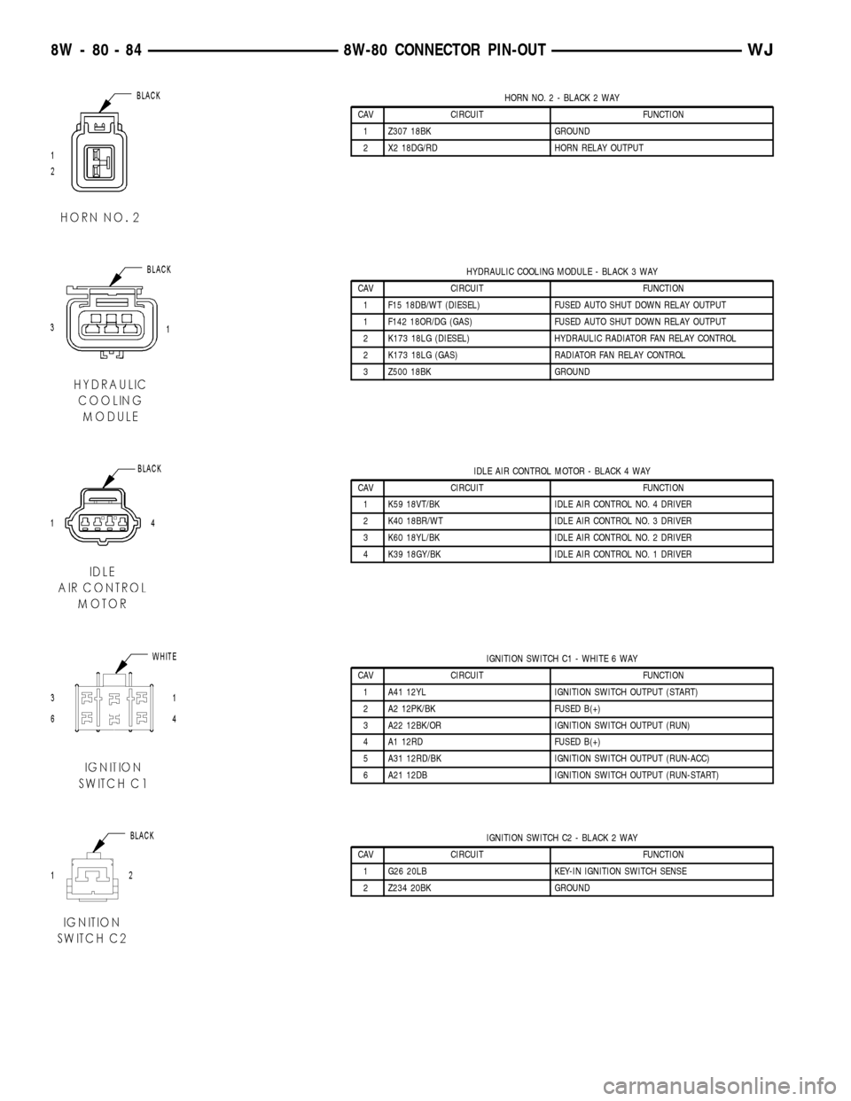
HORN NO. 2 - BLACK 2 WAY
CAV CIRCUIT FUNCTION
1 Z307 18BK GROUND
2 X2 18DG/RD HORN RELAY OUTPUT
HYDRAULIC COOLING MODULE - BLACK 3 WAY
CAV CIRCUIT FUNCTION
1 F15 18DB/WT (DIESEL) FUSED AUTO SHUT DOWN RELAY OUTPUT
1 F142 18OR/DG (GAS) FUSED AUTO SHUT DOWN RELAY OUTPUT
2 K173 18LG (DIESEL) HYDRAULIC RADIATOR FAN RELAY CONTROL
2 K173 18LG (GAS) RADIATOR FAN RELAY CONTROL
3 Z500 18BK GROUND
IDLE AIR CONTROL MOTOR - BLACK 4 WAY
CAV CIRCUIT FUNCTION
1 K59 18VT/BK IDLE AIR CONTROL NO. 4 DRIVER
2 K40 18BR/WT IDLE AIR CONTROL NO. 3 DRIVER
3 K60 18YL/BK IDLE AIR CONTROL NO. 2 DRIVER
4 K39 18GY/BK IDLE AIR CONTROL NO. 1 DRIVER
IGNITION SWITCH C1 - WHITE 6 WAY
CAV CIRCUIT FUNCTION
1 A41 12YL IGNITION SWITCH OUTPUT (START)
2 A2 12PK/BK FUSED B(+)
3 A22 12BK/OR IGNITION SWITCH OUTPUT (RUN)
4 A1 12RD FUSED B(+)
5 A31 12RD/BK IGNITION SWITCH OUTPUT (RUN-ACC)
6 A21 12DB IGNITION SWITCH OUTPUT (RUN-START)
IGNITION SWITCH C2 - BLACK 2 WAY
CAV CIRCUIT FUNCTION
1 G26 20LB KEY-IN IGNITION SWITCH SENSE
2 Z234 20BK GROUND
8W - 80 - 84 8W-80 CONNECTOR PIN-OUTWJ
Page 1156 of 2199
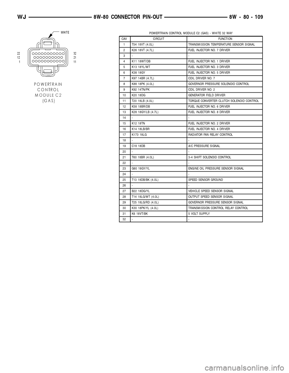
POWERTRAIN CONTROL MODULE C2 (GAS) - WHITE 32 WAY
CAV CIRCUIT FUNCTION
1 T54 18VT (4.0L) TRANSMISSION TEMPERATURE SENSOR SIGNAL
2 K26 18VT (4.7L) FUEL INJECTOR NO. 7 DRIVER
3- -
4 K11 18WT/DB FUEL INJECTOR NO. 1 DRIVER
5 K13 18YL/WT FUEL INJECTOR NO. 3 DRIVER
6 K38 18GY FUEL INJECTOR NO. 5 DRIVER
7 K97 14BR (4.7L) COIL DRIVER NO. 7
8 K88 18PK (4.0L) GOVERNOR PRESSURE SOLENOID CONTROL
9 K92 14TN/PK COIL DRIVER NO. 2
10 K20 18DG GENERATOR FIELD DRIVER
11 T20 18LB (4.0L) TORQUE CONVERTER CLUTCH SOLENOID CONTROL
12 K58 18BR/DB FUEL INJECTOR NO. 6 DRIVER
13 K28 18GY/LB (4.7L) FUEL INJECTOR NO. 8 DRIVER
14 - -
15 K12 18TN FUEL INJECTOR NO. 2 DRIVER
16 K14 18LB/BR FUEL INJECTOR NO. 4 DRIVER
17 K173 18LG RADIATOR FAN RELAY CONTROL
18 - -
19 C18 18DB A/C PRESSURE SIGNAL
20 - -
21 T60 18BR (4.0L) 3-4 SHIFT SOLENOID CONTROL
22 - -
23 G60 18GY/YL ENGINE OIL PRESSURE SENSOR SIGNAL
24 - -
25 T13 18DB/BK (4.0L) SPEED SENSOR GROUND
26 - -
27 B22 18DG/YL VEHICLE SPEED SENSOR SIGNAL
28 T14 18LG/WT (4.0L) OUTPUT SPEED SENSOR SIGNAL
29 T25 18LG/RD (4.0L) GOVERNOR PRESSURE SENSOR SIGNAL
30 K30 18PK/YL (4.0L) TRANSMISSION CONTROL RELAY CONTROL
31 K6 18VT/BK 5 VOLT SUPPLY
32 - -
WJ8W-80 CONNECTOR PIN-OUT 8W - 80 - 109
Page 1157 of 2199
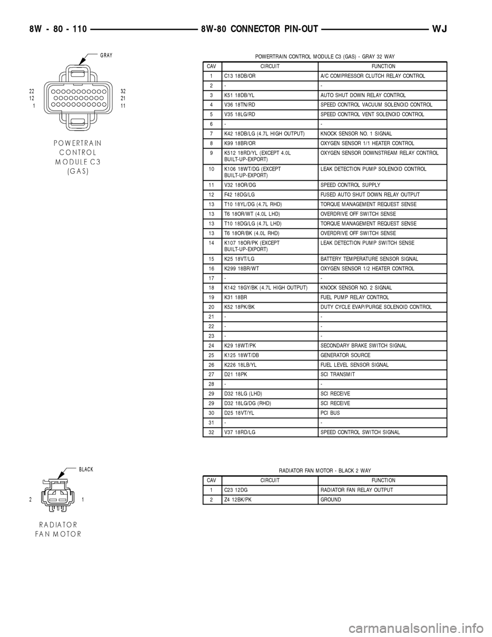
POWERTRAIN CONTROL MODULE C3 (GAS) - GRAY 32 WAY
CAV CIRCUIT FUNCTION
1 C13 18DB/OR A/C COMPRESSOR CLUTCH RELAY CONTROL
2- -
3 K51 18DB/YL AUTO SHUT DOWN RELAY CONTROL
4 V36 18TN/RD SPEED CONTROL VACUUM SOLENOID CONTROL
5 V35 18LG/RD SPEED CONTROL VENT SOLENOID CONTROL
6- -
7 K42 18DB/LG (4.7L HIGH OUTPUT) KNOCK SENSOR NO. 1 SIGNAL
8 K99 18BR/OR OXYGEN SENSOR 1/1 HEATER CONTROL
9 K512 18RD/YL (EXCEPT 4.0L
BUILT-UP-EXPORT)OXYGEN SENSOR DOWNSTREAM RELAY CONTROL
10 K106 18WT/DG (EXCEPT
BUILT-UP-EXPORT)LEAK DETECTION PUMP SOLENOID CONTROL
11 V32 18OR/DG SPEED CONTROL SUPPLY
12 F42 18DG/LG FUSED AUTO SHUT DOWN RELAY OUTPUT
13 T10 18YL/DG (4.7L RHD) TORQUE MANAGEMENT REQUEST SENSE
13 T6 18OR/WT (4.0L LHD) OVERDRIVE OFF SWITCH SENSE
13 T10 18DG/LG (4.7L LHD) TORQUE MANAGEMENT REQUEST SENSE
13 T6 18OR/BK (4.0L RHD) OVERDRIVE OFF SWITCH SENSE
14 K107 18OR/PK (EXCEPT
BUILT-UP-EXPORT)LEAK DETECTION PUMP SWITCH SENSE
15 K25 18VT/LG BATTERY TEMPERATURE SENSOR SIGNAL
16 K299 18BR/WT OXYGEN SENSOR 1/2 HEATER CONTROL
17 - -
18 K142 18GY/BK (4.7L HIGH OUTPUT) KNOCK SENSOR NO. 2 SIGNAL
19 K31 18BR FUEL PUMP RELAY CONTROL
20 K52 18PK/BK DUTY CYCLE EVAP/PURGE SOLENOID CONTROL
21 - -
22 - -
23 - -
24 K29 18WT/PK SECONDARY BRAKE SWITCH SIGNAL
25 K125 18WT/DB GENERATOR SOURCE
26 K226 18LB/YL FUEL LEVEL SENSOR SIGNAL
27 D21 18PK SCI TRANSMIT
28 - -
29 D32 18LG (LHD) SCI RECEIVE
29 D32 18LG/DG (RHD) SCI RECEIVE
30 D25 18VT/YL PCI BUS
31 - -
32 V37 18RD/LG SPEED CONTROL SWITCH SIGNAL
RADIATOR FAN MOTOR - BLACK 2 WAY
CAV CIRCUIT FUNCTION
1 C23 12DG RADIATOR FAN RELAY OUTPUT
2 Z4 12BK/PK GROUND
8W - 80 - 110 8W-80 CONNECTOR PIN-OUTWJ
Page 1158 of 2199
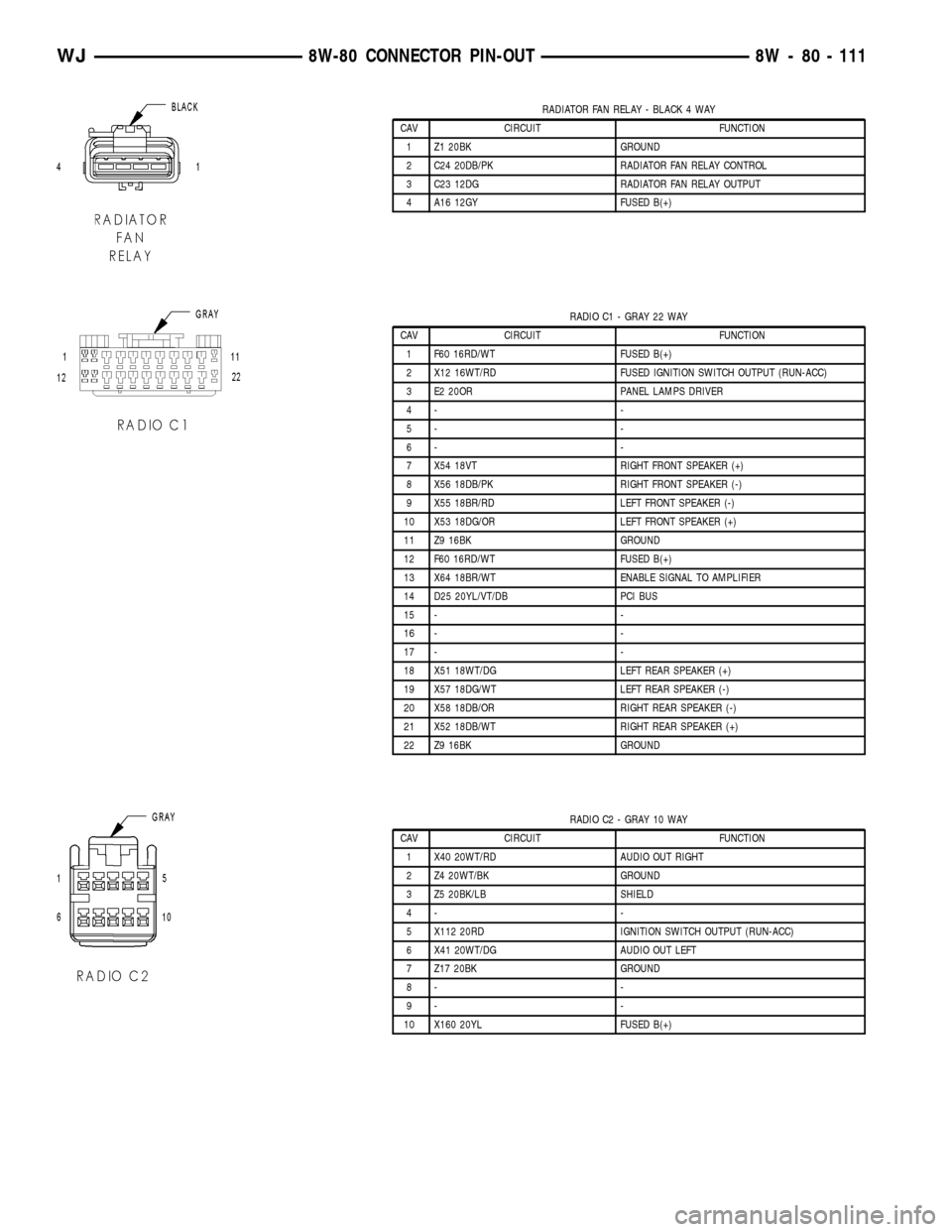
RADIATOR FAN RELAY - BLACK 4 WAY
CAV CIRCUIT FUNCTION
1 Z1 20BK GROUND
2 C24 20DB/PK RADIATOR FAN RELAY CONTROL
3 C23 12DG RADIATOR FAN RELAY OUTPUT
4 A16 12GY FUSED B(+)
RADIO C1 - GRAY 22 WAY
CAV CIRCUIT FUNCTION
1 F60 16RD/WT FUSED B(+)
2 X12 16WT/RD FUSED IGNITION SWITCH OUTPUT (RUN-ACC)
3 E2 20OR PANEL LAMPS DRIVER
4- -
5- -
6- -
7 X54 18VT RIGHT FRONT SPEAKER (+)
8 X56 18DB/PK RIGHT FRONT SPEAKER (-)
9 X55 18BR/RD LEFT FRONT SPEAKER (-)
10 X53 18DG/OR LEFT FRONT SPEAKER (+)
11 Z9 16BK GROUND
12 F60 16RD/WT FUSED B(+)
13 X64 18BR/WT ENABLE SIGNAL TO AMPLIFIER
14 D25 20YL/VT/DB PCI BUS
15 - -
16 - -
17 - -
18 X51 18WT/DG LEFT REAR SPEAKER (+)
19 X57 18DG/WT LEFT REAR SPEAKER (-)
20 X58 18DB/OR RIGHT REAR SPEAKER (-)
21 X52 18DB/WT RIGHT REAR SPEAKER (+)
22 Z9 16BK GROUND
RADIO C2 - GRAY 10 WAY
CAV CIRCUIT FUNCTION
1 X40 20WT/RD AUDIO OUT RIGHT
2 Z4 20WT/BK GROUND
3 Z5 20BK/LB SHIELD
4- -
5 X112 20RD IGNITION SWITCH OUTPUT (RUN-ACC)
6 X41 20WT/DG AUDIO OUT LEFT
7 Z17 20BK GROUND
8- -
9- -
10 X160 20YL FUSED B(+)
WJ8W-80 CONNECTOR PIN-OUT 8W - 80 - 111