Wheel remove JEEP GRAND CHEROKEE 2003 WJ / 2.G Owner's Guide
[x] Cancel search | Manufacturer: JEEP, Model Year: 2003, Model line: GRAND CHEROKEE, Model: JEEP GRAND CHEROKEE 2003 WJ / 2.GPages: 2199, PDF Size: 76.01 MB
Page 156 of 2199
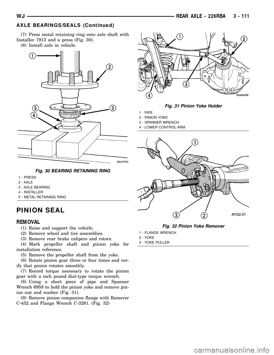
(7) Press metal retaining ring onto axle shaft with
Installer 7913 and a press (Fig. 30).
(8) Install axle in vehicle.
PINION SEAL
REMOVAL
(1) Raise and support the vehicle.
(2) Remove wheel and tire assemblies.
(3) Remove rear brake calipers and rotors.
(4) Mark propeller shaft and pinion yoke for
installation reference.
(5) Remove the propeller shaft from the yoke.
(6) Rotate pinion gear three or four times and ver-
ify that pinion rotates smoothly.
(7) Record torque necessary to rotate the pinion
gear with a inch pound dial-type torque wrench.
(8) Using a short piece of pipe and Spanner
Wrench 6958 to hold the pinion yoke and remove pin-
ion nut and washer (Fig. 31).
(9) Remove pinion companion flange with Remover
C-452 and Flange Wrench C-3281. (Fig. 32)
Fig. 30 BEARING RETAINING RING
1 - PRESS
2 - AXLE
3 - AXLE BEARING
4 - INSTALLER
5 - METAL RETAINING RING
Fig. 31 Pinion Yoke Holder
1 - PIPE
2 - PINION YOKE
3 - SPANNER WRENCH
4 - LOWER CONTROL ARM
Fig. 32 Pinion Yoke Remover
1 - FLANGE WRENCH
2 - YOKE
3 - YOKE PULLER
WJREAR AXLE - 226RBA 3 - 111
AXLE BEARINGS/SEALS (Continued)
Page 158 of 2199
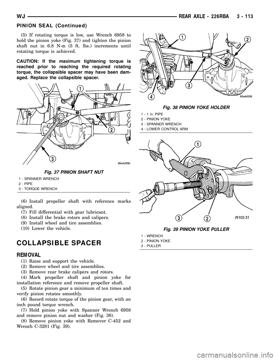
(5) If rotating torque is low, use Wrench 6958 to
hold the pinion yoke (Fig. 37) and tighten the pinion
shaft nut in 6.8 N´m (5 ft. lbs.) increments until
rotating torque is achieved.
CAUTION: If the maximum tightening torque is
reached prior to reaching the required rotating
torque, the collapsible spacer may have been dam-
aged. Replace the collapsible spacer.
(6) Install propeller shaft with reference marks
aligned.
(7) Fill differential with gear lubricant.
(8) Install the brake rotors and calipers.
(9) Install wheel and tire assemblies.
(10) Lower the vehicle.
COLLAPSIBLE SPACER
REMOVAL
(1) Raise and support the vehicle.
(2) Remove wheel and tire assemblies.
(3) Remove rear brake calipers and rotors.
(4) Mark propeller shaft and pinion yoke for
installation reference and remove propeller shaft.
(5) Rotate pinion gear a minimum of ten times and
verify pinion rotates smoothly.
(6) Record rotate torque of the pinion gear, with an
inch pound torque wrench.
(7) Hold pinion yoke with Spanner Wrench 6958
and remove pinion nut and washer (Fig. 38).
(8) Remove pinion yoke with Remover C-452 and
Wrench C-3281 (Fig. 39).
Fig. 37 PINION SHAFT NUT
1 - SPANNER WRENCH
2 - PIPE
3 - TORQUE WRENCH
Fig. 38 PINION YOKE HOLDER
1 - 1 in. PIPE
2 - PINION YOKE
3 - SPANNER WRENCH
4 - LOWER CONTROL ARM
Fig. 39 PINION YOKE PULLER
1 - WRENCH
2 - PINION YOKE
3 - PULLER
WJREAR AXLE - 226RBA 3 - 113
PINION SEAL (Continued)
Page 160 of 2199
NOTE: If more than 380 N´m (280 ft. lbs.) torque is
required to crush the collapsible spacer, the spacer
is defective and must be replaced.
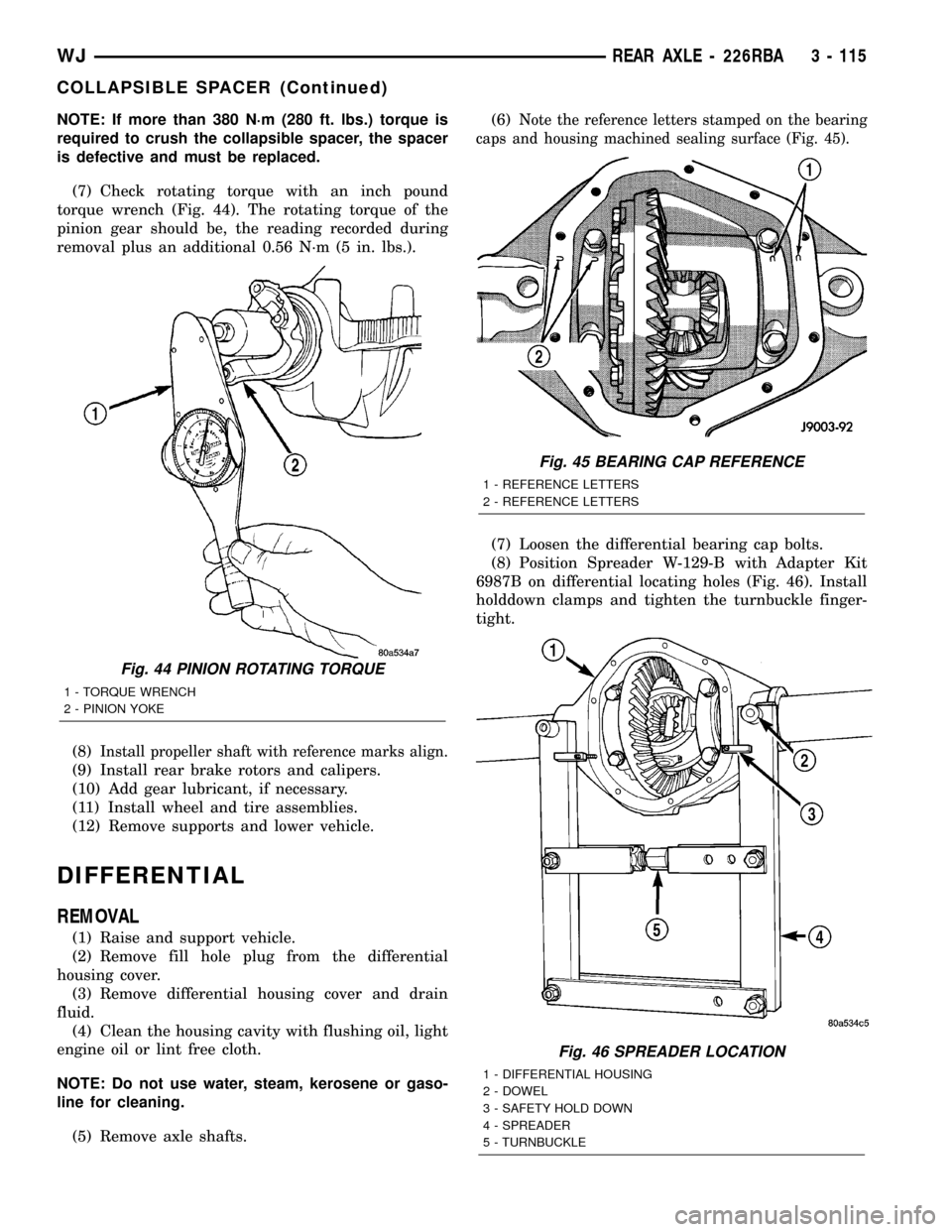
(7) Check rotating torque with an inch pound
torque wrench (Fig. 44). The rotating torque of the
pinion gear should be, the reading recorded during
removal plus an additional 0.56 N´m (5 in. lbs.).
(8)
Install propeller shaft with reference marks align.
(9) Install rear brake rotors and calipers.
(10) Add gear lubricant, if necessary.
(11) Install wheel and tire assemblies.
(12) Remove supports and lower vehicle.
DIFFERENTIAL
REMOVAL
(1) Raise and support vehicle.
(2) Remove fill hole plug from the differential
housing cover.
(3) Remove differential housing cover and drain
fluid.
(4) Clean the housing cavity with flushing oil, light
engine oil or lint free cloth.
NOTE: Do not use water, steam, kerosene or gaso-
line for cleaning.
(5) Remove axle shafts.(6)
Note the reference letters stamped on the bearing
caps and housing machined sealing surface (Fig. 45).
(7) Loosen the differential bearing cap bolts.
(8) Position Spreader W-129-B with Adapter Kit
6987B on differential locating holes (Fig. 46). Install
holddown clamps and tighten the turnbuckle finger-
tight.
Fig. 44 PINION ROTATING TORQUE
1 - TORQUE WRENCH
2 - PINION YOKE
Fig. 45 BEARING CAP REFERENCE
1 - REFERENCE LETTERS
2 - REFERENCE LETTERS
Fig. 46 SPREADER LOCATION
1 - DIFFERENTIAL HOUSING
2 - DOWEL
3 - SAFETY HOLD DOWN
4 - SPREADER
5 - TURNBUCKLE
WJREAR AXLE - 226RBA 3 - 115
COLLAPSIBLE SPACER (Continued)
Page 164 of 2199
(12) Install cover and tighten bolts in a criss-cross
pattern to 41 N´m (30 ft. lbs.).
(13) Refill the differential with Mopar Hypoid
Gear Lubricant or equivalent to bottom of the fill
plug hole.
(14) Install fill hole plug.
(15) Remove support and lower the vehicle.
DIFFERENTIAL - TRAC-LOK
DIAGNOSIS AND TESTING
The most common problem is a chatter noise when
turning corners. Before removing the unit for repair,
drain, flush and refill the axle with the specified
lubricant. A container of Mopar Trac-loktLubricant
(friction modifier) should be added after repair ser-
vice or during a lubricant change.
After changing the lubricant, drive the vehicle and
make 10 to 12 slow, figure-eight turns. This maneu-
ver will pump lubricant through the clutches. This
will correct the condition in most instances. If the
chatter persists, clutch damage could have occurred.
DIFFERENTIAL TEST
The differential can be tested without removing the
differential case by measuring rotating torque. Make
sure brakes are not dragging during this measure-
ment.
(1) Place blocks in front and rear of both front
wheels.
(2) Raise one rear wheel until it is completely off
the ground.
(3) Engine off, transmission in neutral, and park-
ing brake off.
(4) Remove wheel and bolt Special Tool 6790 or
equivalent tool to studs.
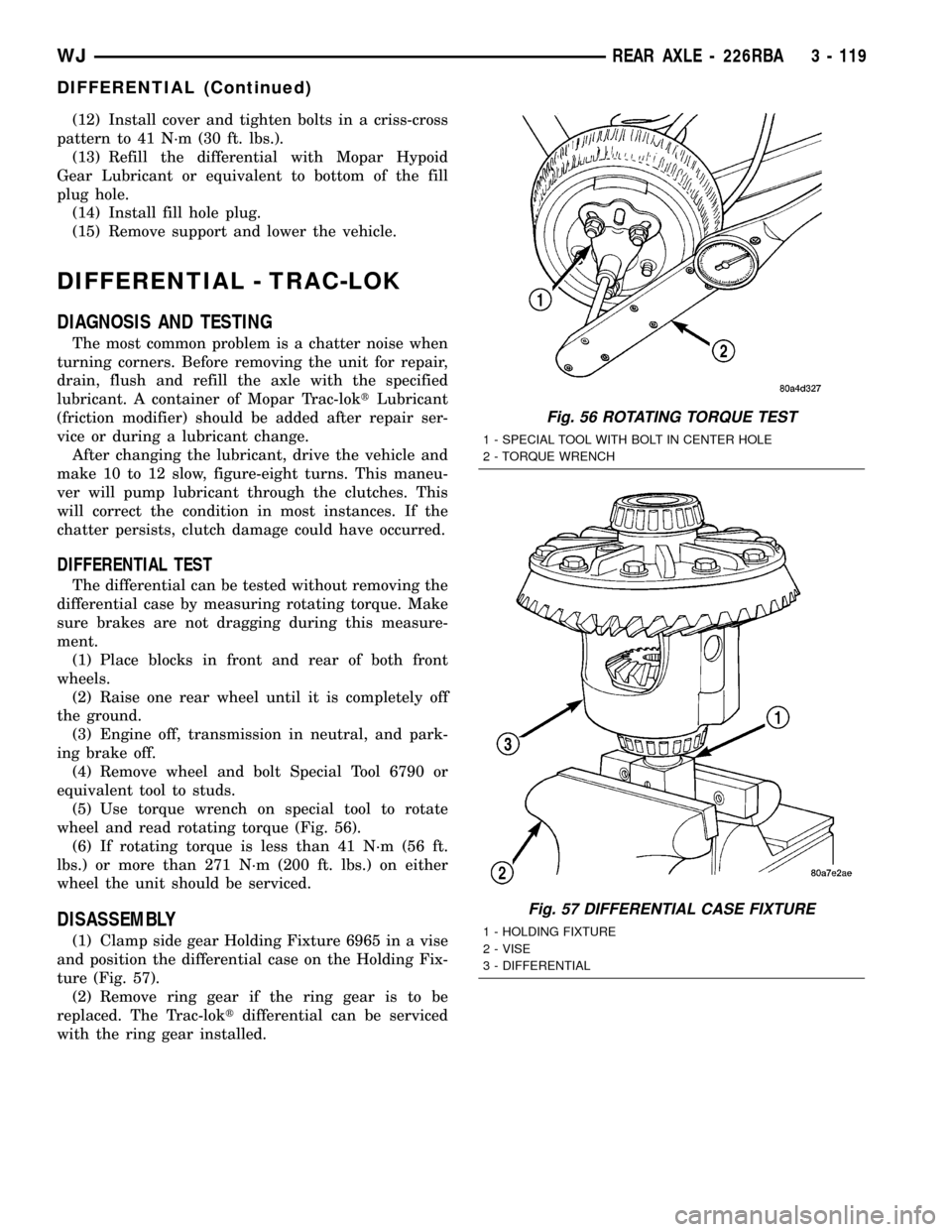
(5) Use torque wrench on special tool to rotate
wheel and read rotating torque (Fig. 56).
(6) If rotating torque is less than 41 N´m (56 ft.
lbs.) or more than 271 N´m (200 ft. lbs.) on either
wheel the unit should be serviced.
DISASSEMBLY
(1) Clamp side gear Holding Fixture 6965 in a vise
and position the differential case on the Holding Fix-
ture (Fig. 57).
(2) Remove ring gear if the ring gear is to be
replaced. The Trac-loktdifferential can be serviced
with the ring gear installed.
Fig. 56 ROTATING TORQUE TEST
1 - SPECIAL TOOL WITH BOLT IN CENTER HOLE
2 - TORQUE WRENCH
Fig. 57 DIFFERENTIAL CASE FIXTURE
1 - HOLDING FIXTURE
2 - VISE
3 - DIFFERENTIAL
WJREAR AXLE - 226RBA 3 - 119
DIFFERENTIAL (Continued)
Page 183 of 2199
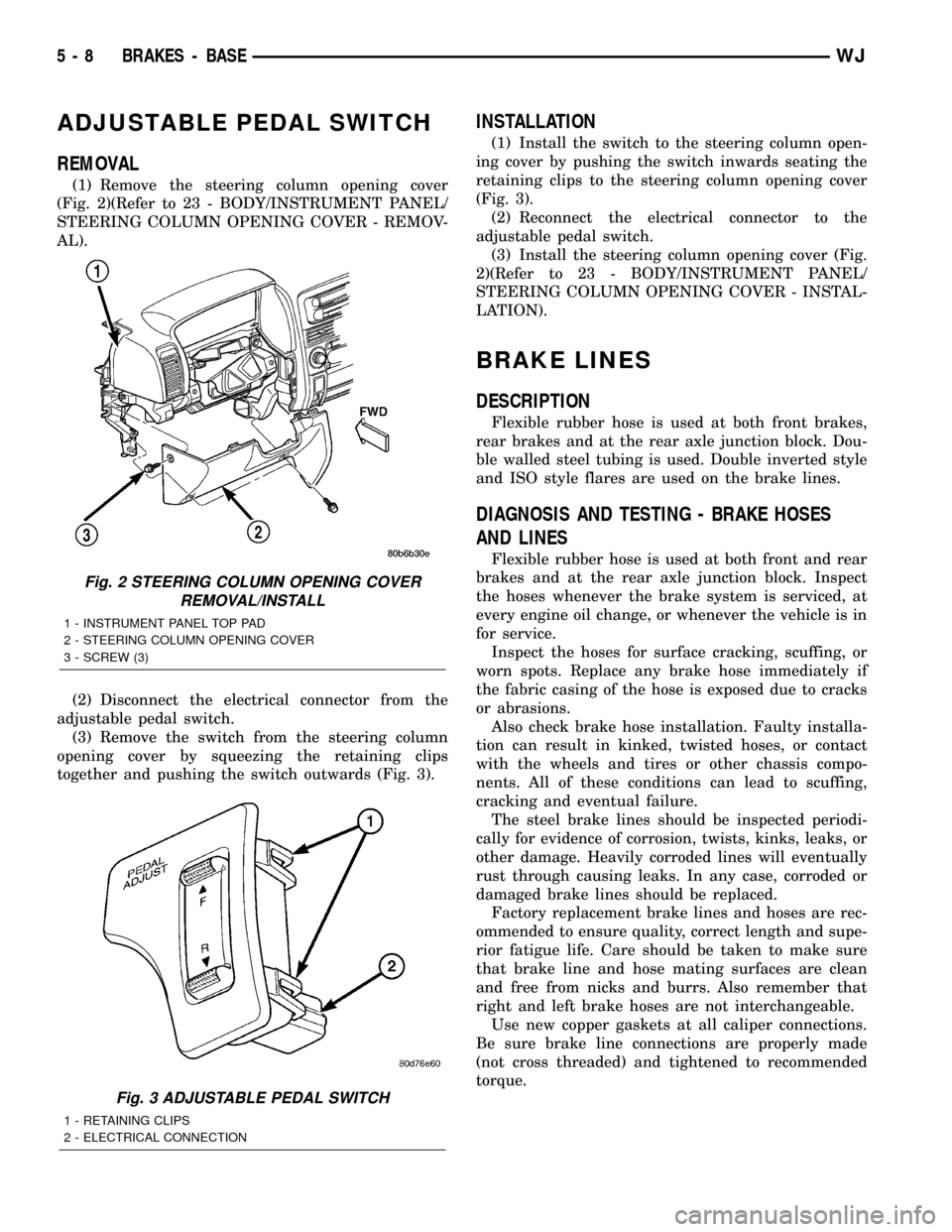
ADJUSTABLE PEDAL SWITCH
REMOVAL
(1) Remove the steering column opening cover
(Fig. 2)(Refer to 23 - BODY/INSTRUMENT PANEL/
STEERING COLUMN OPENING COVER - REMOV-
AL).
(2) Disconnect the electrical connector from the
adjustable pedal switch.
(3) Remove the switch from the steering column
opening cover by squeezing the retaining clips
together and pushing the switch outwards (Fig. 3).
INSTALLATION
(1) Install the switch to the steering column open-
ing cover by pushing the switch inwards seating the
retaining clips to the steering column opening cover
(Fig. 3).
(2) Reconnect the electrical connector to the
adjustable pedal switch.
(3) Install the steering column opening cover (Fig.
2)(Refer to 23 - BODY/INSTRUMENT PANEL/
STEERING COLUMN OPENING COVER - INSTAL-
LATION).
BRAKE LINES
DESCRIPTION
Flexible rubber hose is used at both front brakes,
rear brakes and at the rear axle junction block. Dou-
ble walled steel tubing is used. Double inverted style
and ISO style flares are used on the brake lines.
DIAGNOSIS AND TESTING - BRAKE HOSES
AND LINES
Flexible rubber hose is used at both front and rear
brakes and at the rear axle junction block. Inspect
the hoses whenever the brake system is serviced, at
every engine oil change, or whenever the vehicle is in
for service.
Inspect the hoses for surface cracking, scuffing, or
worn spots. Replace any brake hose immediately if
the fabric casing of the hose is exposed due to cracks
or abrasions.
Also check brake hose installation. Faulty installa-
tion can result in kinked, twisted hoses, or contact
with the wheels and tires or other chassis compo-
nents. All of these conditions can lead to scuffing,
cracking and eventual failure.
The steel brake lines should be inspected periodi-
cally for evidence of corrosion, twists, kinks, leaks, or
other damage. Heavily corroded lines will eventually
rust through causing leaks. In any case, corroded or
damaged brake lines should be replaced.
Factory replacement brake lines and hoses are rec-
ommended to ensure quality, correct length and supe-
rior fatigue life. Care should be taken to make sure
that brake line and hose mating surfaces are clean
and free from nicks and burrs. Also remember that
right and left brake hoses are not interchangeable.
Use new copper gaskets at all caliper connections.
Be sure brake line connections are properly made
(not cross threaded) and tightened to recommended
torque.
Fig. 2 STEERING COLUMN OPENING COVER
REMOVAL/INSTALL
1 - INSTRUMENT PANEL TOP PAD
2 - STEERING COLUMN OPENING COVER
3 - SCREW (3)
Fig. 3 ADJUSTABLE PEDAL SWITCH
1 - RETAINING CLIPS
2 - ELECTRICAL CONNECTION
5 - 8 BRAKES - BASEWJ
Page 186 of 2199
shoe lining against the inner surface of the disc
brake rotor. At the same time, fluid pressure within
the piston bores forces the caliper to slide inward on
the slide pins. This action brings the outboard brake
shoe lining into contact with the outer surface of the
disc brake rotor.
Fluid pressure acting simultaneously on the pis-
tons and caliper to produces a strong clamping
action. When sufficient force is applied, friction will
stop the rotors from turning and bring the vehicle to
a stop.
Application and release of the brake pedal gener-
ates only a very slight movement of the caliper and
pistons. Upon release of the pedal, the caliper and
pistons return to a rest position. The brake shoes do
not retract an appreciable distance from the rotor. In
fact, clearance is usually at, or close to zero. The rea-
sons for this are to keep road debris from getting
between the rotor and lining and in wiping the rotor
surface clear each revolution.
The caliper piston seals control the amount of pis-
ton extension needed to compensate for normal lining
wear.
During brake application, the seals are deflected
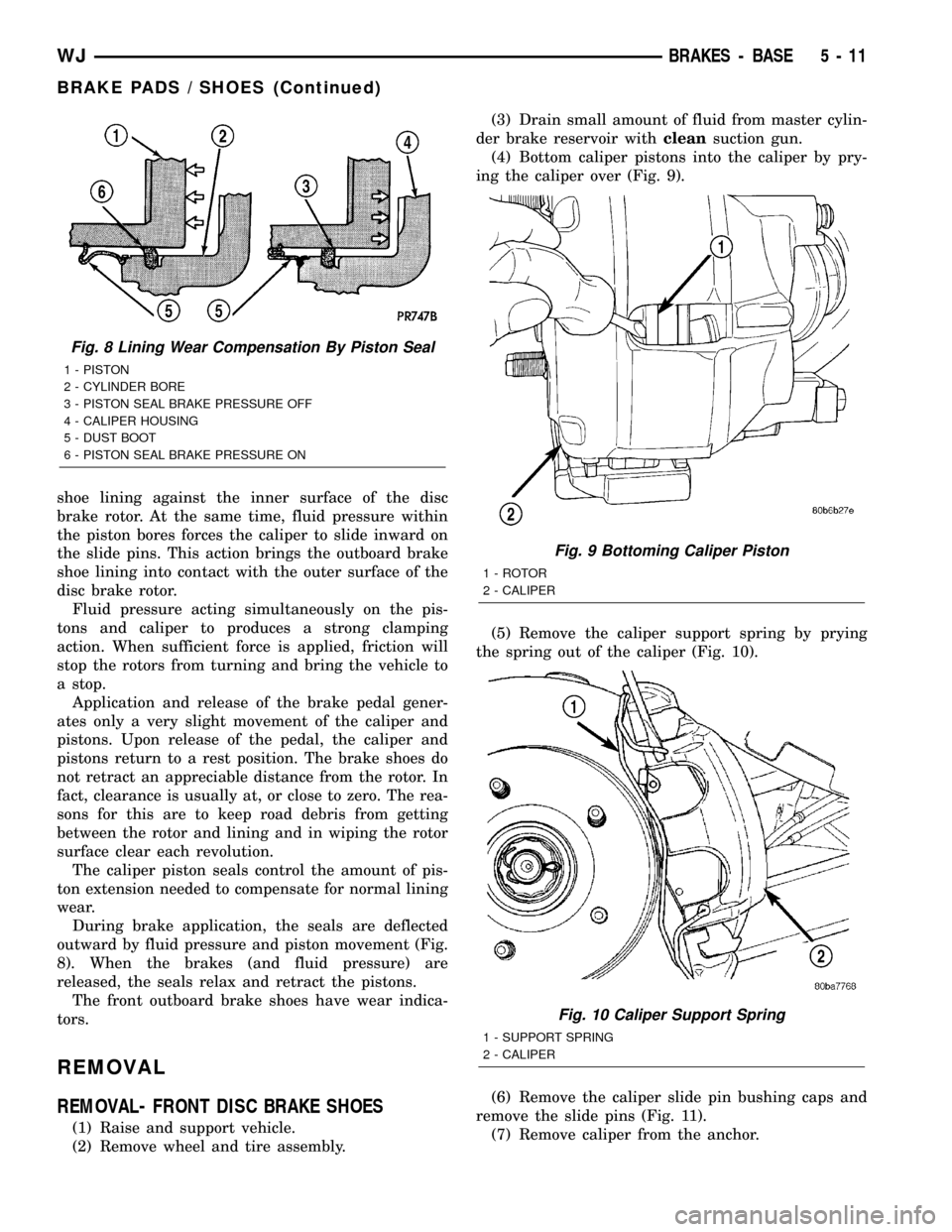
outward by fluid pressure and piston movement (Fig.
8). When the brakes (and fluid pressure) are
released, the seals relax and retract the pistons.
The front outboard brake shoes have wear indica-
tors.
REMOVAL
REMOVAL- FRONT DISC BRAKE SHOES
(1) Raise and support vehicle.
(2) Remove wheel and tire assembly.(3) Drain small amount of fluid from master cylin-
der brake reservoir withcleansuction gun.
(4) Bottom caliper pistons into the caliper by pry-
ing the caliper over (Fig. 9).
(5) Remove the caliper support spring by prying
the spring out of the caliper (Fig. 10).
(6) Remove the caliper slide pin bushing caps and
remove the slide pins (Fig. 11).
(7) Remove caliper from the anchor.
Fig. 8 Lining Wear Compensation By Piston Seal
1 - PISTON
2 - CYLINDER BORE
3 - PISTON SEAL BRAKE PRESSURE OFF
4 - CALIPER HOUSING
5 - DUST BOOT
6 - PISTON SEAL BRAKE PRESSURE ON
Fig. 9 Bottoming Caliper Piston
1 - ROTOR
2 - CALIPER
Fig. 10 Caliper Support Spring
1 - SUPPORT SPRING
2 - CALIPER
WJBRAKES - BASE 5 - 11
BRAKE PADS / SHOES (Continued)
Page 187 of 2199
(8) Secure caliper to nearby suspension part with
wire.Do not allow brake hose to support caliper
weight.
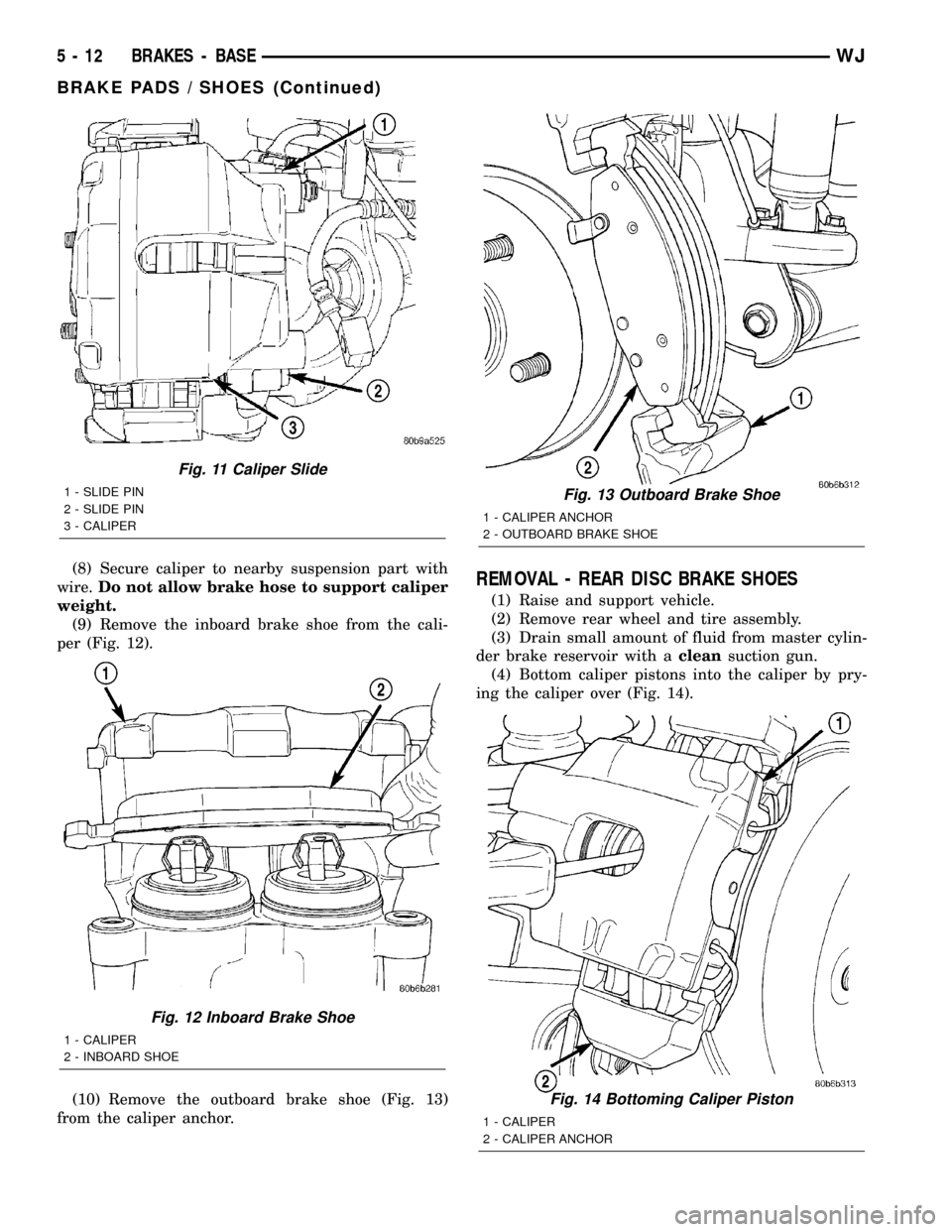
(9) Remove the inboard brake shoe from the cali-
per (Fig. 12).
(10) Remove the outboard brake shoe (Fig. 13)
from the caliper anchor.REMOVAL - REAR DISC BRAKE SHOES
(1) Raise and support vehicle.
(2) Remove rear wheel and tire assembly.
(3) Drain small amount of fluid from master cylin-
der brake reservoir with acleansuction gun.
(4) Bottom caliper pistons into the caliper by pry-
ing the caliper over (Fig. 14).
Fig. 11 Caliper Slide
1 - SLIDE PIN
2 - SLIDE PIN
3 - CALIPER
Fig. 12 Inboard Brake Shoe
1 - CALIPER
2 - INBOARD SHOE
Fig. 13 Outboard Brake Shoe
1 - CALIPER ANCHOR
2 - OUTBOARD BRAKE SHOE
Fig. 14 Bottoming Caliper Piston
1 - CALIPER
2 - CALIPER ANCHOR
5 - 12 BRAKES - BASEWJ
BRAKE PADS / SHOES (Continued)
Page 189 of 2199
(8) Install wheel and tire assembly.
(9) Remove support and lower vehicle.
(10) Pump brake pedal until caliper pistons and
brake shoes are seated and a firm brake pedal is
obtained.
(11) Fill brake fluid.
INSTALLATION - REAR DISC BRAKE SHOES
(1) Install the inboard brake shoe onto the caliper
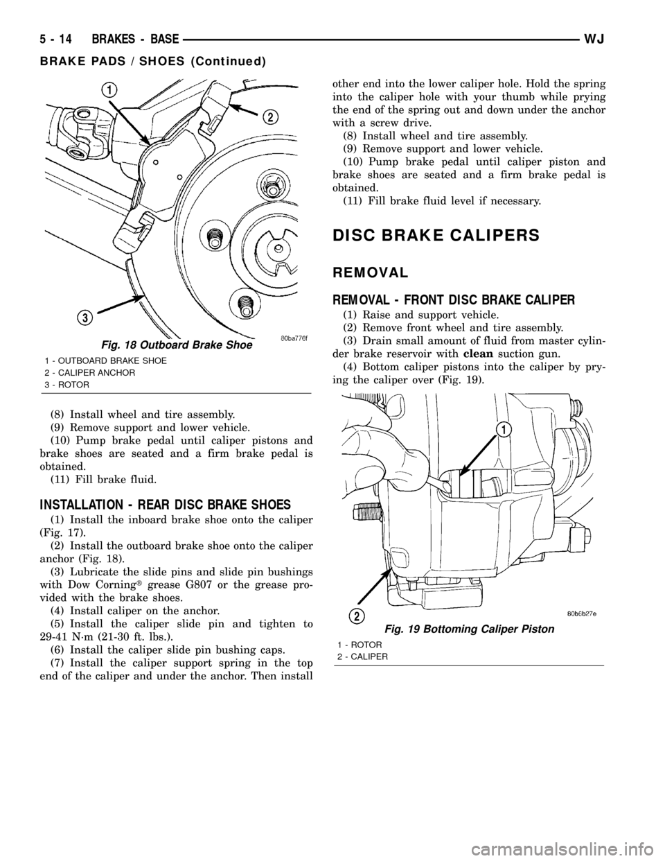
(Fig. 17).
(2) Install the outboard brake shoe onto the caliper
anchor (Fig. 18).
(3) Lubricate the slide pins and slide pin bushings
with Dow Corningtgrease G807 or the grease pro-
vided with the brake shoes.
(4) Install caliper on the anchor.
(5) Install the caliper slide pin and tighten to
29-41 N´m (21-30 ft. lbs.).
(6) Install the caliper slide pin bushing caps.
(7) Install the caliper support spring in the top
end of the caliper and under the anchor. Then installother end into the lower caliper hole. Hold the spring
into the caliper hole with your thumb while prying
the end of the spring out and down under the anchor
with a screw drive.
(8) Install wheel and tire assembly.
(9) Remove support and lower vehicle.
(10) Pump brake pedal until caliper piston and
brake shoes are seated and a firm brake pedal is
obtained.
(11) Fill brake fluid level if necessary.
DISC BRAKE CALIPERS
REMOVAL
REMOVAL - FRONT DISC BRAKE CALIPER
(1) Raise and support vehicle.
(2) Remove front wheel and tire assembly.
(3) Drain small amount of fluid from master cylin-
der brake reservoir withcleansuction gun.
(4) Bottom caliper pistons into the caliper by pry-
ing the caliper over (Fig. 19).
Fig. 18 Outboard Brake Shoe
1 - OUTBOARD BRAKE SHOE
2 - CALIPER ANCHOR
3 - ROTOR
Fig. 19 Bottoming Caliper Piston
1 - ROTOR
2 - CALIPER
5 - 14 BRAKES - BASEWJ
BRAKE PADS / SHOES (Continued)
Page 190 of 2199
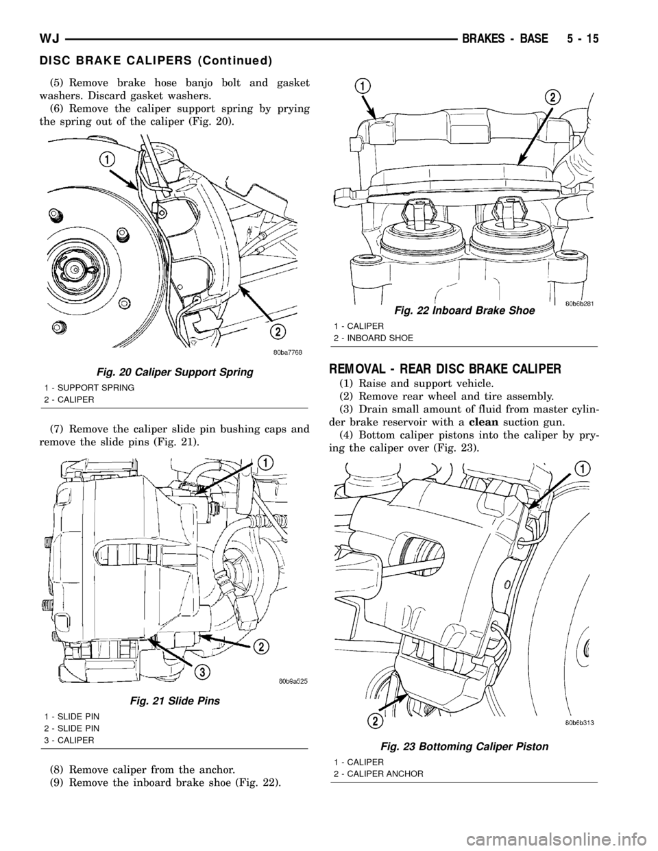
(5) Remove brake hose banjo bolt and gasket
washers. Discard gasket washers.
(6) Remove the caliper support spring by prying
the spring out of the caliper (Fig. 20).
(7) Remove the caliper slide pin bushing caps and
remove the slide pins (Fig. 21).
(8) Remove caliper from the anchor.
(9) Remove the inboard brake shoe (Fig. 22).
REMOVAL - REAR DISC BRAKE CALIPER
(1) Raise and support vehicle.
(2) Remove rear wheel and tire assembly.
(3) Drain small amount of fluid from master cylin-
der brake reservoir with acleansuction gun.
(4) Bottom caliper pistons into the caliper by pry-
ing the caliper over (Fig. 23).
Fig. 20 Caliper Support Spring
1 - SUPPORT SPRING
2 - CALIPER
Fig. 21 Slide Pins
1 - SLIDE PIN
2 - SLIDE PIN
3 - CALIPER
Fig. 22 Inboard Brake Shoe
1 - CALIPER
2 - INBOARD SHOE
Fig. 23 Bottoming Caliper Piston
1 - CALIPER
2 - CALIPER ANCHOR
WJBRAKES - BASE 5 - 15
DISC BRAKE CALIPERS (Continued)
Page 197 of 2199
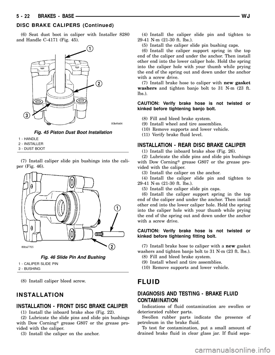
(6) Seat dust boot in caliper with Installer 8280
and Handle C-4171 (Fig. 45).
(7) Install caliper slide pin bushings into the cali-
per (Fig. 46).
(8) Install caliper bleed screw.
INSTALLATION
INSTALLATION - FRONT DISC BRAKE CALIPER
(1) Install the inboard brake shoe (Fig. 22).
(2) Lubricate the slide pins and slide pin bushings
with Dow Corningtgrease G807 or the grease pro-
vided with the caliper.
(3) Install the caliper on the anchor.(4) Install the caliper slide pin and tighten to
29-41 N´m (21-30 ft. lbs.).
(5) Install the caliper slide pin bushing caps.
(6) Install the caliper support spring in the top
end of the caliper and under the anchor. Then install
other end into the lower caliper hole. Hold the spring
into the caliper hole with your thumb while prying
the end of the spring out and down under the anchor
with a screw drive.
(7) Install brake hose to caliper withnew gasket
washersand tighten banjo bolt to 31 N´m (23 ft.
lbs.).
CAUTION: Verify brake hose is not twisted or
kinked before tightening banjo bolt.
(8) Fill and bleed brake system.
(9) Install wheel and tire assemblies.
(10) Remove supports and lower vehicle.
(11) Verify brake fluid level.
INSTALLATION - REAR DISC BRAKE CALIPER
(1) Install the inboard brake shoe (Fig. 26).
(2) Lubricate the slide pins and slide pin bushings
with Dow Corningtgrease G807 or the grease pro-
vided with the caliper.
(3) Install the caliper on the anchor.
(4) Install the caliper slide pin and tighten to
29-41 N´m (21-30 ft. lbs.).
(5) Install the caliper slide pin caps.
(6) Install the caliper support spring in the top
end of the caliper and under the anchor. Then install
other end into the lower caliper hole. Hold the spring
into the caliper hole with your thumb while prying
the end of the spring out and down under the anchor
with a screw drive.
CAUTION: Verify brake hose is not twisted or
kinked before tightening fitting bolt.
(7) Install brake hose to caliper with anewgasket
washers and tighten banjo bolt to 31 N´m (23 ft. lbs.).
(8) Fill and bleed brake system.
(9) Install wheel and tire assemblies.
(10) Remove supports and lower vehicle.
FLUID
DIAGNOSIS AND TESTING - BRAKE FLUID
CONTAMINATION
Indications of fluid contamination are swollen or
deteriorated rubber parts.
Swollen rubber parts indicate the presence of
petroleum in the brake fluid.
To test for contamination, put a small amount of
drained brake fluid in clear glass jar. If fluid sepa-
Fig. 45 Piston Dust Boot Installation
1 - HANDLE
2 - INSTALLER
3 - DUST BOOT
Fig. 46 Slide Pin And Bushing
1 - CALIPER SLIDE PIN
2 - BUSHING
5 - 22 BRAKES - BASEWJ
DISC BRAKE CALIPERS (Continued)