spec JEEP GRAND CHEROKEE 2003 WJ / 2.G Workshop Manual
[x] Cancel search | Manufacturer: JEEP, Model Year: 2003, Model line: GRAND CHEROKEE, Model: JEEP GRAND CHEROKEE 2003 WJ / 2.GPages: 2199, PDF Size: 76.01 MB
Page 1903 of 2199

(3) Install fascia, refer to (Refer to 13 - FRAMES
& BUMPERS/BUMPERS/FRONT FASCIA - INSTAL-
LATION).
HEADLAMP MOUNTING
MODULE
REMOVAL
CAUTION: Take special care when handling the
HMM not to damage the upper mounting tabs. Step
#3 must be performed prior to removing HMM from
the vehicle to prevent damage to HMM.
(1) Remove fascia, refer to (Refer to 13 - FRAMES
& BUMPERS/BUMPERS/FRONT FASCIA - REMOV-
AL).
(2) Remove inner fender liner.
(3) Reach into the wheelhouse opening and disen-
gage the retainer attaching the HMM to each side of
the body.
(4) Remove bolts attaching headlamp mounting
module to body (Fig. 10).
(5) Disconnect headlamp wire harness connectors.
(6) Separate headlamp mounting module from
vehicle.
INSTALLATION
(1) Position headlamp mounting module at vehicle.
(2) Connect headlamp wire harness connectors.
(3) Engage the retainer attaching the HMM to
each side of the body.
(4) Install bolts attaching headlamp mounting
module to body (Fig. 10).
(5) Install inner fender liner.
(6) Install front fascia, refer to (Refer to 13 -
FRAMES & BUMPERS/BUMPERS/FRONT FASCIA
- INSTALLATION).
LUGGAGE RACK
REMOVAL
NOTE: The skid strips are attached to the roof
panel with adhesive.
(1) Using a trim stick, or other suitable device, pry
support cover off.
(2) If necessary, slide the crossbars to expose the
screws attaching the slide rails to the supports.
(3) Remove the screws retaining the slide rails to
the supports.
Fig. 10 Headlamp Mounting Module
1 - CONNECTOR
2 - CONNECTOR3 - MOUNTING BRACKET
4 - HEADLAMP MODULE
23 - 30 EXTERIORWJ
GRILLE (Continued)
Page 1907 of 2199

(6) Remove bolts attaching hinges to hood.
(7) With the aid of a helper, remove hood from
vehicle.
INSTALLATION
(1) Position hood on hinges.
(2) Install bolts finger-tight.
(3) Align hinges with installation reference marks
and tighten bolts.
(4) Install hood support prop rods.
(5) Connect underhood lamp connector.
(6) Inspect hood for proper alignment and adjust
as necessary.
ADJUSTMENTS
HOOD ADJUSTMENT
The hood attaching holes are enlarged to aid front,
back and side to side adjustment.
(1) If hood is low in relation to cowl panel, insert
shims between hinge and hood.
(2) Adjust hood bumper in or out to adjust hood-
to-fender height alignment.
(3) Adjust the hood latch as necessary. Tighten the
nuts to 11N´m (8 ft. lbs.).
(4) Align the latch striker so that striker enters
the latch squarely and without binding.
INSULATION
REMOVAL
(1) Raise the hood.
(2) Remove the insulation panel fasteners.
(3) Remove the hood insulation panel.
INSTALLATION
(1) Position the insulation panel on the underside
of the hood.
(2) Install the insulation panel fasteners.
(3) Close the hood.
LATCH
REMOVAL
(1) Remove nuts attaching latch to radiator cross-
member support (Fig. 2).
(2) Disconnect hood release cable from latch.
(3) Separate latch from vehicle.
INSTALLATION
(1) Connect latch release cable to latch.
(2) Position latch on radiator crossmember sup-
port.
(3) Install nuts attaching latch to radiator cross-
member support. Tighten nuts to 11 N´m (8 ft. lbs.)
torque (Fig. 2).
Fig. 2 Hood Latch
1 - HOOD RELEASE CABLE
2-LATCH
3 - BUMPER
23 - 34 HOODWJ
HOOD (Continued)
Page 1920 of 2199

REMOVAL
WARNING: ON VEHICLES EQUIPPED WITH AIR-
BAGS, DISABLE THE AIRBAG SYSTEM BEFORE
ATTEMPTING ANY STEERING WHEEL, STEERING
COLUMN, OR INSTRUMENT PANEL COMPONENT
DIAGNOSIS OR SERVICE. DISCONNECT AND ISO-
LATE THE BATTERY NEGATIVE (GROUND) CABLE,
THEN WAIT TWO MINUTES FOR THE AIRBAG SYS-
TEM CAPACITOR TO DISCHARGE BEFORE PER-
FORMING FURTHER DIAGNOSIS OR SERVICE. THIS
IS THE ONLY SURE WAY TO DISABLE THE AIRBAG
SYSTEM. FAILURE TO TAKE THE PROPER PRE-
CAUTIONS COULD RESULT IN ACCIDENTAL AIR-
BAG DEPLOYMENT AND POSSIBLE PERSONAL
INJURY.
(1) Disconnect and isolate the battery negative
cable.
(2) Roll the glove box down from the instrument
panel. (Refer to 23 - BODY/INSTRUMENT PANEL/
GLOVE BOX - STANDARD PROCEDURE - GLOVE
BOX ROLL DOWN).
NOTE: Be certain to use care not to damage or
remove the glove box hinge bumpers on the lower
instrument panel glove box opening reinforcement
when removing the glove box from the instrument
panel.
(3) Firmly grip both ends of the glove box door,
then twist and pull the door as necessary to disen-
gage the inboard hinge hook from the inboard hinge
pin on the instrument panel and reorient the hook to
the underside of the hinge pin (Fig. 18).(4) Raise the glove box door until it is perpendicu-
lar to the instrument panel.
(5) Twist the door slightly in the counterclockwise
direction and use a jiggling action to disengage the
remaining two hinge hooks from their respective
hinge pins on the instrument panel.
(6) Remove the glove box from the instrument
panel.
INSTALLATION
WARNING: ON VEHICLES EQUIPPED WITH AIR-
BAGS, DISABLE THE AIRBAG SYSTEM BEFORE
ATTEMPTING ANY STEERING WHEEL, STEERING
COLUMN, OR INSTRUMENT PANEL COMPONENT
DIAGNOSIS OR SERVICE. DISCONNECT AND ISO-
LATE THE BATTERY NEGATIVE (GROUND) CABLE,
THEN WAIT TWO MINUTES FOR THE AIRBAG SYS-
TEM CAPACITOR TO DISCHARGE BEFORE PER-
FORMING FURTHER DIAGNOSIS OR SERVICE. THIS
IS THE ONLY SURE WAY TO DISABLE THE AIRBAG
SYSTEM. FAILURE TO TAKE THE PROPER PRE-
CAUTIONS COULD RESULT IN ACCIDENTAL AIR-
BAG DEPLOYMENT AND POSSIBLE PERSONAL
INJURY.
NOTE: Be certain to use care not to damage or
remove the glove box hinge bumpers on the lower
instrument panel glove box opening reinforcement
when installing the glove box onto the instrument
panel.
(1) Position the glove box to the instrument panel
with the outboard hinge hook oriented over the out-
board hinge pin and the center hinge hook oriented
under the center hinge pin (Fig. 18).
(2) Raise the glove box door until it is perpendicu-
lar to the instrument panel.
(3) Firmly grip both ends of the glove box door and
twist the door slightly in the clockwise direction to
engage the inboard glove box hinge hook over the
inboard hinge pin on the instrument panel.
(4) Roll the glove box back up into the instrument
panel. (Refer to 23 - BODY/INSTRUMENT PANEL/
GLOVE BOX - STANDARD PROCEDURE - GLOVE
BOX ROLL DOWN).
(5) Reconnect the battery negative cable.
Fig. 18 Glove Box Remove/Install
1 - GLOVE BOX HINGE HOOKS AND HINGE PINS (3)
WJINSTRUMENT PANEL SYSTEM 23 - 47
GLOVE BOX (Continued)
Page 1954 of 2199
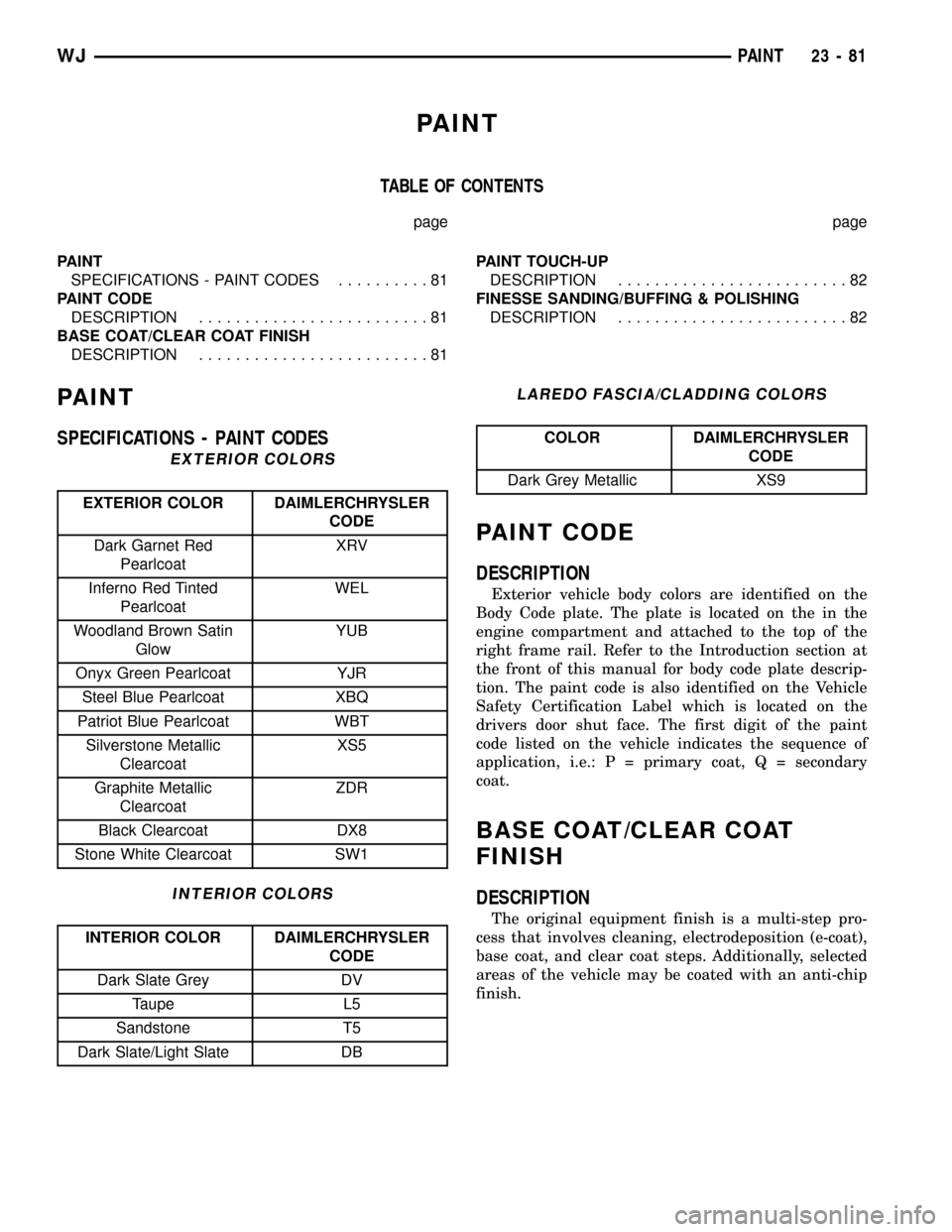
PAINT
TABLE OF CONTENTS
page page
PAINT
SPECIFICATIONS - PAINT CODES..........81
PAINT CODE
DESCRIPTION.........................81
BASE COAT/CLEAR COAT FINISH
DESCRIPTION.........................81PAINT TOUCH-UP
DESCRIPTION.........................82
FINESSE SANDING/BUFFING & POLISHING
DESCRIPTION.........................82
PAINT
SPECIFICATIONS - PAINT CODES
EXTERIOR COLORS
EXTERIOR COLOR DAIMLERCHRYSLER
CODE
Dark Garnet Red
PearlcoatXRV
Inferno Red Tinted
PearlcoatWEL
Woodland Brown Satin
GlowYUB
Onyx Green Pearlcoat YJR
Steel Blue Pearlcoat XBQ
Patriot Blue Pearlcoat WBT
Silverstone Metallic
ClearcoatXS5
Graphite Metallic
ClearcoatZDR
Black Clearcoat DX8
Stone White Clearcoat SW1
INTERIOR COLORS
INTERIOR COLOR DAIMLERCHRYSLER
CODE
Dark Slate Grey DV
Taupe L5
Sandstone T5
Dark Slate/Light Slate DB
LAREDO FASCIA/CLADDING COLORS
COLOR DAIMLERCHRYSLER
CODE
Dark Grey Metallic XS9
PAINT CODE
DESCRIPTION
Exterior vehicle body colors are identified on the
Body Code plate. The plate is located on the in the
engine compartment and attached to the top of the
right frame rail. Refer to the Introduction section at
the front of this manual for body code plate descrip-
tion. The paint code is also identified on the Vehicle
Safety Certification Label which is located on the
drivers door shut face. The first digit of the paint
code listed on the vehicle indicates the sequence of
application, i.e.: P = primary coat, Q = secondary
coat.
BASE COAT/CLEAR COAT
FINISH
DESCRIPTION
The original equipment finish is a multi-step pro-
cess that involves cleaning, electrodeposition (e-coat),
base coat, and clear coat steps. Additionally, selected
areas of the vehicle may be coated with an anti-chip
finish.
WJPAINT 23 - 81
Page 1969 of 2199

SUNROOF
TABLE OF CONTENTS
page page
SUNROOF
DESCRIPTION.........................96
DIAGNOSIS AND TESTING - SUNROOF......96
DRAIN TUBE
REMOVAL............................100
INSTALLATION........................100
CONTROL MODULE
REMOVAL............................101
INSTALLATION........................101
DRIVE MOTOR
REMOVAL............................101
INSTALLATION........................101
WIND DEFLECTOR
REMOVAL............................102INSTALLATION........................102
GLASS PANEL
REMOVAL............................102
INSTALLATION........................103
ADJUSTMENTS
ADJUSTMENTS - FIT.................103
ADJUSTMENT - TIMING...............103
SUNSHADE
REMOVAL............................103
INSTALLATION........................103
HOUSING ASSEMBLY
REMOVAL............................104
INSTALLATION........................104
SUNROOF
DESCRIPTION
WARNING: Keep fingers and other body parts out
of sunroof opening at all times.
The sunroof features a power sliding glass panel
and a sunshade which can be manually positioned
anywhere along its travel, rearward of glass panel
front edge.
The sunroof is electrically operated from a switch
located on the mini overhead console. To operate the
sunroof the ignition switch must be in the On/Run
position. The sunroof has both manual and Express
Open modes of operation when opening. To open the
sunroof in the Express Open mode, the switch is
pressed rearward for less than1 second.This causes
the sunroof glass to automatically retract and stop at
a position slightly forward of full open that reduces
low speed wind buffeting. The sunroof can also be
opened manually by pressing and holding the switch
rearward. Once the switch is held reward for more
than1 second,the glass will retract in the manual
mode. Releasing the switch at any time during travel
will cause the sunroof to stop at the current position.
To close the sunroof from an open position, the
switch must be pushed forward and held until the
sunroof glass comes to a complete stop. Releasing the
switch at any time in this mode will cause the sun-
roof to stop at the current position.
To vent the sunroof from the closed position, the
switch is pushed forward and held. Releasing theswitch at any time during travel will cause the sun-
roof to stop at the current vent position. To reach the
fully vented position, continue to hold the switch for-
ward until vent motion stops. To close the sunroof
from the vent position, push and hold the switch
rearward until the glass comes to a complete stop.
DIAGNOSIS AND TESTING - SUNROOF
CAUTION: The sunroof motor is only to be powered
through the vehicle battery and vehicle wire har-
ness. Applying power to the sunroof motor leads
will cause failure of the sunroof control unit.
Before beginning sunroof diagnostics verify that all
other power accessories are in proper operating con-
dition. Refer to Sunroof Diagnostic Chart for possible
causes. If not, a common electrical problem may
exist. Refer to Group 8W, Wiring Diagrams, of this
publication for circuit, splice and component descrip-
tions. Check the condition of the circuit protection
(20 amp high current fuse (battery feed) located in
the Power Distribution Center (PDC). Check the
cover of the PDC for location of the fuse. Check for
correct operation of the sunroof delay relay. Inspect
all wiring connector pins for proper engagement and
continuity. Check for battery voltage at battery and
ignition pins of the power sunroof express module
wiring connector. Refer to Group 8W, Wiring Dia-
grams, for circuit information. The controller will not
operate at less than 10 volts. Check the ground at
the sunroof express module.
Before beginning diagnosis for wind noise or water
leaks, verify that the problem was not caused by
23 - 96 SUNROOFWJ
Page 1984 of 2199
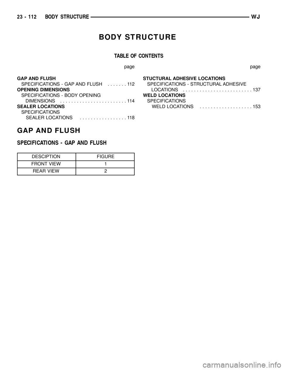
BODY STRUCTURE
TABLE OF CONTENTS
page page
GAP AND FLUSH
SPECIFICATIONS - GAP AND FLUSH.......112
OPENING DIMENSIONS
SPECIFICATIONS - BODY OPENING
DIMENSIONS........................114
SEALER LOCATIONS
SPECIFICATIONS
SEALER LOCATIONS.................118STUCTURAL ADHESIVE LOCATIONS
SPECIFICATIONS - STRUCTURAL ADHESIVE
LOCATIONS.........................137
WELD LOCATIONS
SPECIFICATIONS
WELD LOCATIONS...................153
GAP AND FLUSH
SPECIFICATIONS - GAP AND FLUSH
DESCIPTION FIGURE
FRONT VIEW 1
REAR VIEW 2
23 - 112 BODY STRUCTUREWJ
Page 1987 of 2199
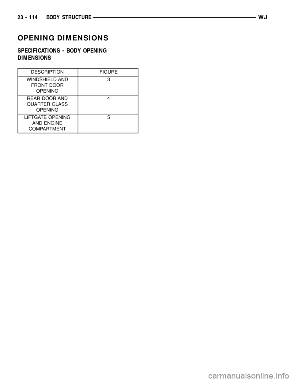
OPENING DIMENSIONS
SPECIFICATIONS - BODY OPENING
DIMENSIONS
DESCRIPTION FIGURE
WINDSHIELD AND
FRONT DOOR
OPENING3
REAR DOOR AND
QUARTER GLASS
OPENING4
LIFTGATE OPENING
AND ENGINE
COMPARTMENT5
23 - 114 BODY STRUCTUREWJ
Page 1991 of 2199
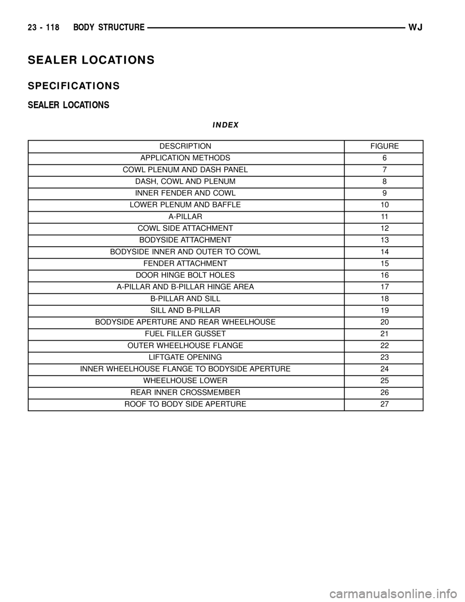
SEALER LOCATIONS
SPECIFICATIONS
SEALER LOCATIONS
INDEX
DESCRIPTION FIGURE
APPLICATION METHODS 6
COWL PLENUM AND DASH PANEL 7
DASH, COWL AND PLENUM 8
INNER FENDER AND COWL 9
LOWER PLENUM AND BAFFLE 10
A-PILLAR 11
COWL SIDE ATTACHMENT 12
BODYSIDE ATTACHMENT 13
BODYSIDE INNER AND OUTER TO COWL 14
FENDER ATTACHMENT 15
DOOR HINGE BOLT HOLES 16
A-PILLAR AND B-PILLAR HINGE AREA 17
B-PILLAR AND SILL 18
SILL AND B-PILLAR 19
BODYSIDE APERTURE AND REAR WHEELHOUSE 20
FUEL FILLER GUSSET 21
OUTER WHEELHOUSE FLANGE 22
LIFTGATE OPENING 23
INNER WHEELHOUSE FLANGE TO BODYSIDE APERTURE 24
WHEELHOUSE LOWER 25
REAR INNER CROSSMEMBER 26
ROOF TO BODY SIDE APERTURE 27
23 - 118 BODY STRUCTUREWJ
Page 2010 of 2199
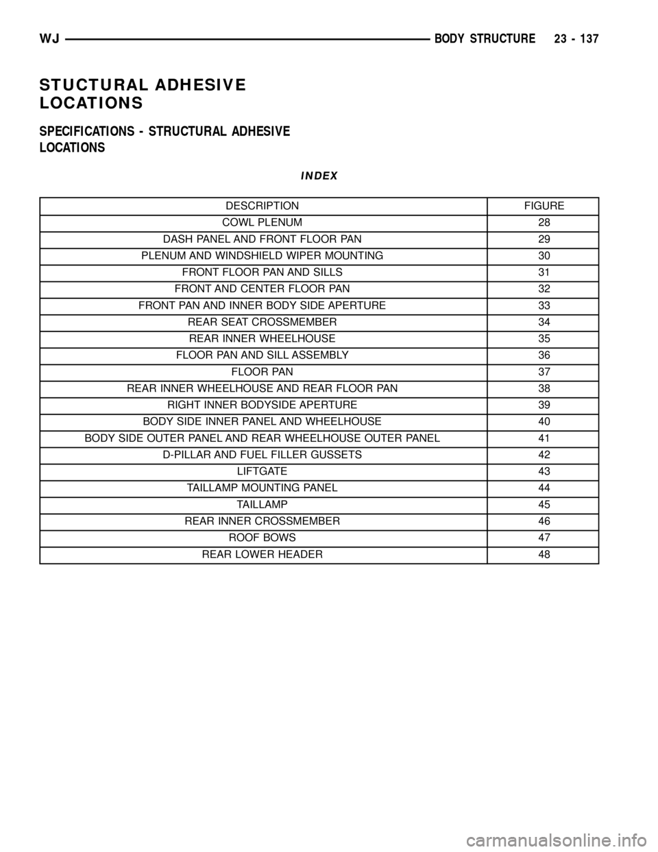
STUCTURAL ADHESIVE
LOCATIONS
SPECIFICATIONS - STRUCTURAL ADHESIVE
LOCATIONS
INDEX
DESCRIPTION FIGURE
COWL PLENUM 28
DASH PANEL AND FRONT FLOOR PAN 29
PLENUM AND WINDSHIELD WIPER MOUNTING 30
FRONT FLOOR PAN AND SILLS 31
FRONT AND CENTER FLOOR PAN 32
FRONT PAN AND INNER BODY SIDE APERTURE 33
REAR SEAT CROSSMEMBER 34
REAR INNER WHEELHOUSE 35
FLOOR PAN AND SILL ASSEMBLY 36
FLOOR PAN 37
REAR INNER WHEELHOUSE AND REAR FLOOR PAN 38
RIGHT INNER BODYSIDE APERTURE 39
BODY SIDE INNER PANEL AND WHEELHOUSE 40
BODY SIDE OUTER PANEL AND REAR WHEELHOUSE OUTER PANEL 41
D-PILLAR AND FUEL FILLER GUSSETS 42
LIFTGATE 43
TAILLAMP MOUNTING PANEL 44
TAILLAMP 45
REAR INNER CROSSMEMBER 46
ROOF BOWS 47
REAR LOWER HEADER 48
WJBODY STRUCTURE 23 - 137
Page 2026 of 2199
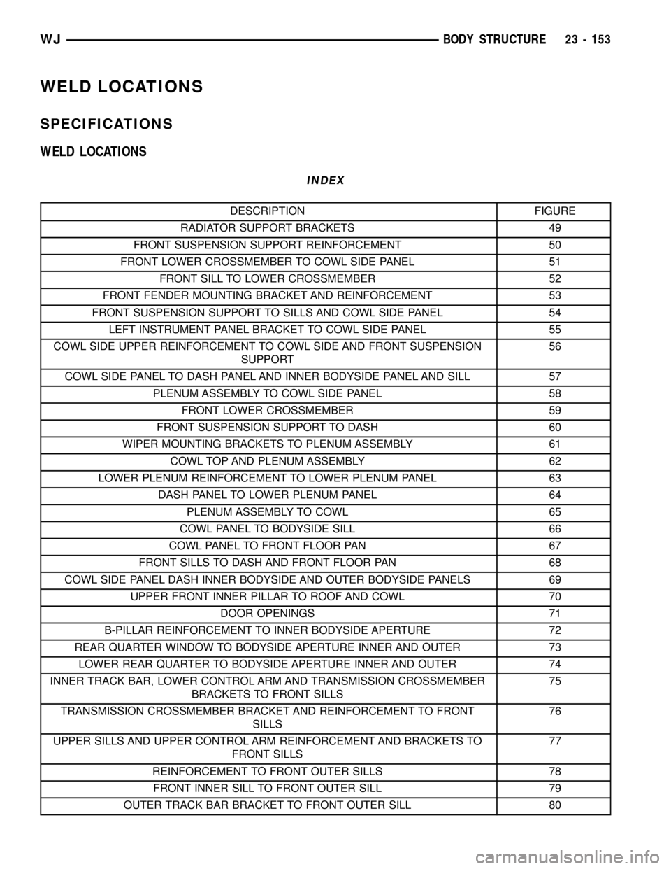
WELD LOCATIONS
SPECIFICATIONS
WELD LOCATIONS
INDEX
DESCRIPTION FIGURE
RADIATOR SUPPORT BRACKETS 49
FRONT SUSPENSION SUPPORT REINFORCEMENT 50
FRONT LOWER CROSSMEMBER TO COWL SIDE PANEL 51
FRONT SILL TO LOWER CROSSMEMBER 52
FRONT FENDER MOUNTING BRACKET AND REINFORCEMENT 53
FRONT SUSPENSION SUPPORT TO SILLS AND COWL SIDE PANEL 54
LEFT INSTRUMENT PANEL BRACKET TO COWL SIDE PANEL 55
COWL SIDE UPPER REINFORCEMENT TO COWL SIDE AND FRONT SUSPENSION
SUPPORT56
COWL SIDE PANEL TO DASH PANEL AND INNER BODYSIDE PANEL AND SILL 57
PLENUM ASSEMBLY TO COWL SIDE PANEL 58
FRONT LOWER CROSSMEMBER 59
FRONT SUSPENSION SUPPORT TO DASH 60
WIPER MOUNTING BRACKETS TO PLENUM ASSEMBLY 61
COWL TOP AND PLENUM ASSEMBLY 62
LOWER PLENUM REINFORCEMENT TO LOWER PLENUM PANEL 63
DASH PANEL TO LOWER PLENUM PANEL 64
PLENUM ASSEMBLY TO COWL 65
COWL PANEL TO BODYSIDE SILL 66
COWL PANEL TO FRONT FLOOR PAN 67
FRONT SILLS TO DASH AND FRONT FLOOR PAN 68
COWL SIDE PANEL DASH INNER BODYSIDE AND OUTER BODYSIDE PANELS 69
UPPER FRONT INNER PILLAR TO ROOF AND COWL 70
DOOR OPENINGS 71
B-PILLAR REINFORCEMENT TO INNER BODYSIDE APERTURE 72
REAR QUARTER WINDOW TO BODYSIDE APERTURE INNER AND OUTER 73
LOWER REAR QUARTER TO BODYSIDE APERTURE INNER AND OUTER 74
INNER TRACK BAR, LOWER CONTROL ARM AND TRANSMISSION CROSSMEMBER
BRACKETS TO FRONT SILLS75
TRANSMISSION CROSSMEMBER BRACKET AND REINFORCEMENT TO FRONT
SILLS76
UPPER SILLS AND UPPER CONTROL ARM REINFORCEMENT AND BRACKETS TO
FRONT SILLS77
REINFORCEMENT TO FRONT OUTER SILLS 78
FRONT INNER SILL TO FRONT OUTER SILL 79
OUTER TRACK BAR BRACKET TO FRONT OUTER SILL 80
WJBODY STRUCTURE 23 - 153