Anti JEEP GRAND CHEROKEE 2003 WJ / 2.G Repair Manual
[x] Cancel search | Manufacturer: JEEP, Model Year: 2003, Model line: GRAND CHEROKEE, Model: JEEP GRAND CHEROKEE 2003 WJ / 2.GPages: 2199, PDF Size: 76.01 MB
Page 876 of 2199
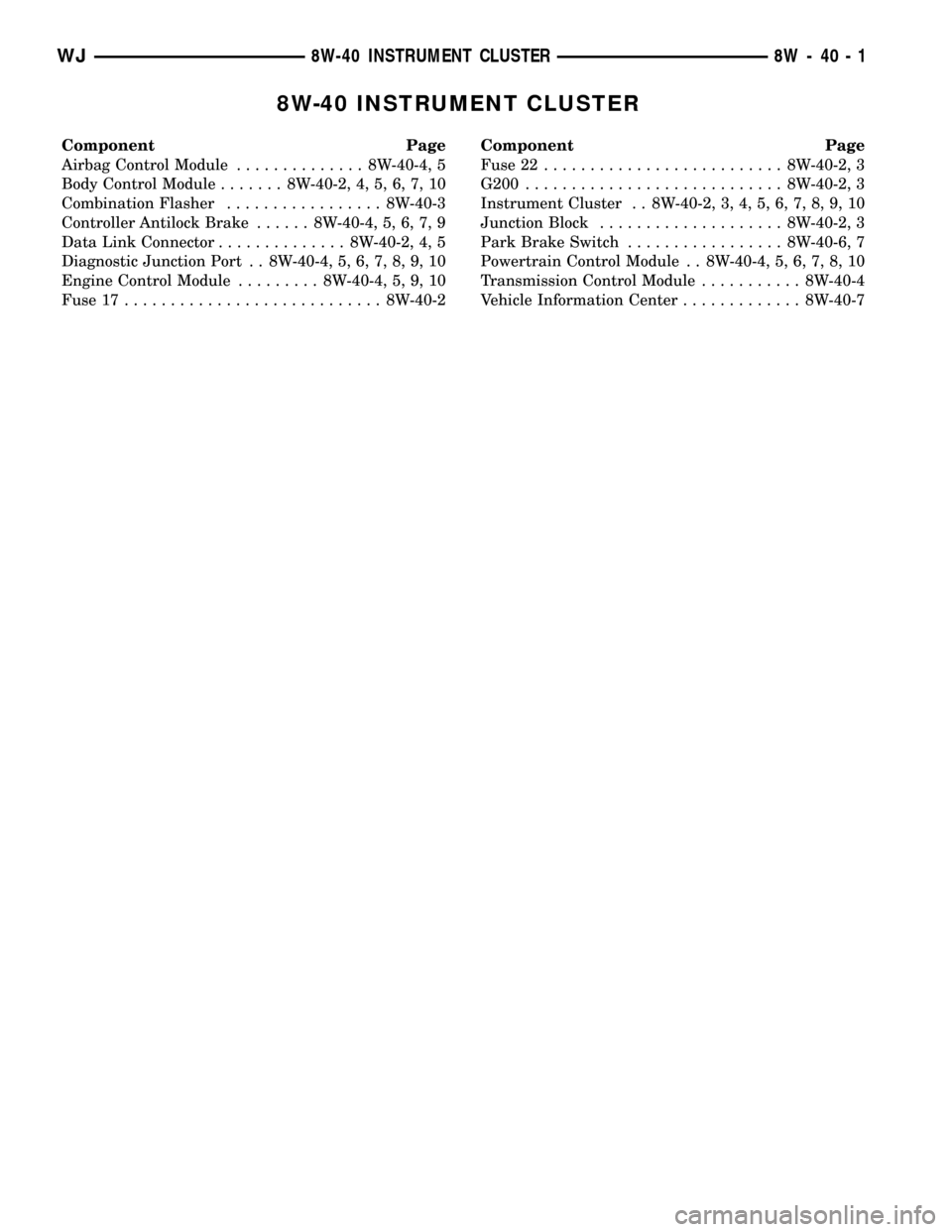
8W-40 INSTRUMENT CLUSTER
Component Page
Airbag Control Module.............. 8W-40-4, 5
Body Control Module....... 8W-40-2, 4, 5, 6, 7, 10
Combination Flasher................. 8W-40-3
Controller Antilock Brake...... 8W-40-4, 5, 6, 7, 9
Data Link Connector.............. 8W-40-2, 4, 5
Diagnostic Junction Port . . 8W-40-4, 5, 6, 7, 8, 9, 10
Engine Control Module......... 8W-40-4, 5, 9, 10
Fuse 17............................ 8W-40-2Component Page
Fuse 22.......................... 8W-40-2, 3
G200............................ 8W-40-2, 3
Instrument Cluster . . 8W-40-2, 3, 4, 5, 6, 7, 8, 9, 10
Junction Block.................... 8W-40-2, 3
Park Brake Switch................. 8W-40-6, 7
Powertrain Control Module . . 8W-40-4, 5, 6, 7, 8, 10
Transmission Control Module........... 8W-40-4
Vehicle Information Center............. 8W-40-7
WJ8W-40 INSTRUMENT CLUSTER 8W - 40 - 1
Page 970 of 2199
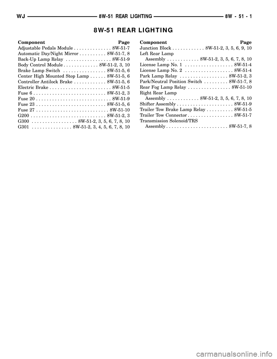
8W-51 REAR LIGHTING
Component Page
Adjustable Pedals Module.............. 8W-51-7
Automatic Day/Night Mirror.......... 8W-51-7, 8
Back-Up Lamp Relay................. 8W-51-9
Body Control Module............. 8W-51-2, 3, 10
Brake Lamp Switch................ 8W-51-5, 6
Center High Mounted Stop Lamp...... 8W-51-5, 6
Controller Antilock Brake............ 8W-51-5, 6
Electric Brake....................... 8W-51-5
Fuse 6........................... 8W-51-2, 3
Fuse 20............................ 8W-51-9
Fuse 23.......................... 8W-51-5, 6
Fuse 27........................... 8W-51-10
G200............................ 8W-51-2, 3
G300................. 8W-51-2, 3, 5, 6, 7, 8, 10
G301............... 8W-51-2, 3, 4, 5, 6, 7, 8, 10Component Page
Junction Block............ 8W-51-2, 3, 5, 6, 9, 10
Left Rear Lamp
Assembly............ 8W-51-2, 3, 5, 6, 7, 8, 10
License Lamp No. 1.................. 8W-51-4
License Lamp No. 2.................. 8W-51-4
Park Lamp Relay.................. 8W-51-2, 3
Park/Neutral Position Switch......... 8W-51-7, 8
Rear Fog Lamp Relay................ 8W-51-10
Right Rear Lamp
Assembly............ 8W-51-2, 3, 5, 6, 7, 8, 10
Shifter Assembly..................... 8W-51-9
Trailer Tow Brake Lamp Relay.......... 8W-51-5
Trailer Tow Connector................. 8W-51-7
Transmission Solenoid/TRS
Assembly....................... 8W-51-7, 8
WJ8W-51 REAR LIGHTING 8W - 51 - 1
Page 1049 of 2199
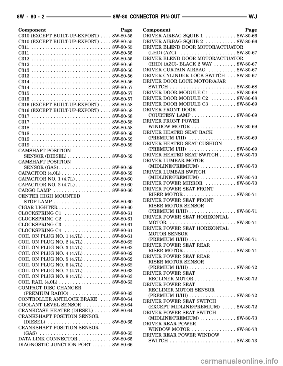
Component Page
C310 (EXCEPT BUILT-UP-EXPORT).... 8W-80-55
C310 (EXCEPT BUILT-UP-EXPORT).... 8W-80-55
C311 ............................. 8W-80-55
C311 ............................. 8W-80-55
C312............................. 8W-80-55
C312............................. 8W-80-56
C313............................. 8W-80-56
C313............................. 8W-80-56
C314............................. 8W-80-56
C314............................. 8W-80-57
C315............................. 8W-80-57
C315............................. 8W-80-57
C316 (EXCEPT BUILT-UP-EXPORT).... 8W-80-58
C316 (EXCEPT BUILT-UP-EXPORT).... 8W-80-58
C317............................. 8W-80-58
C317............................. 8W-80-58
C318............................. 8W-80-58
C318............................. 8W-80-59
C319............................. 8W-80-59
C319............................. 8W-80-59
CAMSHAFT POSITION
SENSOR (DIESEL)................ 8W-80-59
CAMSHAFT POSITION
SENSOR (GAS)................... 8W-80-59
CAPACITOR (4.0L).................. 8W-80-59
CAPACITOR NO. 1 (4.7L)............. 8W-80-60
CAPACITOR NO. 2 (4.7L)............. 8W-80-60
CARGO LAMP..................... 8W-80-60
CENTER HIGH MOUNTED
STOP LAMP..................... 8W-80-60
CIGAR LIGHTER................... 8W-80-60
CLOCKSPRING C1................. 8W-80-61
CLOCKSPRING C2................. 8W-80-61
CLOCKSPRING C3................. 8W-80-61
CLOCKSPRING C4................. 8W-80-61
COIL ON PLUG NO. 1 (4.7L).......... 8W-80-61
COIL ON PLUG NO. 2 (4.7L).......... 8W-80-62
COIL ON PLUG NO. 3 (4.7L).......... 8W-80-62
COIL ON PLUG NO. 4 (4.7L).......... 8W-80-62
COIL ON PLUG NO. 5 (4.7L).......... 8W-80-62
COIL ON PLUG NO. 6 (4.7L).......... 8W-80-62
COIL ON PLUG NO. 7 (4.7L).......... 8W-80-63
COIL ON PLUG NO. 8 (4.7L).......... 8W-80-63
COIL RAIL (4.0L)................... 8W-80-63
COMPACT DISC CHANGER
(PREMIUM RADIO)............... 8W-80-63
CONTROLLER ANTILOCK BRAKE.... 8W-80-64
COOLANT LEVEL SENSOR.......... 8W-80-64
CRANKCASE HEATER (DIESEL)...... 8W-80-64
CRANKSHAFT POSITION SENSOR
(DIESEL)....................... 8W-80-65
CRANKSHAFT POSITION SENSOR
(GAS).......................... 8W-80-65
DATA LINK CONNECTOR............ 8W-80-65
DIAGNOSTIC JUNCTION PORT....... 8W-80-66Component Page
DRIVER AIRBAG SQUIB 1........... 8W-80-66
DRIVER AIRBAG SQUIB 2........... 8W-80-66
DRIVER BLEND DOOR MOTOR/ACTUATOR
(LHD) (AZC)..................... 8W-80-67
DRIVER BLEND DOOR MOTOR/ACTUATOR
(RHD) (AZC)- BLACK 2 WAY........ 8W-80-67
DRIVER CURTAIN AIRBAG.......... 8W-80-67
DRIVER CYLINDER LOCK SWITCH . . . 8W-80-67
DRIVER DOOR LOCK MOTOR/AJAR
SWITCH........................ 8W-80-68
DRIVER DOOR MODULE C1......... 8W-80-68
DRIVER DOOR MODULE C2......... 8W-80-68
DRIVER DOOR MODULE C3......... 8W-80-69
DRIVER FRONT DOOR
COURTESY LAMP................ 8W-80-69
DRIVER FRONT POWER
WINDOW MOTOR................ 8W-80-69
DRIVER HEATED SEAT BACK
(PREMIUM I/III)................. 8W-80-69
DRIVER HEATED SEAT CUSHION
(PREMIUM I/III)................. 8W-80-69
DRIVER HEATED SEAT SWITCH...... 8W-80-70
DRIVER LUMBAR MOTOR
(MIDLINE/PREMIUM)............. 8W-80-70
DRIVER LUMBAR SWITCH
(MIDLINE/PREMIUM)............. 8W-80-70
DRIVER POWER MIRROR........... 8W-80-70
DRIVER POWER SEAT FRONT
RISER MOTOR................... 8W-80-71
DRIVER POWER SEAT FRONT
RISER MOTOR SENSOR
(PREMIUM II/III)................. 8W-80-71
DRIVER POWER SEAT HORIZONTAL
MOTOR........................ 8W-80-71
DRIVER POWER SEAT HORIZONTAL
MOTOR SENSOR
(PREMIUM II/III)................. 8W-80-71
DRIVER POWER SEAT REAR
RISER MOTOR................... 8W-80-71
DRIVER POWER SEAT REAR
RISER MOTOR SENSOR
(PREMIUM II/III)................. 8W-80-72
DRIVER POWER SEAT
RECLINER MOTOR............... 8W-80-72
DRIVER POWER SEAT
RECLINER MOTOR SENSOR
(PREMIUM II/III)................. 8W-80-72
DRIVER POWER SEAT SWITCH
(EXCEPT MIDLINE/PREMIUM)..... 8W-80-72
DRIVER POWER SEAT SWITCH
(MIDLINE/PREMIUM)............. 8W-80-73
DRIVER REAR POWER
WINDOW MOTOR................ 8W-80-73
DRIVER REAR POWER WINDOW
SWITCH........................ 8W-80-73
8W - 80 - 2 8W-80 CONNECTOR PIN-OUTWJ
Page 1111 of 2199
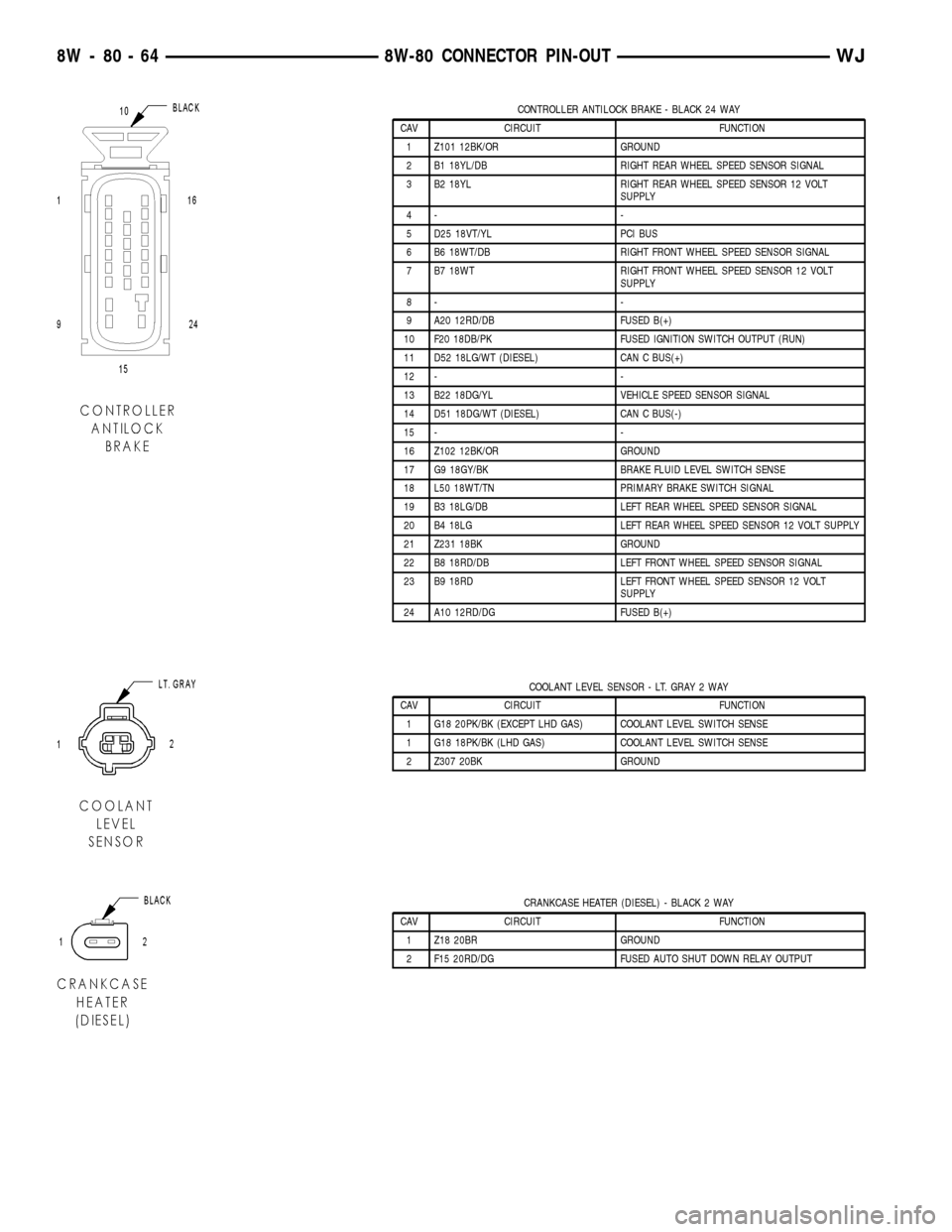
CONTROLLER ANTILOCK BRAKE - BLACK 24 WAY
CAV CIRCUIT FUNCTION
1 Z101 12BK/OR GROUND
2 B1 18YL/DB RIGHT REAR WHEEL SPEED SENSOR SIGNAL
3 B2 18YL RIGHT REAR WHEEL SPEED SENSOR 12 VOLT
SUPPLY
4- -
5 D25 18VT/YL PCI BUS
6 B6 18WT/DB RIGHT FRONT WHEEL SPEED SENSOR SIGNAL
7 B7 18WT RIGHT FRONT WHEEL SPEED SENSOR 12 VOLT
SUPPLY
8- -
9 A20 12RD/DB FUSED B(+)
10 F20 18DB/PK FUSED IGNITION SWITCH OUTPUT (RUN)
11 D52 18LG/WT (DIESEL) CAN C BUS(+)
12 - -
13 B22 18DG/YL VEHICLE SPEED SENSOR SIGNAL
14 D51 18DG/WT (DIESEL) CAN C BUS(-)
15 - -
16 Z102 12BK/OR GROUND
17 G9 18GY/BK BRAKE FLUID LEVEL SWITCH SENSE
18 L50 18WT/TN PRIMARY BRAKE SWITCH SIGNAL
19 B3 18LG/DB LEFT REAR WHEEL SPEED SENSOR SIGNAL
20 B4 18LG LEFT REAR WHEEL SPEED SENSOR 12 VOLT SUPPLY
21 Z231 18BK GROUND
22 B8 18RD/DB LEFT FRONT WHEEL SPEED SENSOR SIGNAL
23 B9 18RD LEFT FRONT WHEEL SPEED SENSOR 12 VOLT
SUPPLY
24 A10 12RD/DG FUSED B(+)
COOLANT LEVEL SENSOR - LT. GRAY 2 WAY
CAV CIRCUIT FUNCTION
1 G18 20PK/BK (EXCEPT LHD GAS) COOLANT LEVEL SWITCH SENSE
1 G18 18PK/BK (LHD GAS) COOLANT LEVEL SWITCH SENSE
2 Z307 20BK GROUND
CRANKCASE HEATER (DIESEL) - BLACK 2 WAY
CAV CIRCUIT FUNCTION
1 Z18 20BR GROUND
2 F15 20RD/DG FUSED AUTO SHUT DOWN RELAY OUTPUT
8W - 80 - 64 8W-80 CONNECTOR PIN-OUTWJ
Page 1179 of 2199
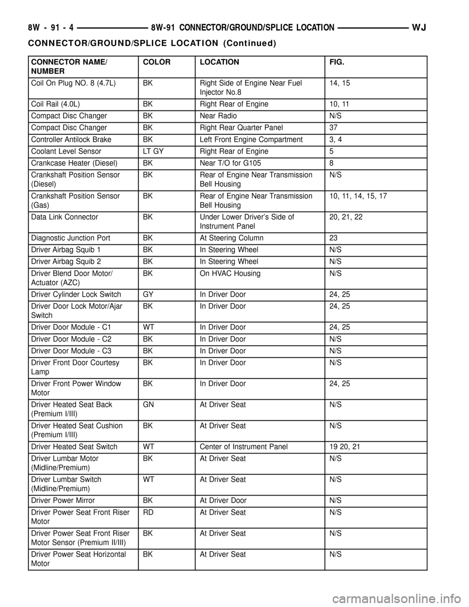
CONNECTOR NAME/
NUMBERCOLOR LOCATION FIG.
Coil On Plug NO. 8 (4.7L) BK Right Side of Engine Near Fuel
Injector No.814, 15
Coil Rail (4.0L) BK Right Rear of Engine 10, 11
Compact Disc Changer BK Near Radio N/S
Compact Disc Changer BK Right Rear Quarter Panel 37
Controller Antilock Brake BK Left Front Engine Compartment 3, 4
Coolant Level Sensor LT GY Right Rear of Engine 5
Crankcase Heater (Diesel) BK Near T/O for G105 8
Crankshaft Position Sensor
(Diesel)BK Rear of Engine Near Transmission
Bell HousingN/S
Crankshaft Position Sensor
(Gas)BK Rear of Engine Near Transmission
Bell Housing10, 11, 14, 15, 17
Data Link Connector BK Under Lower Driver's Side of
Instrument Panel20, 21, 22
Diagnostic Junction Port BK At Steering Column 23
Driver Airbag Squib 1 BK In Steering Wheel N/S
Driver Airbag Squib 2 BK In Steering Wheel N/S
Driver Blend Door Motor/
Actuator (AZC)BK On HVAC Housing N/S
Driver Cylinder Lock Switch GY In Driver Door 24, 25
Driver Door Lock Motor/Ajar
SwitchBK In Driver Door 24, 25
Driver Door Module - C1 WT In Driver Door 24, 25
Driver Door Module - C2 BK In Driver Door N/S
Driver Door Module - C3 BK In Driver Door N/S
Driver Front Door Courtesy
LampBK In Driver Door N/S
Driver Front Power Window
MotorBK In Driver Door 24, 25
Driver Heated Seat Back
(Premium I/III)GN At Driver Seat N/S
Driver Heated Seat Cushion
(Premium I/III)BK At Driver Seat N/S
Driver Heated Seat Switch WT Center of Instrument Panel 19 20, 21
Driver Lumbar Motor
(Midline/Premium)BK At Driver Seat N/S
Driver Lumbar Switch
(Midline/Premium)WT At Driver Seat N/S
Driver Power Mirror BK At Driver Door N/S
Driver Power Seat Front Riser
MotorRD At Driver Seat N/S
Driver Power Seat Front Riser
Motor Sensor (Premium II/III)BK At Driver Seat N/S
Driver Power Seat Horizontal
MotorBK At Driver Seat N/S
8W - 91 - 4 8W-91 CONNECTOR/GROUND/SPLICE LOCATIONWJ
CONNECTOR/GROUND/SPLICE LOCATION (Continued)
Page 1180 of 2199
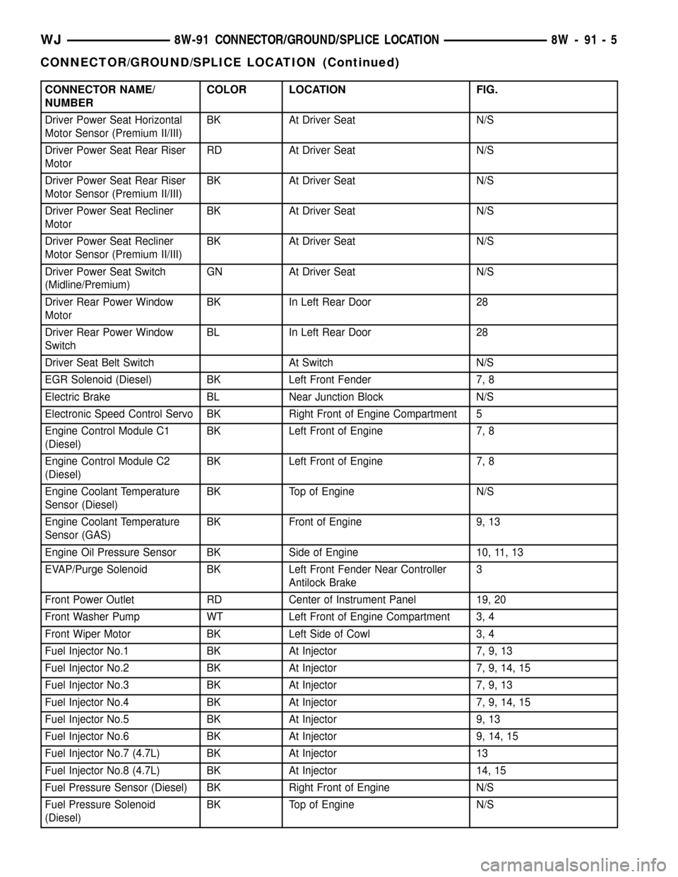
CONNECTOR NAME/
NUMBERCOLOR LOCATION FIG.
Driver Power Seat Horizontal
Motor Sensor (Premium II/III)BK At Driver Seat N/S
Driver Power Seat Rear Riser
MotorRD At Driver Seat N/S
Driver Power Seat Rear Riser
Motor Sensor (Premium II/III)BK At Driver Seat N/S
Driver Power Seat Recliner
MotorBK At Driver Seat N/S
Driver Power Seat Recliner
Motor Sensor (Premium II/III)BK At Driver Seat N/S
Driver Power Seat Switch
(Midline/Premium)GN At Driver Seat N/S
Driver Rear Power Window
MotorBK In Left Rear Door 28
Driver Rear Power Window
SwitchBL In Left Rear Door 28
Driver Seat Belt Switch At Switch N/S
EGR Solenoid (Diesel) BK Left Front Fender 7, 8
Electric Brake BL Near Junction Block N/S
Electronic Speed Control Servo BK Right Front of Engine Compartment 5
Engine Control Module C1
(Diesel)BK Left Front of Engine 7, 8
Engine Control Module C2
(Diesel)BK Left Front of Engine 7, 8
Engine Coolant Temperature
Sensor (Diesel)BK Top of Engine N/S
Engine Coolant Temperature
Sensor (GAS)BK Front of Engine 9, 13
Engine Oil Pressure Sensor BK Side of Engine 10, 11, 13
EVAP/Purge Solenoid BK Left Front Fender Near Controller
Antilock Brake3
Front Power Outlet RD Center of Instrument Panel 19, 20
Front Washer Pump WT Left Front of Engine Compartment 3, 4
Front Wiper Motor BK Left Side of Cowl 3, 4
Fuel Injector No.1 BK At Injector 7, 9, 13
Fuel Injector No.2 BK At Injector 7, 9, 14, 15
Fuel Injector No.3 BK At Injector 7, 9, 13
Fuel Injector No.4 BK At Injector 7, 9, 14, 15
Fuel Injector No.5 BK At Injector 9, 13
Fuel Injector No.6 BK At Injector 9, 14, 15
Fuel Injector No.7 (4.7L) BK At Injector 13
Fuel Injector No.8 (4.7L) BK At Injector 14, 15
Fuel Pressure Sensor (Diesel) BK Right Front of Engine N/S
Fuel Pressure Solenoid
(Diesel)BK Top of Engine N/S
WJ8W-91 CONNECTOR/GROUND/SPLICE LOCATION 8W - 91 - 5
CONNECTOR/GROUND/SPLICE LOCATION (Continued)
Page 1188 of 2199
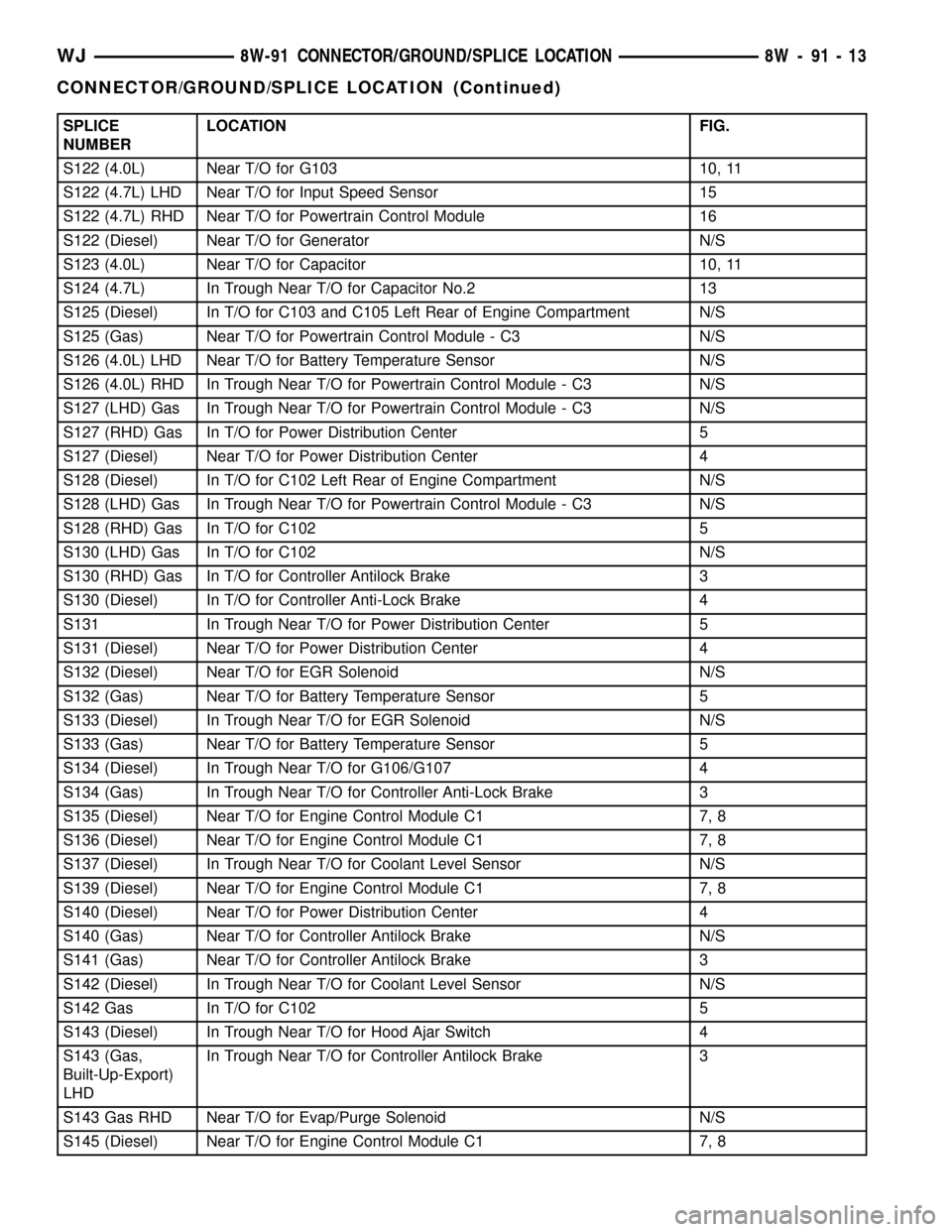
SPLICE
NUMBERLOCATION FIG.
S122 (4.0L) Near T/O for G103 10, 11
S122 (4.7L) LHD Near T/O for Input Speed Sensor 15
S122 (4.7L) RHD Near T/O for Powertrain Control Module 16
S122 (Diesel) Near T/O for Generator N/S
S123 (4.0L) Near T/O for Capacitor 10, 11
S124 (4.7L) In Trough Near T/O for Capacitor No.2 13
S125 (Diesel) In T/O for C103 and C105 Left Rear of Engine Compartment N/S
S125 (Gas) Near T/O for Powertrain Control Module - C3 N/S
S126 (4.0L) LHD Near T/O for Battery Temperature Sensor N/S
S126 (4.0L) RHD In Trough Near T/O for Powertrain Control Module - C3 N/S
S127 (LHD) Gas In Trough Near T/O for Powertrain Control Module - C3 N/S
S127 (RHD) Gas In T/O for Power Distribution Center 5
S127 (Diesel) Near T/O for Power Distribution Center 4
S128 (Diesel) In T/O for C102 Left Rear of Engine Compartment N/S
S128 (LHD) Gas In Trough Near T/O for Powertrain Control Module - C3 N/S
S128 (RHD) Gas In T/O for C102 5
S130 (LHD) Gas In T/O for C102 N/S
S130 (RHD) Gas In T/O for Controller Antilock Brake 3
S130 (Diesel) In T/O for Controller Anti-Lock Brake 4
S131 In Trough Near T/O for Power Distribution Center 5
S131 (Diesel) Near T/O for Power Distribution Center 4
S132 (Diesel) Near T/O for EGR Solenoid N/S
S132 (Gas) Near T/O for Battery Temperature Sensor 5
S133 (Diesel) In Trough Near T/O for EGR Solenoid N/S
S133 (Gas) Near T/O for Battery Temperature Sensor 5
S134 (Diesel) In Trough Near T/O for G106/G107 4
S134 (Gas) In Trough Near T/O for Controller Anti-Lock Brake 3
S135 (Diesel) Near T/O for Engine Control Module C1 7, 8
S136 (Diesel) Near T/O for Engine Control Module C1 7, 8
S137 (Diesel) In Trough Near T/O for Coolant Level Sensor N/S
S139 (Diesel) Near T/O for Engine Control Module C1 7, 8
S140 (Diesel) Near T/O for Power Distribution Center 4
S140 (Gas) Near T/O for Controller Antilock Brake N/S
S141 (Gas) Near T/O for Controller Antilock Brake 3
S142 (Diesel) In Trough Near T/O for Coolant Level Sensor N/S
S142 Gas In T/O for C102 5
S143 (Diesel) In Trough Near T/O for Hood Ajar Switch 4
S143 (Gas,
Built-Up-Export)
LHDIn Trough Near T/O for Controller Antilock Brake 3
S143 Gas RHD Near T/O for Evap/Purge Solenoid N/S
S145 (Diesel) Near T/O for Engine Control Module C1 7, 8
WJ8W-91 CONNECTOR/GROUND/SPLICE LOCATION 8W - 91 - 13
CONNECTOR/GROUND/SPLICE LOCATION (Continued)
Page 1189 of 2199
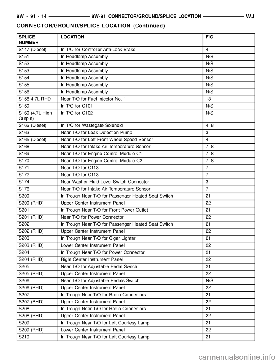
SPLICE
NUMBERLOCATION FIG.
S147 (Diesel) In T/O for Controller Anti-Lock Brake 4
S151 In Headlamp Assembly N/S
S152 In Headlamp Assembly N/S
S153 In Headlamp Assembly N/S
S154 In Headlamp Assembly N/S
S155 In Headlamp Assembly N/S
S156 In Headlamp Assembly N/S
S158 4.7L RHD Near T/O for Fuel Injector No. 1 13
S159 In T/O for C101 N/S
S160 (4.7L High
Output)In T/O for C102 N/S
S162 (Diesel) In T/O for Wastegate Solenoid 4, 8
S163 Near T/O for Leak Detection Pump 3
S165 (Diesel) Near T/O for Left Front Wheel Speed Sensor 4
S168 Near T/O for Intake Air Temperature Sensor 7, 8
S169 Near T/O for Engine Control Module C1 7, 8
S170 Near T/O for Engine Control Module C2 7, 8
S171 Near T/O for C113 7
S172 Near T/O for C113 7
S174 Near Washer Fluid Level Switch Connector 3
S176 Near T/O for Intake Air Temperature Sensor 7
S200 In Trough Near T/O for Passenger Heated Seat Switch 21
S200 (RHD) Upper Center Instrument Panel 22
S201 In Trough Near T/O for Front Power Outlet 21
S201 (RHD) Near T/O for Power Connector 22
S202 In Trough Near T/O for Passenger Heated Seat Switch 21
S202 (RHD) Upper Center Instrument Panel 22
S203 In Trough Near T/O for Cigar Lighter 21
S203 (RHD) Lower Center Instrument Panel 22
S204 In Trough Near T/O for Power Connector 21
S204 (RHD) Right Center Instrument Panel 22
S205 Near T/O for Adjustable Pedal Switch 21
S205 (RHD) Upper Center Instrument Panel 22
S206 Near T/O for Adjustable Pedals Switch N/S
S206 (RHD) Upper Center Instrument Panel 22
S207 In Trough Near T/O for Radio Connectors 21
S207 (RHD) Upper Center Instrument Panel 22
S208 In Trough Near T/O for Radio Connectors 21
S208 (RHD) Upper Center Instrument Panel 22
S209 In Trough Near T/O for Left Courtesy Lamp 21
S209 (RHD) Lower Center Instrument Panel 22
S210 In Trough Near T/O for Left Courtesy Lamp 21
8W - 91 - 14 8W-91 CONNECTOR/GROUND/SPLICE LOCATIONWJ
CONNECTOR/GROUND/SPLICE LOCATION (Continued)
Page 1366 of 2199
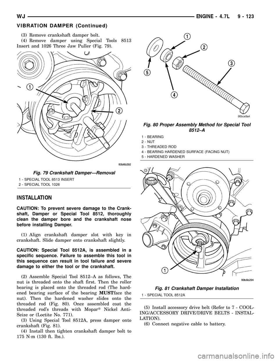
(3) Remove crankshaft damper bolt.
(4) Remove damper using Special Tools 8513
Insert and 1026 Three Jaw Puller (Fig. 79).
INSTALLATION
CAUTION: To prevent severe damage to the Crank-
shaft, Damper or Special Tool 8512, thoroughly
clean the damper bore and the crankshaft nose
before installing Damper.
(1) Align crankshaft damper slot with key in
crankshaft. Slide damper onto crankshaft slightly.
CAUTION: Special Tool 8512A, is assembled in a
specific sequence. Failure to assemble this tool in
this sequence can result in tool failure and severe
damage to either the tool or the crankshaft.
(2) Assemble Special Tool 8512±A as follows, The
nut is threaded onto the shaft first. Then the roller
bearing is placed onto the threaded rod (The hard-
ened bearing surface of the bearingMUSTface the
nut). Then the hardened washer slides onto the
threaded rod (Fig. 80). Once assembled coat the
threaded rod's threads with MopartNickel Anti-
Seize or (Loctite No. 771).
(3) Using Special Tool 8512A, press damper onto
crankshaft (Fig. 81).
(4) Install then tighten crankshaft damper bolt to
175 N´m (130 ft. lbs.).(5) Install accessory drive belt (Refer to 7 - COOL-
ING/ACCESSORY DRIVE/DRIVE BELTS - INSTAL-
LATION).
(6) Connect negative cable to battery.
Fig. 79 Crankshaft DamperÐRemoval
1 - SPECIAL TOOL 8513 INSERT
2 - SPECIAL TOOL 1026
Fig. 80 Proper Assembly Method for Special Tool
8512±A
1 - BEARING
2 - NUT
3 - THREADED ROD
4 - BEARING HARDENED SURFACE (FACING NUT)
5 - HARDENED WASHER
Fig. 81 Crankshaft Damper Installation
1 - SPECIAL TOOL 8512A
WJENGINE - 4.7L 9 - 123
VIBRATION DAMPER (Continued)
Page 1384 of 2199
INSPECTION
(1) Inspect the exhaust manifold for cracks in the
mating surface and at every mounting bolt hole.
(2) Using a straight edge and a feeler gauge, check
the mating surface for warp and twist.
(3) Inspect the manifold to exhaust pipe mating
surface for cracks, gouges, or other damage that
would prevent sealing.
INSTALLATION
(1) Install exhaust manifold and gasket from below
engine compartment.
(2) Install lower exhaust manifold fasteners. DO
NOT tighten until all fasteners are in place.
(3) Lower vehicle and install upper exhaust mani-
fold fasteners. Tighten all manifold bolts starting at
center and working outward to 25 N´m (18 ft. lbs.).
CAUTION: Over tightening heat shield fasteners,
may cause shield to distort and/or crack.
(4) Install exhaust manifold heat shield. Tighten
fasteners to 8 N´m (72 in. lbs.), then loosen 45
degrees.
(5) Install starter and fasteners.
(6) Connect exhaust pipe to manifold.
(7) Connect heater hoses at engine.
(8) Install fastener attaching A/C accumulator.
(9) Install A/C compressor and fasteners.
(10) Install accessory drive belt (Refer to 7 -
COOLING/ACCESSORY DRIVE/DRIVE BELTS -
INSTALLATION).
(11) Install washer bottle and battery tray assem-
bly.
(12) Install PDC.
(13) Install battery and connect cables.
(14) Fill cooling system (Refer to 7 - COOLING -
STANDARD PROCEDURE).
VALVE TIMING
DESCRIPTION - TIMING DRIVE SYSTEM
The timing drive system has been designed to pro-
vide quiet performance and reliability to support a
non-free wheelingengine. Specifically the intake
valves are non-free wheeling and can be easily dam-
aged with forceful engine rotation if camshaft-to-
crankshaft timing is incorrect. The timing drive
system consists of a primary chain and two second-
ary timing chain drives (Fig. 109).
OPERATION - TIMING DRIVE SYSTEM
The primary timing chain is a single inverted tooth
type. The primary chain drives the large fifty tooth
idler sprocket directly from a 25 tooth crankshaftsprocket. Primary chain motion is controlled by a
pivoting leaf spring tensioner arm and a fixed guide.
The arm and the guide both use nylon plastic wear
faces for low friction and long wear. The primary
chain receives oil splash lubrication from the second-
ary chain drive and oil pump leakage. The idler
sprocket assembly connects the primary and second-
ary chain drives. The idler sprocket assembly con-
sists of two integral thirty tooth sprockets and a fifty
tooth sprocket that is splined to the assembly. The
spline joint is a non ± serviceable press fit anti rattle
type. A spiral ring is installed on the outboard side of
the fifty tooth sprocket to prevent spline disengage-
ment. The idler sprocket assembly spins on a station-
ary idler shaft. The idler shaft is press-fit into the
cylinder block. A large washer on the idler shaft bolt
and the rear flange of the idler shaft are used to con-
trol sprocket thrust movement. Pressurized oil is
routed through the center of the idler shaft to pro-
vide lubrication for the two bushings used in the
idler sprocket assembly.
There are two secondary drive chains, both are
inverted tooth type, one to drive the camshaft in each
SOHC cylinder head. There are no shaft speed
changes in the secondary chain drive system. Each
secondary chain drives a thirty tooth cam sprocket
directly from the thirty tooth sprocket on the idler
sprocket assembly. A fixed chain guide and a hydrau-
lic oil damped tensioner are used to maintain tension
in each secondary chain system. The hydraulic ten-
sioners for the secondary chain systems are fed pres-
surized oil from oil reservoir pockets in the block.
Each tensioner also has a mechanical ratchet system
that limits chain slack if the tensioner piston bleeds
down after engine shut down. The tensioner arms
and guides also utilize nylon wear faces for low fric-
tion and long wear. The secondary timing chains
receive lubrication from a small orifice in the ten-
sioners. This orifice is protected from clogging by a
fine mesh screen which is located on the back of the
hydraulic tensioners.
STANDARD PROCEDURE
STANDARD PROCEDURE - ENGINE TIMING -
VERIFICATION
CAUTION: The 4.7L is a non free-wheeling design
engine. Therefore, correct engine timing is critical.
NOTE: Components referred to as left hand or right
hand are as viewed from the drivers position inside
the vehicle.
WJENGINE - 4.7L 9 - 141
EXHAUST MANIFOLD - RIGHT (Continued)