contents JEEP GRAND CHEROKEE 2003 WJ / 2.G Repair Manual
[x] Cancel search | Manufacturer: JEEP, Model Year: 2003, Model line: GRAND CHEROKEE, Model: JEEP GRAND CHEROKEE 2003 WJ / 2.GPages: 2199, PDF Size: 76.01 MB
Page 1304 of 2199

ENGINE - 4.7L
TABLE OF CONTENTS
page page
ENGINE - 4.7L
DESCRIPTIONÐ4.7L ENGINE.............63
DIAGNOSIS AND TESTING
DIAGNOSIS AND TESTING - ENGINE
DIAGNOSIS - INTRODUCTION...........64
DIAGNOSIS AND TESTING - ENGINE
DIAGNOSIS - PERFORMANCE...........65
DIAGNOSIS AND TESTING - ENGINE
DIAGNOSIS - MECHANICAL.............66
DIAGNOSIS AND TESTING - ENGINE
DIAGNOSIS - LUBRICATION.............67
DIAGNOSIS AND TESTING - CYLINDER
COMPRESSION PRESSURE.............68
DIAGNOSIS AND TESTING - CYLINDER
COMBUSTION PRESSURE LEAKAGE......69
STANDARD PROCEDURE
STANDARD PROCEDURE - REPAIR
DAMAGED OR WORN THREADS.........70
STANDARD PROCEDURE - FORM-IN-
PLACE GASKETS AND SEALERS.........70
STANDARD PROCEDURE - ENGINE
GASKET SURFACE PREPARATION........70
STANDARD PROCEDURE - ENGINE CORE
AND OIL GALLERY PLUGS..............71
REMOVAL.............................71
INSTALLATION.........................73
SPECIFICATIONS
4.7L ENGINE.........................74
SPECIFICATIONS - 4.7L H.O. ENGINE.....77
TORQUE............................79
SPECIAL TOOLS
4.7L ENGINE.........................80
AIR CLEANER ELEMENT
REMOVAL - 4.7L........................83
INSTALLATION - 4.7L....................83
AIR CLEANER HOUSING
REMOVAL - 4.7L........................84
INSTALLATION - 4.7L....................84
CYLINDER HEAD - LEFT
DESCRIPTION
DESCRIPTION - CYLINDER HEAD........84
DESCRIPTION - VALVE GUIDES..........84
DIAGNOSIS AND TESTING
DIAGNOSIS AND TESTING - HYDRAULIC
LASH ADJUSTER.....................84
DIAGNOSIS AND TESTINGÐCYLINDER
HEAD GASKET.......................85
REMOVAL.............................85
CLEANING............................86
INSPECTION..........................87INSTALLATION.........................87
CAMSHAFT(S) - LEFT
DESCRIPTION.........................88
REMOVAL.............................89
INSTALLATION.........................90
CYLINDER HEAD COVER(S) - LEFT
DESCRIPTION.........................93
REMOVAL - LEFT SIDE..................93
CLEANING............................93
INSTALLATIONÐLEFT SIDE...............93
INTAKE/EXHAUST VALVES & SEATS
DESCRIPTION.........................94
STANDARD PROCEDUREÐREFACING......94
REMOVAL.............................94
INSTALLATION.........................95
ROCKER ARM / ADJUSTER ASSEMBLY
DESCRIPTION.........................96
REMOVAL.............................96
INSTALLATION.........................96
VALVE SPRINGS
DESCRIPTION.........................97
VALVE STEM SEALS
DESCRIPTION.........................97
CYLINDER HEAD - RIGHT
DESCRIPTION
DESCRIPTION - CYLINDER HEAD........97
DESCRIPTION - VALVE GUIDES..........97
DIAGNOSIS AND TESTING
DIAGNOSIS AND TESTINGÐCYLINDER
HEAD GASKET.......................97
DIAGNOSIS AND TESTING - HYDRAULIC
LASH ADJUSTER.....................98
REMOVAL.............................98
CLEANING............................99
INSPECTION..........................99
INSTALLATION.........................99
CAMSHAFT(S) - RIGHT
DESCRIPTION........................100
REMOVAL............................100
INSTALLATION........................102
CYLINDER HEAD COVER(S) - RIGHT
DESCRIPTION........................104
REMOVAL - RIGHT SIDE................104
CLEANING...........................104
INSTALLATION - RIGHT SIDE.............104
INTAKE/EXHAUST VALVES & SEATS
DESCRIPTION........................104
STANDARD PROCEDUREÐREFACING.....105
REMOVAL............................105
INSTALLATION........................106
WJENGINE - 4.7L 9 - 61
Page 1398 of 2199

EXHAUST SYSTEM
TABLE OF CONTENTS
page page
EXHAUST SYSTEM
DESCRIPTION - EXHAUST SYSTEM.........1
DIAGNOSIS AND TESTING - EXHAUST
SYSTEM.............................3
SPECIFICATIONS
TORQUE.............................3
CATALYTIC CONVERTER - 4.0L
DESCRIPTION - CATALYTIC CONVERTER
4.0L ENGINE..........................4
REMOVAL.............................4
INSPECTION...........................5
INSTALLATION..........................5
CATALYTIC CONVERTER - 4.7L
DESCRIPTION - CATALYTIC CONVERTER.....6
REMOVAL.............................6
INSPECTION...........................7
INSTALLATION..........................7EXHAUST PIPE - 4.0L
REMOVAL.............................8
INSPECTION...........................8
INSTALLATION..........................8
EXHAUST PIPE - 4.7L
REMOVAL.............................10
INSPECTION..........................10
INSTALLATION.........................10
HEAT SHIELDS
DESCRIPTION.........................12
MUFFLER
DESCRIPTION.........................12
REMOVAL.............................12
INSTALLATION.........................12
TAILPIPE
DESCRIPTION.........................13
OPERATION...........................13
EXHAUST SYSTEM
DESCRIPTION - EXHAUST SYSTEM
WARNING: THE NORMAL OPERATING TEMPERA-
TURE OF THE EXHAUST SYSTEM IS VERY HIGH.
THEREFORE, NEVER WORK AROUND OR ATTEMPT
TO SERVICE ANY PART OF THE EXHAUST SYSTEM
UNTIL IT IS COOLED. SPECIAL CARE SHOULD BE
TAKEN WHEN WORKING NEAR THE CATALYTIC
CONVERTER. THE TEMPERATURE OF THE CON-
VERTER RISES TO A HIGH LEVEL AFTER A SHORT
PERIOD OF ENGINE OPERATION TIME.
CAUTION: Avoid application of rust prevention com-
pounds or undercoating materials to exhaust sys-
tem floor pan heat shields. Light overspray near the
edges is permitted. Application of coating will result
in excessive floor pan temperatures and objection-
able fumes.
The exhaust system uses a single muffler with a
welded tailpipe.The 50 State Emissions vehicles use two mini cat-
alytic converters inline with the exhaust pipe below
the exhaust manifolds.
The exhaust manifolds are equipped with ball
flange outlets to assure a tight seal and strain free
connections.
The exhaust system must be properly aligned to
prevent stress, leakage and body contact. If the sys-
tem contacts any body panel, it may amplify objec-
tionable noises originating from the engine or body.
When inspecting an exhaust system, critically
inspect for cracked or loose joints, stripped screw or
bolt threads, corrosion damage and worn, cracked or
broken hangers. Replace all components that are
badly corroded or damaged. DO NOT attempt to
repair.
When replacement is required, use original equip-
ment parts (or their equivalent). This will assure
proper alignment and provide acceptable exhaust
noise levels.
The basic exhaust system consists of exhaust man-
ifold(s), exhaust pipe with oxygen sensors, catalytic
converter(s), heat shield(s), muffler and tailpipe (Fig.
1) and (Fig. 2).
WJEXHAUST SYSTEM 11 - 1
Page 1412 of 2199

FRAME & BUMPERS
TABLE OF CONTENTS
page page
FRONT ABSORBER
REMOVAL.............................1
INSTALLATION..........................1
FRONT FASCIA
REMOVAL.............................1
INSTALLATION..........................1
REAR ABSORBER
REMOVAL.............................2
INSTALLATION..........................2
REAR FASCIA
REMOVAL.............................2
INSTALLATION..........................4
FRAME
SPECIFICATIONS
SPECIFICATIONS - TORQUE.............4
FRAME DIMENSIONS...................4
FRONT SKID PLATE
REMOVAL.............................7INSTALLATION..........................7
FRONT TOW HOOK
REMOVAL.............................7
INSTALLATION..........................7
FUEL TANK SKID PLATE
DESCRIPTION..........................7
REAR TOW HOOK
REMOVAL.............................7
INSTALLATION..........................7
TRAILER HITCH
REMOVAL.............................8
INSTALLATION..........................8
TRANSFER CASE SKID PLATE
REMOVAL.............................8
INSTALLATION..........................8
FRONT ABSORBER
REMOVAL
(1) Remove front fascia, refer to (Refer to 13 -
FRAMES & BUMPERS/BUMPERS/FRONT FASCIA
- REMOVAL).
(2) Remove the retainer attaching the absorber to
the fascia.
(3) Separate the absorber from the fascia.
INSTALLATION
(1) Position the absorber on the fascia.
(2) Install the retainer attaching the absorber to
the fascia.
(3) Install front fascia. Refer to (Refer to 13 -
FRAMES & BUMPERS/BUMPERS/FRONT FASCIA
- INSTALLATION).
FRONT FASCIA
REMOVAL
(1) Raise and support vehicle.
(2) Turn front wheels to access rivets and remove
plastic rivets attaching fascia to wheel liner.
(3) Remove bolts attaching fascia to fender (Fig. 1).(4) Remove plastic push pin fasteners attaching
front fascia to lower radiator crossmember splash
shield (Fig. 2).
(5) Disengage fog lamp connectors, if equipped.
(6) Remove screws attaching fascia/grille to upper
radiator crossmember (Fig. 3).
(7) Slide fascia forward to separate from vehicle.
INSTALLATION
(1) Slide fascia onto vehicle engaging fascia with
tabs on bottom of front fenders.
(2) Install screws attaching fascia/grille to upper
radiator crossmember (Fig. 3).
(3) Install bolts attaching fascia to fender (Fig. 1).
(4) Engage fog lamp connectors, if equipped.
(5) Install plastic rivets attaching fascia to wheel
liner.
(6) Install plastic push pin fasteners attaching
front fascia to lower radiator crossmember splash
shield (Fig. 2).
(7) Remove supports and lower vehicle.
WJFRAME & BUMPERS 13 - 1
Page 1420 of 2199

FUEL SYSTEM
TABLE OF CONTENTS
page page
FUEL DELIVERY..........................1FUEL INJECTION........................31
FUEL DELIVERY
TABLE OF CONTENTS
page page
FUEL DELIVERY
DESCRIPTION..........................2
OPERATION............................2
DIAGNOSIS AND TESTING
FUEL PRESSURE LEAK DOWN TEST......2
STANDARD PROCEDURE - FUEL SYSTEM
PRESSURE RELEASE...................4
SPECIFICATIONS
FUEL SYSTEM PRESSURE..............4
TORQUE - FUEL DELIVERY..............4
SPECIAL TOOLS
FUEL SYSTEM........................5
FUEL FILTER/PRESSURE REGULATOR
DESCRIPTION..........................5
OPERATION............................5
REMOVAL.............................6
INSTALLATION..........................6
FUEL LEVEL SENDING UNIT / SENSOR
DESCRIPTION..........................7
OPERATION............................7
DIAGNOSIS AND TESTING - FUEL LEVEL
SENDING UNIT........................7
REMOVAL.............................7
INSTALLATION..........................8
FUEL LINES
DESCRIPTION..........................8
FUEL PUMP
DESCRIPTION..........................8
OPERATION............................9
DIAGNOSIS AND TESTING
DIAGNOSIS AND TESTING - FUEL PUMP
CAPACITY TEST.......................9
DIAGNOSIS AND TESTING - FUEL PUMP
AMPERAGE TEST......................9FUEL PUMP PRESSURE TEST...........11
FUEL PUMP MODULE
DESCRIPTION.........................13
OPERATION...........................13
REMOVAL.............................13
INSTALLATION.........................14
FUEL RAIL
DESCRIPTION
DESCRIPTION - 4.7L...................15
DESCRIPTION - 4.0L...................15
OPERATION
OPERATION - 4.7L....................15
OPERATION - 4.0L....................15
REMOVAL
REMOVAL - 4.7L......................15
REMOVAL - 4.0L......................17
INSTALLATION
INSTALLATION - 4.7L..................18
INSTALLATION - 4.0L..................18
FUEL TANK
DESCRIPTION.........................19
OPERATION...........................19
REMOVAL.............................19
INSTALLATION.........................20
INLET FILTER
REMOVAL.............................27
INSTALLATION.........................27
QUICK CONNECT FITTING
DESCRIPTION.........................27
STANDARD PROCEDURE - QUICK-CONNECT
FITTINGS...........................27
WJFUEL SYSTEM 14 - 1
Page 1450 of 2199

FUEL INJECTION
TABLE OF CONTENTS
page page
FUEL INJECTION
DIAGNOSIS AND TESTING
VISUAL INSPECTION..................32
SPECIFICATIONS
TORQUE - FUEL INJECTION.............39
ACCELERATOR PEDAL
REMOVAL.............................39
INSTALLATION.........................39
CRANKSHAFT POSITION SENSOR
DESCRIPTION
DESCRIPTION - 4.0L...................40
DESCRIPTION - 4.7L...................40
OPERATION
OPERATION - 4.0L....................40
OPERATION - 4.7L....................41
REMOVAL
REMOVAL - 4.0L......................41
REMOVAL - 4.7L......................41
INSTALLATION
INSTALLATION - 4.0L..................42
INSTALLATION - 4.7L..................43
FUEL INJECTOR
DESCRIPTION.........................43
OPERATION
OPERATION.........................43
OPERATION - PCM OUTPUT............43
DIAGNOSIS AND TESTING - FUEL INJECTOR . 44
REMOVAL.............................44
INSTALLATION.........................44
FUEL PUMP RELAY
DESCRIPTION.........................44
OPERATION...........................44
IDLE AIR CONTROL MOTOR
DESCRIPTION.........................44
OPERATION...........................44
REMOVAL
REMOVAL - 4.0L......................45
REMOVAL - 4.7L......................45
INSTALLATION
INSTALLATION - 4.0L..................46
INSTALLATION - 4.7L..................46
INTAKE AIR TEMPERATURE SENSOR
DESCRIPTION.........................46
OPERATION...........................46
REMOVAL
REMOVAL - 4.0L......................46
REMOVAL - 4.7L......................46
INSTALLATION
INSTALLATION - 4.0L..................47INSTALLATION - 4.7L..................47
MAP SENSOR
DESCRIPTION
DESCRIPTION........................48
DESCRIPTION - 4.7L...................48
OPERATION...........................48
REMOVAL
REMOVAL - 4.0L......................48
REMOVAL - 4.7L......................49
INSTALLATION
INSTALLATION - 4.0L..................49
INSTALLATION - 4.7L..................49
O2S HEATER RELAY
DESCRIPTION.........................49
OPERATION...........................49
REMOVAL.............................50
INSTALLATION.........................50
O2S SENSOR
DESCRIPTION.........................50
OPERATION...........................50
REMOVAL.............................51
INSTALLATION.........................51
THROTTLE BODY
DESCRIPTION.........................52
OPERATION...........................52
REMOVAL
REMOVAL - 4.0L......................52
REMOVAL - 4.7L......................53
INSTALLATION
INSTALLATION - 4.0L..................53
INSTALLATION - 4.7L..................54
THROTTLE CONTROL CABLE
REMOVAL
REMOVAL - 4.0L......................54
REMOVAL - 4.7L......................55
INSTALLATION
INSTALLATION ± 4.0L..................55
INSTALLATION - 4.7L..................56
THROTTLE POSITION SENSOR
DESCRIPTION.........................56
OPERATION...........................56
REMOVAL
REMOVAL - 4.0L......................57
REMOVAL - 4.7L......................57
INSTALLATION
INSTALLATION - 4.0L..................58
INSTALLATION - 4.7L..................58
WJFUEL INJECTION 14 - 31
Page 1478 of 2199

STEERING
TABLE OF CONTENTS
page page
STEERING
DESCRIPTION - POWER STEERING SYSTEM . . 1
OPERATION - POWER STEERING SYSTEM . . . 1
DIAGNOSIS AND TESTING
DIAGNOSIS AND TESTING - POWER
STEERING SYSTEM....................2
DIAGNOSIS AND TESTING - STEERING
FLOW AND PRESSURE.................4DIAGNOSIS AND TESTING - 4.7L -
HYDRAULIC..........................5
COLUMN...............................7
GEAR.................................16
LINKAGE..............................26
PUMP.................................31
STEERING
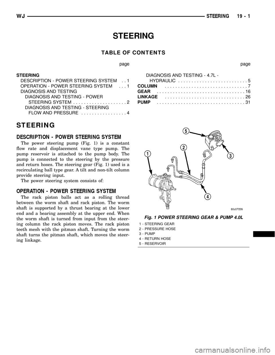
DESCRIPTION - POWER STEERING SYSTEM
The power steering pump (Fig. 1) is a constant
flow rate and displacement vane type pump. The
pump reservoir is attached to the pump body. The
pump is connected to the steering by the pressure
and return hoses. The steering gear (Fig. 1) used is a
recirculating ball type gear. A tilt and non-tilt column
provide steering input.
The power steering system consists of:
OPERATION - POWER STEERING SYSTEM
The rack piston balls act as a rolling thread
between the worm shaft and rack piston. The worm
shaft is supported by a thrust bearing at the lower
end and a bearing assembly at the upper end. When
the worm shaft is turned from input from the steer-
ing column the rack piston moves. The rack piston
teeth mesh with the pitman shaft. Turning the worm
shaft turns the pitman shaft, which moves the steer-
ing linkage.
Fig. 1 POWER STEERING GEAR & PUMP 4.0L
1 - STEERING GEAR
2 - PRESSURE HOSE
3 - PUMP
4 - RETURN HOSE
5 - RESERVOIR
WJSTEERING 19 - 1
Page 1484 of 2199

COLUMN
TABLE OF CONTENTS
page page
COLUMN
DESCRIPTION
SERVICE WARNINGS AND CAUTIONS......7
REMOVAL.............................8
INSTALLATION.........................11
SPECIFICATIONS
TORQUE CHART......................12
SPECIAL TOOLS
STEERING COLUMN...................12
IGNITION SWITCH
DESCRIPTION.........................12
DIAGNOSIS AND TESTING - IGNITION
SWITCH............................12
REMOVAL
IGNITION SWITCH REMOVAL............13INSTALLATION
IGNITION SWITCH INSTALLATION........13
KEY-IN IGNITION SWITCH
DESCRIPTION.........................14
OPERATION...........................14
DIAGNOSIS AND TESTING
KEY-IN IGNITION SWITCH..............14
LOCK CYLINDER
REMOVAL.............................14
INSTALLATION.........................15
STEERING WHEEL
REMOVAL.............................15
INSTALLATION.........................15
COLUMN
DESCRIPTION
SERVICE WARNINGS AND CAUTIONS
DESCRIPTION
The tilt column (Fig. 1) has been designed to be
serviced as an assembly, less the wiring, switches,
shrouds, steering wheel, etc. Most steering column
components can be serviced without removing the
steering column from the vehicle.To service the steering wheel, switches or air-
bag,(Refer to 8 - ELECTRICAL/RESTRAINTS -
WARNING).
WARNING: THE AIRBAG SYSTEM IS A SENSITIVE,
COMPLEX ELECTRO-MECHANICAL UNIT. BEFORE
ATTEMPTING TO DIAGNOSE, REMOVE OR INSTALL
THE AIRBAG SYSTEM COMPONENTS YOU MUST
FIRST DISCONNECT AND ISOLATE THE BATTERY
NEGATIVE (GROUND) CABLE. THEN WAIT TWO
MINUTES FOR THE SYSTEM CAPACITOR TO DIS-
CHARGE. FAILURE TO DO SO COULD RESULT IN
ACCIDENTAL DEPLOYMENT OF THE AIRBAG AND
POSSIBLE PERSONAL INJURY. THE FASTENERS,
SCREWS, AND BOLTS, ORIGINALLY USED FOR
THE AIRBAG COMPONENTS, HAVE SPECIAL COAT-
INGS AND ARE SPECIFICALLY DESIGNED FOR THE
AIRBAG SYSTEM. THEY MUST NEVER BE
REPLACED WITH ANY SUBSTITUTES. ANYTIME A
NEW FASTENER IS NEEDED, REPLACE WITH THE
CORRECT FASTENERS PROVIDED IN THE SERVICE
PACKAGE OR FASTENERS LISTED IN THE PARTS
BOOKS.
CAUTION: Safety goggles should be worn at all
times when working on steering columns.
Fig. 1 Steering Column
WJCOLUMN 19 - 7
Page 1491 of 2199

KEY-IN IGNITION SWITCH
DESCRIPTION
The key-in ignition switch is concealed within and
integral to the ignition switch, which is mounted on
the steering column. The key-in ignition switch is
actuated by the ignition lock cylinder mechanism,
and is hard wired between a body ground and the
Body Control Module (BCM) through the instrument
panel wire harness.
The key-in ignition switch cannot be adjusted or
repaired and, if faulty or damaged, the entire igni-
tion switch unit must be replaced,(Refer to 19 -
STEERING/COLUMN/LOCK CYLINDER HOUSING
- REMOVAL). For complete circuit diagrams, refer to
Body Control Modulein the Contents of Wiring
Diagrams.
OPERATION
The key-in ignition switch closes a path to ground
for the BCM when the ignition key is inserted in the
ignition lock cylinder, and opens the ground path
when the key is removed from the ignition lock cyl-
inder. The BCM monitors the key-in ignition switch
status through an internal pull-up, then sends the
proper switch status messages to other electronic
modules over the Programmable Communications
Interface (PCI) data bus network. The key-in ignition
switch status is also used by the BCM as an input
for chime warning system operation.
DIAGNOSIS AND TESTING
KEY-IN IGNITION SWITCH
For complete circuit diagrams, refer toBody Con-
trol Modulein the Contents of Wiring Diagrams.
WARNING: ON VEHICLES EQUIPPED WITH AIR-
BAGS, REFER TO GROUP 8M - PASSIVE
RESTRAINT SYSTEMS BEFORE ATTEMPTING ANY
STEERING WHEEL, STEERING COLUMN, OR
INSTRUMENT PANEL COMPONENT DIAGNOSIS OR
SERVICE. FAILURE TO TAKE THE PROPER PRE-
CAUTIONS COULD RESULT IN ACCIDENTAL AIR-
BAG DEPLOYMENT AND POSSIBLE PERSONAL
INJURY.(1) Disconnect and isolate the battery negative
cable. Disconnect the instrument panel wire harness
connector from the key-in ignition switch connector
receptacle on the ignition switch. Check for continu-
ity between the key-in ignition switch sense and
ground terminals of the key-in ignition switch con-
nector receptacle. There should be continuity with
the key inserted in the ignition lock cylinder, and no
continuity with the key removed from the ignition
lock cylinder. If OK, go to Step 2. If not OK, replace
the faulty ignition switch unit.
(2) Check for continuity between the ground cir-
cuit cavity of the instrument panel wire harness con-
nector for the key-in ignition switch and a good
ground. There should be continuity. If OK, go to Step
3. If not OK, repair the open ground circuit to ground
as required.
(3) Disconnect the gray 26-way instrument panel
wire harness connector from the Body Control Mod-
ule (BCM) connector receptacle. Check for continuity
between the key-in ignition switch sense circuit cav-
ity of the instrument panel wire harness connector
for the key-in ignition switch and a good ground.
There should be no continuity. If OK, go to Step 4. If
not OK, repair the shorted key-in ignition switch
sense circuit as required.
(4) Check for continuity between the key-in igni-
tion switch sense circuit cavities of the instrument
panel wire harness connector for the key-in ignition
switch and the gray 26-way instrument panel wire
harness connector for the BCM. There should be con-
tinuity. If OK, use a DRB scan tool and the proper
Diagnostic Procedures manual to test the BCM. If
not OK, repair the open key-in ignition switch sense
circuit as required.
LOCK CYLINDER
REMOVAL
The ignition key must be in the key cylinder for
cylinder removal. The key cylinder must be removed
first before removing ignition switch.
(1) Disconnect negative battery cable at battery.
(2) If equipped with an automatic transmission,
place shifter in PARK position.
(3) Rotate key to ON position.
19 - 14 COLUMNWJ
Page 1493 of 2199

GEAR
TABLE OF CONTENTS
page page
GEAR
DESCRIPTION.........................16
OPERATION...........................16
REMOVAL.............................16
INSTALLATION.........................16
ADJUSTMENTS
STEERING GEAR.....................18
SPECIFICATIONS
POWER STEERING GEAR..............18
SPECIAL TOOLS
POWER STEERING GEAR..............19
PITMAN SHAFT
REMOVAL.............................20INSTALLATION.........................20
PITMAN SHAFT BEARING
REMOVAL.............................22
INSTALLATION.........................22
PITMAN SHAFT SEAL
REMOVAL.............................22
INSTALLATION.........................23
RACK PISTON/VALVE ASSEMBLY
REMOVAL.............................23
INSTALLATION.........................25
STUB SHAFT HOUSING
REMOVAL.............................25
INSTALLATION.........................25
GEAR
DESCRIPTION
The power steering gear is a recirculating ball type
gear (Fig. 1) .
The following gear components can be serviced:
²Pitman Shaft and Cover
²Pitman Shaft Bearings
²Pitman Shaft Oil Seal/Dust Seal
²Stud Shaft Housing with Seal
²O-Rings and Teflon Rings
NOTE: If rack piston assembly is damaged the gear
must be replaced.
OPERATION
The gear acts as a rolling thread between the
worm shaft and rack piston. The worm shaft is sup-
ported by a thrust bearing at the lower end and a
bearing assembly at the upper end. When the worm
shaft is turned the rack piston moves. The rack pis-
ton teeth mesh with the pitman shaft. Turning the
worm shaft turns the pitman shaft, which turns the
steering linkage.
REMOVAL
(1) Place the front wheels in the straight ahead
position with the steering wheel centered and locked.
(2) Remove the air cleaner housing,(Refer to 9 -
ENGINE/AIR INTAKE SYSTEM/AIR CLEANER
HOUSING - REMOVAL).
(3) Drain or siphon the power steering system.(4) Remove the pressure and return lines (Fig.
2)from the steering gear. Refer to hose removal in
this section.
(5) Remove the column coupler shaft bolt (Fig.
2)and remove the shaft from the gear.
(6) Raise and support the vehicle.
(7) Remove the left front wheel and tire assembly.
(8) Remove the pitman arm from gear with Puller
C-4150A.
(9) Remove the windshield washer reservoir,(Refer
to 8 - ELECTRICAL/WIPERS/WASHERS/WASHER
RESERVOIR - REMOVAL).
(10) Remove the steering gear mounting bolts.
Remove the steering gear out of the engine compart-
ment (Fig. 3).
INSTALLATION
(1) Position the steering gear on the frame rail and
install the bolts. Tighten the bolts to 108 N´m (80 ft.
lbs.) torque.
(2) Install the pitman arm and tighten nut to 251
N´m (185 ft. lbs.).
(3) Install windshield washer reservoir,(Refer to 8 -
ELECTRICAL/WIPERS/WASHERS/WASHER RES-
ERVOIR - INSTALLATION).
(4) Install the wheel and tire assembly.
(5) Remove the support and lower the vehicle.
(6) Install the pressure and return hoses to the
steering gear and tighten to 20-38 N´m (14-28 ft.
lbs.).
(7) Install the column coupler shaft.
(8) Install the air cleaner housing,(Refer to 9 -
ENGINE/AIR INTAKE SYSTEM/AIR CLEANER
HOUSING - INSTALLATION).
19 - 16 GEARWJ
Page 1503 of 2199

LINKAGE
TABLE OF CONTENTS
page page
LINKAGE
DESCRIPTION
STEERING LINKAGE ± RIGHT HAND DRIVE
(RHD) VEHICLES......................26
DESCRIPTION........................26
SPECIFICATIONS
TORQUE CHART......................28
SPECIAL TOOLS
STEERING LINKAGE...................28
DAMPER
DESCRIPTION.........................28
OPERATION...........................28
REMOVAL.............................28
INSTALLATION.........................29
DRAG LINK
DESCRIPTION.........................29OPERATION...........................29
REMOVAL.............................29
INSTALLATION.........................29
PITMAN ARM
DESCRIPTION.........................29
OPERATION...........................29
REMOVAL.............................29
INSTALLATION.........................30
TIE ROD END
DESCRIPTION.........................30
OPERATION...........................30
REMOVAL.............................30
INSTALLATION.........................30
LINKAGE
DESCRIPTION
STEERING LINKAGE ± RIGHT HAND DRIVE
(RHD) VEHICLES
Vehicles equipped with right hand drive (RHD)
steering utilize the same components of left hand
drive vehicles. The RHD Steering linkage is designed
as a mirror image of left hand drive linkage with the
exception of the steering damper (Fig. 1), which is
mounted on the same side of the vehicle weather
RHD or LHD. See figure below for reference. All
specifications are the same as LHD. Refer to Group
19, Steering of the gasoline engine service manual for
additional information.
DESCRIPTION
The steering linkage consists of a pitman arm,
drag link, tie rod, and steering dampener (Fig. 2) .
An adjustment sleeve on the tie rod is used to set
wheel toe position. The sleeve on the drag link is
used for steering wheel centering.
CAUTION: If any steering components are replaced
or serviced an alignment must be performed, to
ensure the vehicle meets all alignment specifica-
tions.
CAUTION: Components attached with a nut and cot-
ter pin must be torqued to specification. Then if the
slot in the nut does not line up with the cotter pin
hole, tighten nut until it is aligned. Never loosen the
nut to align the cotter pin hole.
19 - 26 LINKAGEWJ