Park brake JEEP GRAND CHEROKEE 2003 WJ / 2.G Repair Manual
[x] Cancel search | Manufacturer: JEEP, Model Year: 2003, Model line: GRAND CHEROKEE, Model: JEEP GRAND CHEROKEE 2003 WJ / 2.GPages: 2199, PDF Size: 76.01 MB
Page 1170 of 2199
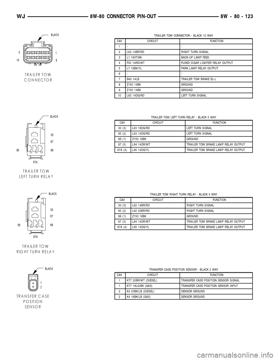
TRAILER TOW CONNECTOR - BLACK 10 WAY
CAV CIRCUIT FUNCTION
1- -
2 L62 14BR/RD RIGHT TURN SIGNAL
3 L1 18VT/BK BACK-UP LAMP FEED
4 F30 14RD/WT FUSED CIGAR LIGHTER RELAY OUTPUT
5 L7 18BK/YL PARK LAMP RELAY OUTPUT
6- -
7 B40 14LB TRAILER TOW BRAKE B(+)
8 Z150 14BK GROUND
9 Z150 14BK GROUND
10 L63 14DG/RD LEFT TURN SIGNAL
TRAILER TOW LEFT TURN RELAY - BLACK 5 WAY
CAV CIRCUIT FUNCTION
30 (3) L63 16DG/RD LEFT TURN SIGNAL
85 (2) L63 14DG/RD LEFT TURN SIGNAL
86 (1) Z150 18BK GROUND
87 (5) L94 14OR/WT TRAILER TOW BRAKE LAMP RELAY OUTPUT
87A (4) L95 14DG/YL TRAILER TOW BRAKE LAMP RELAY OUTPUT
TRAILER TOW RIGHT TURN RELAY - BLACK 5 WAY
CAV CIRCUIT FUNCTION
30 (3) L62 14BR/RD RIGHT TURN SIGNAL
85 (2) L62 20BR/RD RIGHT TURN SIGNAL
86 (1) Z150 18BK GROUND
87 (5) L94 14OR/WT TRAILER TOW BRAKE LAMP RELAY OUTPUT
87A (4) L95 14DG/YL TRAILER TOW BRAKE LAMP RELAY OUTPUT
TRANSFER CASE POSITION SENSOR - BLACK 2 WAY
CAV CIRCUIT FUNCTION
1 K77 20BR/WT (DIESEL) TRANSFER CASE POSITION SENSOR SIGNAL
1 K77 18LG/BK (GAS) TRANSFER CASE POSITION SENSOR INPUT
2 K4 20BK/LB (DIESEL) SENSOR GROUND
2 K4 18BK/LB (GAS) SENSOR GROUND
WJ8W-80 CONNECTOR PIN-OUT 8W - 80 - 123
Page 1176 of 2199
8W-91 CONNECTOR/GROUND/SPLICE LOCATION
TABLE OF CONTENTS
page
CONNECTOR/GROUND/SPLICE LOCATION
DESCRIPTION..........................1
CONNECTOR/GROUND/SPLICE
LOCATION
DESCRIPTION
This section provides illustrations identifying con-
nector, ground, and splice locations in the vehicle.Connector, ground, and splice indexes are provided.
Use the wiring diagrams in each section for connec-
tor, ground, and splice identification. Refer to the
appropriate index for the proper figure number. For
items that are not shown in this section N/S is placed
in the Fig. column.
CONNECTORS
CONNECTOR NAME/
NUMBERCOLOR LOCATION FIG.
A/C Compressor Clutch BK At A/C Compressor 9, 13
A/C Pressure Transducer BK Right Front of Engine Compartment 3, 4, 5
Accelerator Pedal Position
Sensor (Diesel)BK Rear of Engine Compartment Near
Fuel/Water Seperator7
Adjustable Pedals Module
(Except Built-up Export)GN Above Drivers Control Pedals N/S
Adjustable Pedals Motor/
Sensor Assembly (Except
Built-up Export)Above Drivers Control Pedals N/S
Adjustable Pedals Switch WT Drivers Lower Kick Panel 21
Airbag Control Module (ORC)
C1YL Below Center Floor Console, Near
Park Brake19, 20, 21, 22
Airbag Control Module (ORC)
C2YL Below Center Floor Console, Near
Park Brake19, 20, 21, 22
Ambient Temperature Sensor BK On Radiator Center Support 5
Antenna Module (Built-up-
export)WT Above Right Quarter Window N/S
Ash Receiver Lamp BK Below Cigarette Lighter 19, 20
Automatic Day/Night Mirror BK In Front of Rear View Mirror N/S
Automatic Headlamp Light
Sensor/VTSS LEDBK Near Left Instrument Panel Speaker 19, 20
Automatic Zone Control
Module - C1 (AZC)WT Left Side of HVAC Housing N/S
Automatic Zone Control
Module - C2 (AZC)WT Left Side of HVAC Housing N/S
Battery Temperature Sensor BK Below Battery Tray 4, 5
Blower Motor BK Behind Right Hand Side of
Instrument PanelN/S
WJ8W-91 CONNECTOR/GROUND/SPLICE LOCATION 8W - 91 - 1
Page 1177 of 2199
CONNECTOR NAME/
NUMBERCOLOR LOCATION FIG.
Blower Motor Controller (AZC) BK Behind Right Hand Side of
Instrument PanelN/S
Blower Motor Resistor Block
(MTC)BK Behind Right Hand Side of
Instrument PanelN/S
Body Control Module - C1 GY Lower Left Side of Instrument Panel 21, 22
Body Control Module-C2 -LHD WT Lower Left Side of Instrument Panel 21
Body Control Module-C2 -
RHDGY Lower Left Side of Instrument Panel 22
Boost Pressure Sensor
(Diesel)BK Top Front of Engine N/S
Brake Lamp Switch GY Brake Pedal Arm 31
C100 BK Right Front Engine Compartment 2, 5
C101 (4.0L RHD) LTGY Rear of Engine Compartment 15
C101 (4.7L RHD) BK Rear of Engine Compartment N/S
C102 (Diesel) BK Left Rear Engine Compartment 4, 7
C102 (Gas) BK Right Rear Engine Compartment 5, 10, 11, 14, 15, 18
C103 (Diesel) LTGY Rear of Engine 4, 7
C103 (Gas) GY Right Rear Engine Compartment 5, 10 11, 14, 15
C104 LTGY Right Rear Engine Compartment 14 18
C105 (Diesel) GY Right Rear Engine Compartment 4, 7, 8
C106 (Diesel) GY Lower Right Instrument Panel N/S
C106 (Gas RHD) GY Lower Right Instrument Panel N/S
C107 (Diesel) GY Left Rear Engine Compartment 4
C107 (LHD) BK Passenger Side Near Kick Panel 3, 30, 35
C107 (RHD) GY Passenger Side Near Kick Panel 3, 31
C108 BK Left Cowl 3, 4
C109 BK Near Transfer Case switch 12
C110 (Diesel) GY Top of Engine Near Glow Plugs 4, 7
C111 BK Left Front Frame Near Windshield
Washer Pump1, 3, 4
C112 BK Right Front Frame Near Horns 1, 5
C113 (Diesel) LTGY Rear of Engine 7, 8
C200 - LHD GY Passenger Side Near Kick Panel 19, 21, 35
C200 - RHD BK Passenger Side Near Kick Panel 20, 22
C201) WT Below Center Floor Console, Near
Park Brake19, 20, 21, 22
C202 WT HVAC Unit, Right Side of Instrument
Panel19, 20, 21, 22
C203 (AZC) WT HVAC Unit, Right Side of Instrument
Panel19, 20, 21, 22
C300 (LHD) GY Near Junction Block 30, 33
C301 (RHD) BK Near Junction Block 31
C302 BK At Driver Door 24, 25, 30, 31
8W - 91 - 2 8W-91 CONNECTOR/GROUND/SPLICE LOCATIONWJ
CONNECTOR/GROUND/SPLICE LOCATION (Continued)
Page 1183 of 2199
CONNECTOR NAME/
NUMBERCOLOR LOCATION FIG.
Output Speed Sensor (4.0L) GY Left Side of Transmission 12
Output Speed Sensor (4.7L) BK Left Side of Transmission 16
Overhead Map/Courtesy Lamp WT At Overhead Console N/S
Oxygen Sensor 1/1 Upstream
(4.0L)GY Left Side of Engine at Exhaust 9, 12
Oxygen Sensor 1/1 Upstream
(4.7L)GY Left Side of Engine at Exhaust 17
Oxygen Sensor 1/2
Downstream (4.0L)BK Rear of Transmission 9, 12
Oxygen Sensor 1/2
Downstream (4.7L)BK Rear of Transmission 17
Oxygen Sensor 2/1 Upstream Rear of Transmission N/S
Oxygen Sensor 2/2
DownstreamRear of Transmission N/S
Park Brake Switch Center Console Area, Near Airbag
Control Module20, 21, 22
Park/Neutral Position Switch
(4.0L)BK Left Side of Transmission 12
Park/Neutral Position Switch
(Diesel)BK Left Side of Transmission N/S
Passenger Airbag YL Passenger Side of Instrument Panel 19, 20
Passenger Blend Door
Motor/Actuator (AZC)BK Passenger Side of Instrument Panel N/S
Passenger Door Lock
Motor/Ajar SwitchBK In Passenger Door 26, 27
Passenger Door Module - C1 WT In Passenger Door 26, 27
Passenger Door Module - C2 BK In Passenger Door N/S
Passenger Front Door
Courtesy LampBK In Passenger Door N/S
Passenger Front Power
Window MotorBK In Passenger Door 26, 27
Passenger Heated Seat Back
(Premium I/III)GN At Passenger Seat N/S
Passenger Heated Seat
Cushion (Premium I/III)BK At Passenger Seat N/S
Passenger Heated Seat Switch BK Center of Instrument Panel 19, 20, 21
Passenger Lumbar Motor
(Midline/Premium)BK At Passenger Seat N/S
Passenger Lumbar Switch
(Midline/Premium)WT At Passenger Seat N/S
Passenger Power Mirror BK In Passenger Door N/S
Passenger Power Seat Front
Riser MotorRD At Passenger Seat N/S
Passenger Power Seat
Horizontal MotorRD At Passenger Seat N/S
8W - 91 - 8 8W-91 CONNECTOR/GROUND/SPLICE LOCATIONWJ
CONNECTOR/GROUND/SPLICE LOCATION (Continued)
Page 1184 of 2199
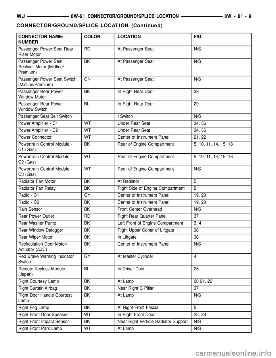
CONNECTOR NAME/
NUMBERCOLOR LOCATION FIG.
Passenger Power Seat Rear
Riser MotorRD At Passenger Seat N/S
Passenger Power Seat
Recliner Motor (Midline/
Premium)BK At Passenger Seat N/S
Passenger Power Seat Switch
(Midline/Premium)GN At Passenger Seat N/S
Passenger Rear Power
Window MotorBK In Right Rear Door 29
Passenger Rear Power
Window SwitchBL In Right Rear Door 29
Passenger Seat Belt Switch t Switch N/S
Power Amplifier - C1 WT Under Rear Seat 34, 36
Power Amplifier - C2 WT Under Rear Seat 34, 36
Power Connector WT Center of Instrument Panel 21, 22
Powertrain Control Module -
C1 (Gas)BK Rear of Engine Compartment 5, 10, 11, 14, 15, 18
Powertrain Control Module -
C2 (Gas)WT Rear of Engine Compartment 5, 10, 11, 14, 15, 18
Powertrain Control Module -
C3 (Gas)WT Rear of Engine Compartment N/S
Radiator Fan Motor BK At Radiator 5
Radiator Fan Relay BK Right Side of Engine Compartment 5
Radio - C1 GY Center of Instrument Panel 19, 20
Radio - C2 BK Center of Instrument Panel 19, 20
Rain Sensor BK Front Center Overhead N/S
Rear Power Outlet RD Right Rear Quarter Panel 37
Rear Washer Pump BK Left Front of Engine Compartment 3, 4
Rear Window Defogger BK Right Upper Coner of Liftgate 38
Rear Wiper Motor BK In Liftgate 38
Recirculation Door Motor/
Actuator (AZC)BK Center of Instrument Panel N/S
Red Brake Warning Indicator
SwitchGY At Master Cylinder 4
Remote Keyless Module
(Japan)BL In Driver Door 25
Right Courtesy Lamp BK At Lamp 20 21, 22
Right Curtain Airbag BK Near Right C Pillar 37
Right Door Handle Courtesy
LampBK At Lamp N/S
Right Fog Lamp BK At Right Front Fascia 5
Right Front Door Speaker WT In Right Front Door 25, 26
Right Front Impact Sensor BK Near Right Verticle Radiator Support N/S
Right Front Park Lamp WT At Lamp N/S
WJ8W-91 CONNECTOR/GROUND/SPLICE LOCATION 8W - 91 - 9
CONNECTOR/GROUND/SPLICE LOCATION (Continued)
Page 1489 of 2199
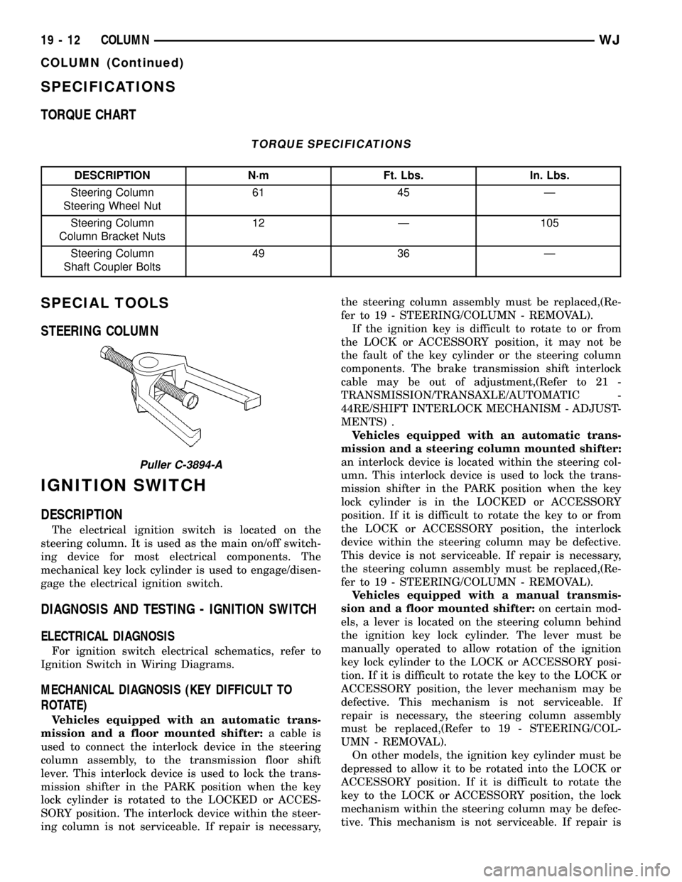
SPECIFICATIONS
TORQUE CHART
TORQUE SPECIFICATIONS
DESCRIPTION N´m Ft. Lbs. In. Lbs.
Steering Column
Steering Wheel Nut61 45 Ð
Steering Column
Column Bracket Nuts12 Ð 105
Steering Column
Shaft Coupler Bolts49 36 Ð
SPECIAL TOOLS
STEERING COLUMN
IGNITION SWITCH
DESCRIPTION
The electrical ignition switch is located on the
steering column. It is used as the main on/off switch-
ing device for most electrical components. The
mechanical key lock cylinder is used to engage/disen-
gage the electrical ignition switch.
DIAGNOSIS AND TESTING - IGNITION SWITCH
ELECTRICAL DIAGNOSIS
For ignition switch electrical schematics, refer to
Ignition Switch in Wiring Diagrams.
MECHANICAL DIAGNOSIS (KEY DIFFICULT TO
ROTATE)
Vehicles equipped with an automatic trans-
mission and a floor mounted shifter:a cable is
used to connect the interlock device in the steering
column assembly, to the transmission floor shift
lever. This interlock device is used to lock the trans-
mission shifter in the PARK position when the key
lock cylinder is rotated to the LOCKED or ACCES-
SORY position. The interlock device within the steer-
ing column is not serviceable. If repair is necessary,the steering column assembly must be replaced,(Re-
fer to 19 - STEERING/COLUMN - REMOVAL).
If the ignition key is difficult to rotate to or from
the LOCK or ACCESSORY position, it may not be
the fault of the key cylinder or the steering column
components. The brake transmission shift interlock
cable may be out of adjustment,(Refer to 21 -
TRANSMISSION/TRANSAXLE/AUTOMATIC -
44RE/SHIFT INTERLOCK MECHANISM - ADJUST-
MENTS) .
Vehicles equipped with an automatic trans-
mission and a steering column mounted shifter:
an interlock device is located within the steering col-
umn. This interlock device is used to lock the trans-
mission shifter in the PARK position when the key
lock cylinder is in the LOCKED or ACCESSORY
position. If it is difficult to rotate the key to or from
the LOCK or ACCESSORY position, the interlock
device within the steering column may be defective.
This device is not serviceable. If repair is necessary,
the steering column assembly must be replaced,(Re-
fer to 19 - STEERING/COLUMN - REMOVAL).
Vehicles equipped with a manual transmis-
sion and a floor mounted shifter:on certain mod-
els, a lever is located on the steering column behind
the ignition key lock cylinder. The lever must be
manually operated to allow rotation of the ignition
key lock cylinder to the LOCK or ACCESSORY posi-
tion. If it is difficult to rotate the key to the LOCK or
ACCESSORY position, the lever mechanism may be
defective. This mechanism is not serviceable. If
repair is necessary, the steering column assembly
must be replaced,(Refer to 19 - STEERING/COL-
UMN - REMOVAL).
On other models, the ignition key cylinder must be
depressed to allow it to be rotated into the LOCK or
ACCESSORY position. If it is difficult to rotate the
key to the LOCK or ACCESSORY position, the lock
mechanism within the steering column may be defec-
tive. This mechanism is not serviceable. If repair is
Puller C-3894-A
19 - 12 COLUMNWJ
COLUMN (Continued)
Page 1582 of 2199

BRAKE TRANSMISSION SHIFT
INTERLOCK MECHANISM
DESCRIPTION
The Brake Transmission Shifter/Ignition Interlock
(BTSI), is a cable and solenoid operated system. It
interconnects the automatic transmission floor
mounted shifter to the steering column ignition
switch (Fig. 71).
OPERATION
The system locks the shifter into the PARK posi-
tion. The interlock system is engaged whenever the
ignition switch is in the LOCK or ACCESSORY posi-
tion. An additional electrically activated feature will
prevent shifting out of the PARK position unless the
brake pedal is depressed approximately one-half an
inch. A magnetic holding device in the shifter assem-
bly is energized when the ignition is in the RUN
position. When the key is in the RUN position and
the brake pedal is depressed, the shifter is unlocked
and will move into any position. The interlock system
also prevents the ignition switch from being turned
to the LOCK or ACCESSORY position, unless the
shifter is fully locked into the PARK position.
DIAGNOSIS AND TESTING - BRAKE
TRANSMISSION SHIFT INTERLOCK
(1) Verify that the key can only be removed in the
PARK position
(2) When the shift lever is in PARK And the shift
handle pushbutton is in the ªOUTº position, the igni-
tion key cylinder should rotate freely from OFF to
LOCK. When the shifter is in any other gear or neu-
tral position, the ignition key cylinder should not
rotate to the LOCK position.
(3) Shifting out of PARK should not be possible
when the ignition key cylinder is in the OFF posi-
tion.
(4) Shifting out of PARK should not be possible
while applying normal pushbutton force and ignition
key cylinder is in the RUN or START positions
unless the foot brake pedal is depressed approxi-
mately 1/2 inch (12mm).
(5) Shifting out of PARK should not be possible
when the ignition key cylinder is in the ACCESSORY
or LOCK positions.
(6) Shifting between any gears, NEUTRAL or into
PARK may be done without depressing foot brake
pedal with ignition switch in RUN or START posi-
tions.
Fig. 71 Ignition Interlock Cable
1 - SHIFT MECHANISM 4 - STEERING COLUMN ASSEMBLY
2 - SHIFTER BTSI LEVER 5 - INTERLOCK CABLE
3 - ADJUSTMENT CLIP
WJAUTOMATIC TRANSMISSION - 42RE 21 - 63
Page 1583 of 2199

ADJUSTMENTS - BRAKE TRANSMISSION
SHIFT INTERLOCK
The park interlock cable is part of the brake/shift
lever interlock system. Correct cable adjustment is
important to proper interlock operation. The gear
shift and park lock cables must both be correctly
adjusted in order to shift out of PARK.
ADJUSTMENT PROCEDURE
(1) Remove floor console as necessary for access to
the brake transmission shift interlock cable. (Refer to
23 - BODY/INTERIOR/FLOOR CONSOLE -
REMOVAL)
(2) Shift the transmission into the PARK position.
(3) Turn ignition switch to LOCK position.Be
sure ignition key cylinder is in the LOCK posi-
tion. Cable will not adjust correctly in any
other position.
(4) Pull cable lock button up to release cable (Fig.
72).
(5) Ensure that the cable is free to self-adjust by
pushing cable rearward and releasing.
(6) Push lock button down until it snaps in place.
BTSI FUNCTION CHECK
(1) Verify removal of ignition key allowed in PARK
position only.
(2) When the shift lever is in PARK, and the shift
handle push-button is in the out position, the igni-
tion key cylinder should rotate freely from off to lock.
When the shifter is in any other position, the ignition
key should not rotate from off to lock.
(3) Shifting out of PARK should be possible when
the ignition key cylinder is in the off position.
(4) Shifting out of PARK should not be possible
while applying normal push-button force, and igni-
tion key cylinder is in the run or start positions,
unless the foot brake pedal is depressed approxi-
mately 1/2 inch (12mm).
(5) Shifting out of PARK should not be possible
when the ignition key cylinder is in the accessory or
lock position.
(6) Shifting between any gear and NEUTRAL, or
PARK, may be done without depressing foot brake
with ignition switch in run or start positions.
(7) The floor shifter lever and gate positions
should be in alignment with all transmission detent
positions.
Fig. 72 Brake Transmission Shift Interlock Cable
1 - SHIFT MECHANISM 4 - STEERING COLUMN ASSEMBLY
2 - SHIFTER BTSI LEVER 5 - INTERLOCK CABLE
3 - ADJUSTMENT CLIP
21 - 64 AUTOMATIC TRANSMISSION - 42REWJ
BRAKE TRANSMISSION SHIFT INTERLOCK MECHANISM (Continued)
Page 1584 of 2199

(8) Engine starts must be possible with shifter
lever in PARK or NEUTRAL gate positions only.
Engine starts must not be possible in any other gate
positions other than PARK or NEUTRAL.
(9) With shifter lever handle push-button not
depressed and lever detent in:
²PARK position- apply forward force on center of
handle and remove pressure. Engine start must be
possible.
²PARK position- apply rearward force on center
of handle and remove pressure. Engine start must be
possible.
²NEUTRAL position- engine start must be possi-
ble.
²NEUTRAL position, engine running and brakes
applied- Apply forward force on center of shift han-
dle. Transmission should not be able to shift into
REVERSE detent.
ELECTRONIC GOVERNOR
DESCRIPTION
Governor pressure is controlled electronically. Com-
ponents used for governor pressure control include:
²Governor body
²Valve body transfer plate
²Governor pressure solenoid valve
²Governor pressure sensor
²Fluid temperature thermistor
²Throttle position sensor (TPS)
²Transmission speed sensor
²Powertrain control module (PCM)
GOVERNOR PRESSURE SOLENOID VALVE
The solenoid valve is a duty-cycle solenoid which
regulates the governor pressure needed for upshifts
and downshifts. It is an electro-hydraulic device
located in the governor body on the valve body trans-
fer plate (Fig. 73).
GOVERNOR PRESSURE SENSOR
The governor pressure sensor measures output
pressure of the governor pressure solenoid valve (Fig.
74).
GOVERNOR BODY AND TRANSFER PLATE
The transfer plate is designed to supply transmis-
sion line pressure to the governor pressure solenoid
valve and to return governor pressure.
The governor pressure solenoid valve is mounted in
the governor body. The body is bolted to the lower
side of the transfer plate (Fig. 74).
GOVERNOR PRESSURE CURVES
There are four governor pressure curves pro-
grammed into the transmission control module. The
different curves allow the control module to adjust
governor pressure for varying conditions. One curve
is used for operation when fluid temperature is at, or
below, ±1ÉC (30ÉF). A second curve is used when fluid
temperature is at, or above, 10ÉC (50ÉF) during nor-
mal city or highway driving. A third curve is used
during wide-open throttle operation. The fourth curve
is used when driving with the transfer case in low
range.
OPERATION
Compensation is required for performance varia-
tions of two of the input devices. Though the slope of
the transfer functions is tightly controlled, offset may
vary due to various environmental factors or manu-
facturing tolerances.
The pressure transducer is affected by barometric
pressure as well as temperature. Calibration of the
zero pressure offset is required to compensate for
shifting output due to these factors.
Fig. 73 Governor Pressure Solenoid Valve
1 - SOLENOID FILTER
2 - GOVERNOR PRESSURE SOLENOID
Fig. 74 Governor Pressure Sensor
1 - GOVERNOR BODY
2 - GOVERNOR PRESSURE SENSOR/TRANSMISSION FLUID
TEMPERATURE THERMISTOR
WJAUTOMATIC TRANSMISSION - 42RE 21 - 65
BRAKE TRANSMISSION SHIFT INTERLOCK MECHANISM (Continued)
Page 1589 of 2199

(1) A result of restricted fluid flow through the
main and/or auxiliary cooler. This condition is usu-
ally the result of a faulty or improperly installed
drainback valve, a damaged main cooler, or severe
restrictions in the coolers and lines caused by debris
or kinked lines.
(2) Heavy duty operation with a vehicle not prop-
erly equipped for this type of operation. Trailer tow-
ing or similar high load operation will overheat the
transmission fluid if the vehicle is improperly
equipped. Such vehicles should have an auxiliary
transmission fluid cooler, a heavy duty cooling sys-
tem, and the engine/axle ratio combination needed to
handle heavy loads.
DIAGNOSIS AND TESTING - FLUID
CONTAMINATION
Transmission fluid contamination is generally a
result of:
²adding incorrect fluid
²failure to clean dipstick and fill tube when
checking level
²engine coolant entering the fluid
²internal failure that generates debris
²overheat that generates sludge (fluid break-
down)
²failure to reverse flush cooler and lines after
repair
²failure to replace contaminated converter after
repair
The use of non-recommended fluids can result in
transmission failure. The usual results are erratic
shifts, slippage, abnormal wear and eventual failure
due to fluid breakdown and sludge formation. Avoid
this condition by using recommended fluids only.
The dipstick cap and fill tube should be wiped
clean before checking fluid level. Dirt, grease and
other foreign material on the cap and tube could fall
into the tube if not removed beforehand. Take the
time to wipe the cap and tube clean before withdraw-
ing the dipstick.
Engine coolant in the transmission fluid is gener-
ally caused by a cooler malfunction. The only remedy
is to replace the radiator as the cooler in the radiator
is not a serviceable part. If coolant has circulated
through the transmission, an overhaul is necessary.
The transmission cooler and lines should be
reverse flushed whenever a malfunction generates
sludge and/or debris. The torque converter should
also be replaced at the same time.
Failure to flush the cooler and lines will result in
recontamination. Flushing applies to auxiliary coolers
as well. The torque converter should also be replaced
whenever a failure generates sludge and debris. This
is necessary because normal converter flushing proce-
dures will not remove all contaminants.
STANDARD PROCEDURE
STANDARD PROCEDURE - FLUID LEVEL
CHECK
Low fluid level can cause a variety of conditions
because it allows the pump to take in air along with
the fluid. As in any hydraulic system, air bubbles
make the fluid spongy, therefore, pressures will be
low and build up slowly.
Improper filling can also raise the fluid level too
high. When the transmssion has too much fluid, the
geartrain churns up foam and cause the same condi-
tions which occur with a low fluid level.
In either case, air bubbles can cause overheating
and/or fluid oxidation, and varnishing. This can
interfere with normal valve, clutch, and accumulator
operation. Foaming can also result in fluid escaping
from the transmission vent where it may be mis-
taken for a leak.
After the fluid has been checked, seat the dipstick
fully to seal out water and dirt.
The transmission has a dipstick to check oil level.
It is located on the right side of the engine. Be sure
to wipe all dirt from dipstick handle before removing.
Fluid level is checked with the engine running at
curb idle speed, the transmission in NEUTRAL and
the transmission fluid at normal operating tempera-
ture.The engine should be running at idle
speed for at least one minute, with the vehicle
on level ground.
The transmission fluid level can be checked two
ways.
PROCEDURE ONE
(1) Transmission fluid must be at normal operat-
ing temperature for accurate fluid level check. Drive
vehicle if necessary to bring fluid temperature up to
normal hot operating temperature of 82ÉC (180ÉF).
(2) Position vehicle on level surface.
(3) Start and run engine at curb idle speed.
(4) Apply parking brakes.
(5) Shift transmission momentarily into all gear
ranges. Then shift transmission back to NEUTRAL.
(6) Clean top of filler tube and dipstick to keep
dirt from entering tube.
(7) Remove dipstick (Fig. 87) and check fluid level
as follows:
(a) Correct acceptable level is in crosshatch area.
(b) Correct maximum level is to MAX arrow
mark.
(c) Incorrect level is at or below MIN line.
(d) If fluid is low, add only enough MopartAT F
+4, type 9602, to restore correct level. Do not over-
fill.
21 - 70 AUTOMATIC TRANSMISSION - 42REWJ
FLUID AND FILTER (Continued)