Steering sensor JEEP GRAND CHEROKEE 2003 WJ / 2.G Repair Manual
[x] Cancel search | Manufacturer: JEEP, Model Year: 2003, Model line: GRAND CHEROKEE, Model: JEEP GRAND CHEROKEE 2003 WJ / 2.GPages: 2199, PDF Size: 76.01 MB
Page 627 of 2199

(1) Position the Rain Sensor Module (RSM) above
the inside rear view mirror (Fig. 15).
(2) Reconnect the overhead wire harness connector
for the RSM to the module connector receptacle.
(3) Position the RSM to the bracket on the wind-
shield above the inside rear view mirror.
(4) Using hand pressure, press the spring clips on
each side of the RSM until they snap over the
bracket on the windshield.
NOTE: The spring clips on the RSM will become
deformed after numerous (about ten) removal and
installation cycles. If the spring clips become
deformed, the RSM must be replaced with a new
unit.
(5) Align and engage the top of the trim cover over
the top of the RSM.
(6) Using hand pressure, press the bottom of the
trim cover toward the windshield glass until it snaps
over the bottom of the RSM.
(7) Reconnect the battery negative cable.
RIGHT MULTI-FUNCTION
SWITCH
DESCRIPTION
The right (wiper) multi-function switch is secured
to the right side of the multi-function switch mount-
ing housing at the top of the steering column, just
below the steering wheel (Fig. 16). The only visible
component of the right multi-function switch is the
control stalk that extends through a dedicated open-
ing in the right side of the steering column shrouds.
The remainder of the right multi-function switch is
concealed beneath the steering column shrouds. The
switch housing and its control stalk are constructed
of molded black plastic. A single connector receptacle
containing up to ten terminal pins is located on the
back of the switch housing and connects the switch
to the vehicle electrical system through a take out
and connector of the instrument panel wire harness.
The switch is secured to the multi-function switch
mounting housing near the top of the steering col-
umn by two screws.
There are two versions of the right multi-function
switch: one to support the standard equipment speed
sensitive intermittent front wiper system, and a sec-
ond to support the optional front automatic wiper
system. Each version of the right multi-function
switch control stalk has both white nomenclature
and International Control and Display Symbol icons
applied to it, which clearly identify its many func-
tions. The control stalk has a control knob on its end
with a flattened face to allow it to be easily rotated.
Just below the control knob is a knurled control
sleeve. The right multi-function switch is the primary
control for the front and rear wiper and washer sys-
tems, and contains switches and circuitry to provide
signals to the Body Control Module (BCM) and the
rear wiper module.
The right (wiper) multi-function switch cannot be
adjusted or repaired. If any function of the switch is
faulty, or if the switch is damaged, the entire switch
unit must be replaced.
The right (wiper) multi-function switch supports
the following functions and features:
²Automatic Front Wipe Mode- On models
equipped with the optional automatic wiper system,
the internal circuitry and hardware of the right
(wiper) multi-function switch control knob provide an
automatic front wipe mode with five sensitivity posi-
tions.
²Continuous Front Wipe Modes- The internal
circuitry and hardware of the right (wiper) multi-
function switch control knob provide two continuous
front wipe switch positions, low speed or high speed.
Fig. 16 Right (Wiper) Multi-Function Switch
1 - CONTROL STALK
2 - REAR WIPER CONTROL SLEEVE
3 - FRONT WIPER CONTROL KNOB
4 - RIGHT (WIPER) MULTI-FUNCTION SWITCH
8R - 20 FRONT WIPERS/WASHERSWJ
RAIN SENSOR MODULE (Continued)
Page 628 of 2199

²Continuous Rear Wipe Mode- The internal
circuitry and hardware of the right (wiper) multi-
function switch control sleeve provides one continu-
ous rear wipe switch position.
²Front Washer Mode- The internal circuitry
and hardware of the right (wiper) multi-function
switch control stalk provide front washer system
operation.
²Front Wipe-After-Wash Mode- The internal
circuitry and hardware of the right (wiper) multi-
function switch control stalk provide a wipe-after-
wash mode.
²Front Wiper Mist Mode- The internal cir-
cuitry and hardware of the right (wiper) multi-func-
tion switch control stalk provide a front wiper system
mist mode.
²Intermittent Front Wipe Mode- The internal
circuitry and hardware of the right (wiper) multi-
function switch control knob provide an intermittent
front wipe mode with five delay interval positions,
except on models equipped with the optional auto-
matic wiper system.
²Intermittent Rear Wipe Mode- The internal
circuitry and hardware of the right (wiper) multi-
function switch control ring provide one fixed inter-
val intermittent rear wipe mode switch position.
²Rear Washer Mode- The internal circuitry and
hardware of the right (wiper) multi-function switch
control stalk provide rear washer system operation.
OPERATION
The right (wiper) multi-function switch uses a com-
bination of resistor multiplexed and conventionally
switched outputs to control the many functions and
features it provides. The switch receives battery cur-
rent on a fused ignition switch output (run-acc) cir-
cuit from a fuse in the Junction Block (JB) whenever
the ignition switch is in the On or Accessory posi-
tions, and receives ground from the Body Control
Module (BCM) on a windshield wiper switch return
circuit. The right (wiper) multi-function switch may
be diagnosed using conventional diagnostic tools and
methods.
Following are descriptions of how the right (wiper)
multi-function switch control stalk operates to control
the functions and features it provides:
²Automatic Wipe Mode- On models equipped
with the optional automatic wiper system, the control
knob on the end of the right (wiper) multi-function
switch control stalk is rotated to one of five minor
intermediate detents to select the desired automatic
wipe sensitivity level. The control knob is rotated
rearward (counterclockwise) to reduce the sensitivity
(increase the interval between wipes), or forward
(clockwise) to increase the sensitivity (decrease the
interval between wipes). The right (wiper) multi-function switch provides a resistor multiplexed out-
put to the Body Control Module (BCM) on a
windshield wiper switch mux circuit. The BCM
responds by sending an electronic message to the
Rain Sensor Module (RSM) over the Programmable
Communications Interface (PCI) data bus indicating
the selected sensitivity level, and by operating the
front wiper system based upon electronic wipe com-
mands received from the RSM over the PCI data bus.
²Continuous Front Wipe Modes- The control
knob on the end of the right (wiper) multi-function
switch control stalk is rotated to an intermediate
detent that is one detent rearward (counterclockwise)
from the full forward (clockwise) detent to select the
low speed continuous front wiper mode, or to its full
forward (clockwise) detent to select the high speed
continuous front wiper mode. For the low speed
mode, the multi-function switch provides a resistor
multiplexed output to the Body Control Module
(BCM) on a windshield wiper switch mux circuit, and
the BCM responds by energizing the wiper on/off
relay in the Power Distribution Center (PDC) for the
front low speed continuous wipe mode. For the high
speed mode, the multi-function switch provides the
same resistor multiplexed output to the BCM on the
windshield wiper switch mux circuit as the low speed
mode, but also provides a ground output to the BCM
on a wiper high control circuit. The BCM responds to
these inputs by energizing the wiper on/off relay and
the wiper high/low relay in the PDC for the front
high speed continuous wipe mode.
²Continuous Rear Wipe Mode- The control
ring on the right (wiper) multi-function switch con-
trol stalk is rotated to the most forward (clockwise)
detent to select the continuous rear wiper mode. The
multi-function switch provides a battery current out-
put to the rear wiper motor on a rear wiper motor
control circuit to signal the rear wiper module to
operate the rear wiper motor in the continuous wipe
mode.
²Front Washer Mode- The control stalk of the
right (wiper) multi-function switch is pulled toward
the steering wheel to momentarily activate the front
washer pump/motor in the front washer mode. The
front washer pump will continue to operate in the
front washer mode until the control stalk is released.
The right (wiper) multi-function switch provides a
battery current output on a washer pump motor
switch output circuit to energize the front washer
pump in the front washer mode.
²Front Wiper Mist Mode- The control stalk of
the right (wiper) multi-function switch is pushed
towards the floor to momentarily activate the front
wiper motor in the mist mode. The front wiper motor
will continue to operate in the mist mode until the
control stalk is released. The right (wiper) multi-
WJFRONT WIPERS/WASHERS 8R - 21
RIGHT MULTI-FUNCTION SWITCH (Continued)
Page 629 of 2199

function switch provides a resistor multiplexed out-
put to the Body Control Module (BCM) on a
windshield wiper switch mux circuit, and the BCM
responds by energizing the wiper on/off relay in the
Power Distribution Center (PDC) to operate the front
wiper motor momentarily at low speed to provide the
front wiper mist mode.
²Intermittent Front Wipe Mode- On models
not equipped with the optional automatic wiper sys-
tem, the control knob on the end of the right (wiper)
multi-function switch control stalk is rotated to one
of five minor intermediate detents to select the
desired intermittent front wipe delay interval. The
control knob is rotated rearward (counterclockwise)
to increase the delay, or forward (clockwise) to
decrease the delay. The right (wiper) multi-function
switch provides a resistor multiplexed output to the
Body Control Module (BCM) on a windshield wiper
switch mux circuit. The BCM responds by monitoring
electronic vehicle speed messages received from the
Powertrain Control Module (PCM) over the Program-
mable Communications Interface (PCI) data bus,
then energizing the wiper on/off relay in the Power
Distribution Center (PDC) to operate the front wiper
motor at the proper delay intervals.
²Intermittent Rear Wipe Mode- The control
ring on the right (wiper) multi-function switch con-
trol stalk is rotated to the center detent to select the
intermittent rear wiper mode. The right (wiper)
multi-function switch provides a battery current out-
put to the rear wiper motor on a rear wiper motor
delay control circuit to signal the rear wiper module
to operate the rear wiper in the intermittent wipe
mode.
²Rear Washer Mode- The right (wiper) multi-
function switch control stalk is pushed forward
toward the instrument panel to a momentary posi-
tions to activate the rear washer pump/motor in the
rear washer mode. The rear washer pump will con-
tinue to operate in the rear washer mode until the
control stalk is released. The right (wiper) multi-
function switch provides battery current on a rear
washer pump motor control circuit to energize the
rear washer pump in the rear washer mode.DIAGNOSIS AND TESTING - RIGHT MULTI-
FUNCTION SWITCH
Be certain to perform the diagnosis for the front
wiper system, front washer system, rear wiper sys-
tem, and/or rear washer system before testing the
right multi-function switch. (Refer to 8 - ELECTRI-
CAL/FRONT WIPERS/WASHERS - DIAGNOSIS
AND TESTING) or (Refer to 8 - ELECTRICAL/REAR
WIPERS/WASHERS - DIAGNOSIS AND TESTING).
Refer to the appropriate wiring information. The wir-
ing information includes wiring diagrams, proper
wire and connector repair procedures, details of wire
harness routing and retention, connector pin-out
information and location views for the various wire
harness connectors, splices and grounds.
WARNING: ON VEHICLES EQUIPPED WITH AIR-
BAGS, DISABLE THE PASSIVE RESTRAINT SYS-
TEM BEFORE ATTEMPTING ANY STEERING
WHEEL, STEERING COLUMN, DRIVER AIRBAG,
PASSENGER AIRBAG. SIDE CURTAIN AIRBAG,
FRONT IMPACT SENSOR, SIDE IMPACT SENSOR,
OR INSTRUMENT PANEL COMPONENT DIAGNOSIS
OR SERVICE. DISCONNECT AND ISOLATE THE
BATTERY NEGATIVE (GROUND) CABLE, THEN
WAIT TWO MINUTES FOR THE SYSTEM CAPACI-
TOR TO DISCHARGE BEFORE PERFORMING FUR-
THER DIAGNOSIS OR SERVICE. THIS IS THE ONLY
SURE WAY TO DISABLE THE PASSIVE RESTRAINT
SYSTEM. FAILURE TO TAKE THE PROPER PRE-
CAUTIONS COULD RESULT IN ACCIDENTAL AIR-
BAG DEPLOYMENT AND POSSIBLE PERSONAL
INJURY.
(1) Disconnect and isolate the battery negative
cable.
(2) Remove the right multi-function switch from
the steering column and disconnect the instrument
panel wire harness connector for the switch from the
switch connector receptacle.
(3) Using an ohmmeter, check the right multi-func-
tion switch continuity and resistances at the switch
terminals as shown in the Right Multi-Function
Switch test chart (Fig. 17).
8R - 22 FRONT WIPERS/WASHERSWJ
RIGHT MULTI-FUNCTION SWITCH (Continued)
Page 1178 of 2199
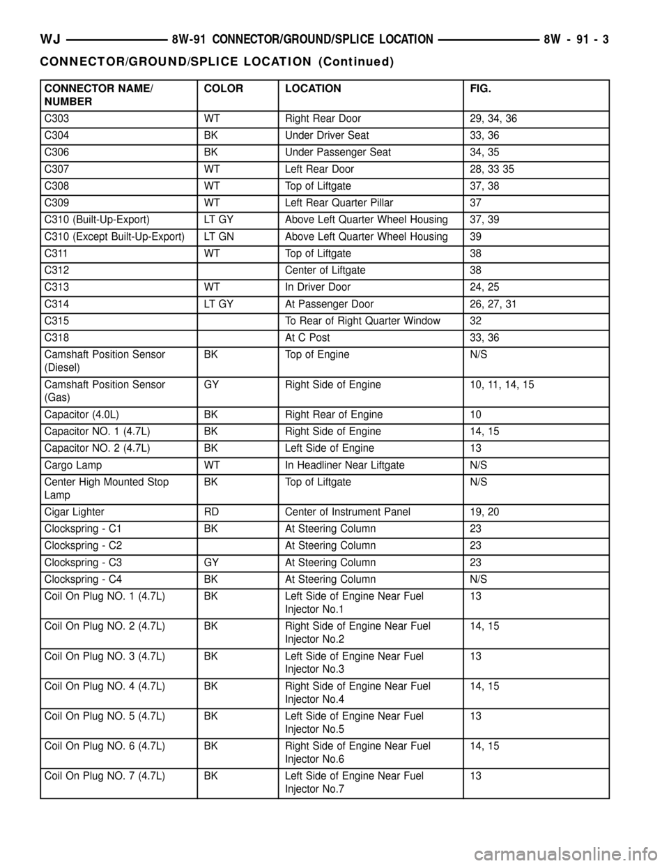
CONNECTOR NAME/
NUMBERCOLOR LOCATION FIG.
C303 WT Right Rear Door 29, 34, 36
C304 BK Under Driver Seat 33, 36
C306 BK Under Passenger Seat 34, 35
C307 WT Left Rear Door 28, 33 35
C308 WT Top of Liftgate 37, 38
C309 WT Left Rear Quarter Pillar 37
C310 (Built-Up-Export) LT GY Above Left Quarter Wheel Housing 37, 39
C310 (Except Built-Up-Export) LT GN Above Left Quarter Wheel Housing 39
C311 WT Top of Liftgate 38
C312 Center of Liftgate 38
C313 WT In Driver Door 24, 25
C314 LT GY At Passenger Door 26, 27, 31
C315 To Rear of Right Quarter Window 32
C318 At C Post 33, 36
Camshaft Position Sensor
(Diesel)BK Top of Engine N/S
Camshaft Position Sensor
(Gas)GY Right Side of Engine 10, 11, 14, 15
Capacitor (4.0L) BK Right Rear of Engine 10
Capacitor NO. 1 (4.7L) BK Right Side of Engine 14, 15
Capacitor NO. 2 (4.7L) BK Left Side of Engine 13
Cargo Lamp WT In Headliner Near Liftgate N/S
Center High Mounted Stop
LampBK Top of Liftgate N/S
Cigar Lighter RD Center of Instrument Panel 19, 20
Clockspring - C1 BK At Steering Column 23
Clockspring - C2 At Steering Column 23
Clockspring - C3 GY At Steering Column 23
Clockspring - C4 BK At Steering Column N/S
Coil On Plug NO. 1 (4.7L) BK Left Side of Engine Near Fuel
Injector No.113
Coil On Plug NO. 2 (4.7L) BK Right Side of Engine Near Fuel
Injector No.214, 15
Coil On Plug NO. 3 (4.7L) BK Left Side of Engine Near Fuel
Injector No.313
Coil On Plug NO. 4 (4.7L) BK Right Side of Engine Near Fuel
Injector No.414, 15
Coil On Plug NO. 5 (4.7L) BK Left Side of Engine Near Fuel
Injector No.513
Coil On Plug NO. 6 (4.7L) BK Right Side of Engine Near Fuel
Injector No.614, 15
Coil On Plug NO. 7 (4.7L) BK Left Side of Engine Near Fuel
Injector No.713
WJ8W-91 CONNECTOR/GROUND/SPLICE LOCATION 8W - 91 - 3
CONNECTOR/GROUND/SPLICE LOCATION (Continued)
Page 1179 of 2199
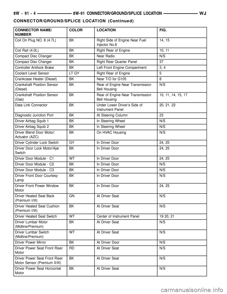
CONNECTOR NAME/
NUMBERCOLOR LOCATION FIG.
Coil On Plug NO. 8 (4.7L) BK Right Side of Engine Near Fuel
Injector No.814, 15
Coil Rail (4.0L) BK Right Rear of Engine 10, 11
Compact Disc Changer BK Near Radio N/S
Compact Disc Changer BK Right Rear Quarter Panel 37
Controller Antilock Brake BK Left Front Engine Compartment 3, 4
Coolant Level Sensor LT GY Right Rear of Engine 5
Crankcase Heater (Diesel) BK Near T/O for G105 8
Crankshaft Position Sensor
(Diesel)BK Rear of Engine Near Transmission
Bell HousingN/S
Crankshaft Position Sensor
(Gas)BK Rear of Engine Near Transmission
Bell Housing10, 11, 14, 15, 17
Data Link Connector BK Under Lower Driver's Side of
Instrument Panel20, 21, 22
Diagnostic Junction Port BK At Steering Column 23
Driver Airbag Squib 1 BK In Steering Wheel N/S
Driver Airbag Squib 2 BK In Steering Wheel N/S
Driver Blend Door Motor/
Actuator (AZC)BK On HVAC Housing N/S
Driver Cylinder Lock Switch GY In Driver Door 24, 25
Driver Door Lock Motor/Ajar
SwitchBK In Driver Door 24, 25
Driver Door Module - C1 WT In Driver Door 24, 25
Driver Door Module - C2 BK In Driver Door N/S
Driver Door Module - C3 BK In Driver Door N/S
Driver Front Door Courtesy
LampBK In Driver Door N/S
Driver Front Power Window
MotorBK In Driver Door 24, 25
Driver Heated Seat Back
(Premium I/III)GN At Driver Seat N/S
Driver Heated Seat Cushion
(Premium I/III)BK At Driver Seat N/S
Driver Heated Seat Switch WT Center of Instrument Panel 19 20, 21
Driver Lumbar Motor
(Midline/Premium)BK At Driver Seat N/S
Driver Lumbar Switch
(Midline/Premium)WT At Driver Seat N/S
Driver Power Mirror BK At Driver Door N/S
Driver Power Seat Front Riser
MotorRD At Driver Seat N/S
Driver Power Seat Front Riser
Motor Sensor (Premium II/III)BK At Driver Seat N/S
Driver Power Seat Horizontal
MotorBK At Driver Seat N/S
8W - 91 - 4 8W-91 CONNECTOR/GROUND/SPLICE LOCATIONWJ
CONNECTOR/GROUND/SPLICE LOCATION (Continued)
Page 1181 of 2199
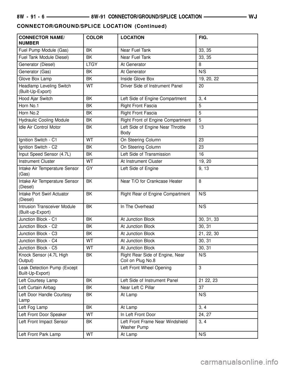
CONNECTOR NAME/
NUMBERCOLOR LOCATION FIG.
Fuel Pump Module (Gas) BK Near Fuel Tank 33, 35
Fuel Tank Module Diesel) BK Near Fuel Tank 33, 35
Generator (Diesel) LTGY At Generator 8
Generator (Gas) BK At Generator N/S
Glove Box Lamp BK Inside Glove Box 19, 20, 22
Headlamp Leveling Switch
(Built-Up-Export)WT Driver Side of Instrument Panel 20
Hood Ajar Switch BK Left Side of Engine Compartment 3, 4
Horn No.1 BK Right Front Fascia 5
Horn No.2 BK Right Front Fascia 5
Hydraulic Cooling Module BK Right Front of Engine Compartment 5
Idle Air Control Motor BK Left Side of Engine Near Throttle
Body13
Ignition Switch - C1 WT On Steering Column 23
Ignition Switch - C2 BK On Steering Column 23
Input Speed Sensor (4.7L) BK Left Side of Transmission 16
Instrument Cluster WT At Instrument Cluster 19, 20
Intake Air Temperature Sensor
(Gas)GY Left Side of Engine 9, 13
Intake Air Temperature Sensor
(Diesel)BK Near T/O for Crankcase Heater 8
Intake Port Swirl Actuator
(Diesel)BK Right Rear of Engine Compartment N/S
Intrusion Transceiver Module
(Built-up-Export)BK In The Overhead N/S
Junction Block - C1 BK At Junction Block 30, 31, 33
Junction Block - C2 BK At Junction Block 30, 31
Junction Block - C3 BK At Junction Block 21, 22, 30
Junction Block - C4 WT At Junction Block 30, 31
Junction Block - C5 WT At Junction Block 30, 31
Knock Sensor (4.7L High
Output)BK Right Rear Side of Engine, Near
Coil on Plug No.8N/S
Leak Detection Pump (Except
Built-Up-Export)Left Front Wheel Opening 3
Left Courtesy Lamp BK Left Side of Instrument Panel 21 22, 23
Left Curtain Airbag BK Near Left C Pillar 37
Left Door Handle Courtesy
LampBK At Lamp N/S
Left Fog Lamp BK At Lamp 3, 4
Left Front Door Speaker WT In Left Front Door 24, 27
Left Front Impact Sensor BK Left Front Frame Near Windshield
Washer Pump3, 4
Left Front Park Lamp WT At Lamp N/S
8W - 91 - 6 8W-91 CONNECTOR/GROUND/SPLICE LOCATIONWJ
CONNECTOR/GROUND/SPLICE LOCATION (Continued)
Page 1182 of 2199
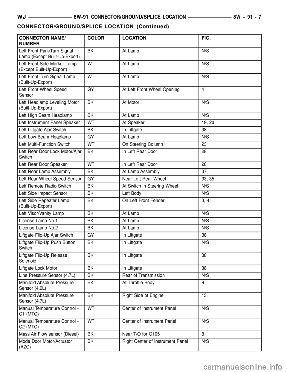
CONNECTOR NAME/
NUMBERCOLOR LOCATION FIG.
Left Front Park/Turn Signal
Lamp (Except Built-Up-Export)BK At Lamp N/S
Left Front Side Marker Lamp
(Except Built-Up-Export)WT At Lamp N/S
Left Front Turn Signal Lamp
(Built-Up-Export)WT At Lamp N/S
Left Front Wheel Speed
SensorGY At Left Front Wheel Opening 4
Left Headlamp Leveling Motor
(Built-Up-Export)BK At Motor N/S
Left High Beam Headlamp BK At Lamp N/S
Left Instrument Panel Speaker WT At Speaker 19, 20
Left Liftgate Ajar Switch BK In Liftgate 38
Left Low Beam Headlamp GY At Lamp N/S
Left Multi-Function Switch WT On Steering Column 23
Left Rear Door Lock Motor/Ajar
SwitchBK In Left Rear Door 28
Left Rear Door Speaker WT In Left Rear Door 28
Left Rear Lamp Assembly BK At Lamp Assembly 37
Left Rear Wheel Speed Sensor GY Near Left Rear Wheel 33, 35
Left Remote Radio Switch BK At Switch in Steering Wheel N/S
Left Side Impact Sensor BK Left Body N/S
Left Side Repeater Lamp
(Built-Up-Export)BK On Left Front Fender 3, 4
Left Visor/Vanity Lamp BK At Lamp N/S
License Lamp No.1 BK At Lamp N/S
License Lamp No.2 BK At Lamp N/S
Liftgate Flip-Up Ajar Switch GY In Liftgate 38
Liftgate Flip-Up Push Button
SwitchBK In Liftgate N/S
Liftgate Flip-Up Release
SolenoidBK In Liftgate 38
Liftgate Lock Motor BK In Liftgate 38
Line Pressure Sensor (4.7L) BK Rear of Transmission N/S
Manifold Absolute Pressure
Sensor (4.0L)BK At Throttle Body 9
Manifold Absolute Pressure
Sensor (4.7L)BK Right Side of Engine 13
Manual Temperature Control -
C1 (MTC)WT Center of Instrument Panel N/S
Manual Temperature Control -
C2 (MTC)WT Center of Instrument Panel N/S
Mass Air Flow sensor (Diesel) BK Near T/O for G105 8
Mode Door Motor/Actuator
(AZC)BK Right Center of Instrument Panel N/S
WJ8W-91 CONNECTOR/GROUND/SPLICE LOCATION 8W - 91 - 7
CONNECTOR/GROUND/SPLICE LOCATION (Continued)
Page 1185 of 2199
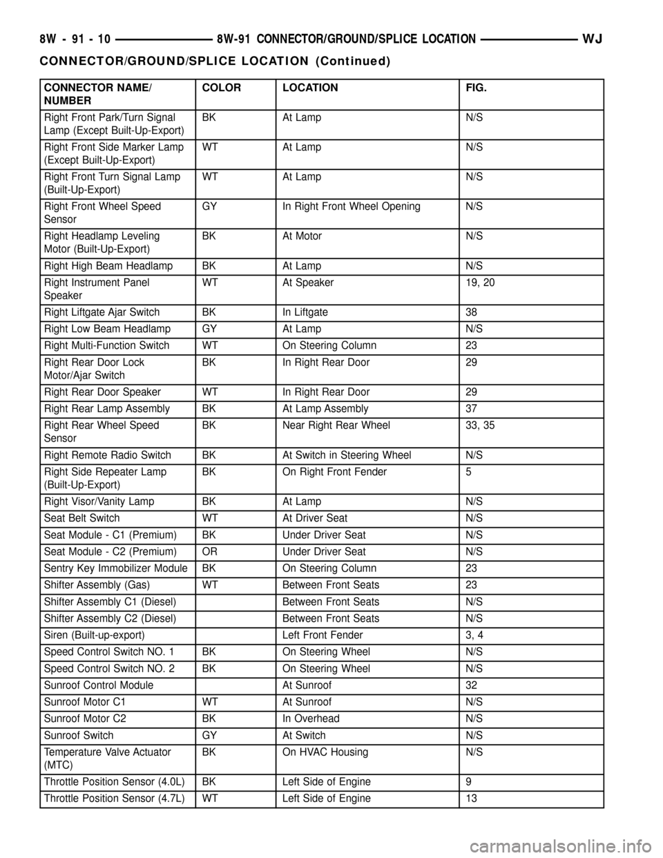
CONNECTOR NAME/
NUMBERCOLOR LOCATION FIG.
Right Front Park/Turn Signal
Lamp (Except Built-Up-Export)BK At Lamp N/S
Right Front Side Marker Lamp
(Except Built-Up-Export)WT At Lamp N/S
Right Front Turn Signal Lamp
(Built-Up-Export)WT At Lamp N/S
Right Front Wheel Speed
SensorGY In Right Front Wheel Opening N/S
Right Headlamp Leveling
Motor (Built-Up-Export)BK At Motor N/S
Right High Beam Headlamp BK At Lamp N/S
Right Instrument Panel
SpeakerWT At Speaker 19, 20
Right Liftgate Ajar Switch BK In Liftgate 38
Right Low Beam Headlamp GY At Lamp N/S
Right Multi-Function Switch WT On Steering Column 23
Right Rear Door Lock
Motor/Ajar SwitchBK In Right Rear Door 29
Right Rear Door Speaker WT In Right Rear Door 29
Right Rear Lamp Assembly BK At Lamp Assembly 37
Right Rear Wheel Speed
SensorBK Near Right Rear Wheel 33, 35
Right Remote Radio Switch BK At Switch in Steering Wheel N/S
Right Side Repeater Lamp
(Built-Up-Export)BK On Right Front Fender 5
Right Visor/Vanity Lamp BK At Lamp N/S
Seat Belt Switch WT At Driver Seat N/S
Seat Module - C1 (Premium) BK Under Driver Seat N/S
Seat Module - C2 (Premium) OR Under Driver Seat N/S
Sentry Key Immobilizer Module BK On Steering Column 23
Shifter Assembly (Gas) WT Between Front Seats 23
Shifter Assembly C1 (Diesel) Between Front Seats N/S
Shifter Assembly C2 (Diesel) Between Front Seats N/S
Siren (Built-up-export) Left Front Fender 3, 4
Speed Control Switch NO. 1 BK On Steering Wheel N/S
Speed Control Switch NO. 2 BK On Steering Wheel N/S
Sunroof Control Module At Sunroof 32
Sunroof Motor C1 WT At Sunroof N/S
Sunroof Motor C2 BK In Overhead N/S
Sunroof Switch GY At Switch N/S
Temperature Valve Actuator
(MTC)BK On HVAC Housing N/S
Throttle Position Sensor (4.0L) BK Left Side of Engine 9
Throttle Position Sensor (4.7L) WT Left Side of Engine 13
8W - 91 - 10 8W-91 CONNECTOR/GROUND/SPLICE LOCATIONWJ
CONNECTOR/GROUND/SPLICE LOCATION (Continued)
Page 1255 of 2199

(7) Remove the fan assembly from the water pump
(Refer to 7 - COOLING/ENGINE/RADIATOR FAN -
REMOVAL).
(8) Remove the fan shroud.
(9) Disconnect the transmission fluid cooler lines
(automatic transmission).
(10) Discharge the A/C system (Refer to 24 -
HEATING & AIR CONDITIONING/PLUMBING -
STANDARD PROCEDURE).
(11) Remove the service valves and cap the com-
pressor ports.
(12) Remove the radiator or radiator/condenser (if
equipped with A/C).
(13) Disconnect the heater hoses at the engine
thermostat housing and water pump.
(14) Disconnect the accelerator cable, transmission
line pressure cable and speed control cable (if
equipped) from the throttle body.
(15) Remove cables from the bracket and secure
out of the way.
(16) Disconnect the body ground at the engine.
(17) Disconnect the following connectors and
secure their harness out of the way.
²Power steering pressure switch
²Coolant temperature sensor
²Six (6) fuel injector connectors
²Intake air temperature sensor
²Throttle position sensor
²Map sensor
²Crankshaft position sensor
²Oxygen sensor
²Camshaft position sensor
²Generator connector and B+ terminal wire
(18) Disconnect the coil rail electrical connections
and the oil pressure switch connector.
(19) Perform the fuel pressure release procedure
(Refer to 14 - FUEL SYSTEM/FUEL DELIVERY -
STANDARD PROCEDURE).
(20) Disconnect the fuel supply line at the injector
rail (Refer to 14 - FUEL SYSTEM/FUEL DELIVERY/
QUICK CONNECT FITTING - STANDARD PROCE-
DURE).
(21) Remove the fuel line bracket from the intake
manifold.
(22) Remove the air cleaner assembly (Fig. 5).
(23) Disconnect the hoses from the fittings at the
steering gear.
(24) Drain the pump reservoir.
(25) Cap the fittings on the hoses and steering
gear to prevent foreign objects from entering the sys-
tem.
(26) Raise and support the vehicle.
(27) Disconnect the wires from the engine starter
motor solenoid.(28) Remove the engine starter motor (Refer to 8 -
ELECTRICAL/STARTING/STARTER MOTOR -
REMOVAL).
(29) Disconnect the oxygen sensor from the
exhaust pipe.
(30) Disconnect the exhaust pipe from the mani-
fold.
(31) Remove the exhaust pipe support.
(32) Remove the bending brace (Refer to 9 -
ENGINE/ENGINE BLOCK/STRUCT SUPPORT -
REMOVAL).
(33) Remove the engine flywheel/converter housing
access cover.
(34) Mark the converter and drive plate location.
(35) Remove the converter-to-drive plate bolts.
(36) Remove the upper engine flywheel/converter
housing bolts and loosen the bottom bolts.
(37) Remove the engine mount cushion-to-engine
compartment bracket bolts.
(38) Lower the vehicle.
(39) Attach a lifting device to the engine.
(40) Raise the engine off the front supports.
(41) Place a support or floor jack under the con-
verter (or engine flywheel) housing.
(42) Remove the remaining converter (or engine
flywheel) housing bolts.
(43) Lift the engine out of the engine compart-
ment.
Fig. 5 Air Cleaner Assembly
1 - POWER STEERING PUMP
2 - AIR CLEANER ASSEMBLY
9 - 12 ENGINE - 4.0LWJ
ENGINE - 4.0L (Continued)
Page 1256 of 2199

INSTALLATION
CAUTION: When installing the engine into a vehicle
equipped with an automatic transmission, be care-
ful not to damage the trigger wheel on the engine
flywheel.
(1) Attach a lifting device to the engine and lower
the engine into the engine compartment. For easier
installation, it may be necessary to remove the
engine mount bracket as an aid in alignment of the
engine to the transmission.
(2) Align the transmission torque converter hous-
ing with the engine.
(3) Loosely install the converter housing lower
bolts and install the next higher bolt and nut on each
side.
(4) Tighten all 4 bolts finger tight.
(5) Install the engine mount brackets (if removed).
(6) Lower the engine and engine mount brackets
onto the engine compartment cushions. Install the
bolts and finger tighten the nuts.
(7) Remove the engine lifting device.
(8) Raise and support the vehicle.
(9) Install the remaining engine flywheel/converter
housing bolts. Tighten all bolts to 38 N´m (28 ft. lbs.)
torque.
(10) Install the converter-to-drive plate bolts.
(11) Ensure the installation reference marks are
aligned.
(12) Install the engine flywheel/converter housing
access cover.
(13) Install the exhaust pipe support and tighten
the screw.
(14) Install the engine bending brace (Refer to 9 -
ENGINE/ENGINE BLOCK/STRUCT SUPPORT -
INSTALLATION).
(15) Tighten the engine mount-to-bracket bolts.
(16) Connect the vehicle speed sensor wire connec-
tions and tighten the screws.
(17) Connect the exhaust pipe to the manifold.
(18) Install the engine starter motor (Refer to 8 -
ELECTRICAL/STARTING/STARTER MOTOR -
INSTALLATION).
(19) Connect the wires to the engine starter motor
solenoid.
(20) Lower the vehicle.
(21) Connect all the vacuum hoses and wire con-
nectors identified during engine removal.
(22) Remove protective caps from the power steer-
ing hoses.
(23) Connect the hoses to the fittings at the steer-
ing gear. Tighten the nut to 52 N´m (38 ft. lbs.)
torque.
(24) Fill the pump reservoir with fluid.(25) Inspect the fuel supply line o-ring(s) and
replace if necessary. Connect fuel supply line to injec-
tior rail and verify connection by pulling outward on
the line.
(26) Install the fuel line bracket to the intake
manifold.
(27) Connect the coil rail electrical connectors and
oil pressure switch connector.
(28) Connect the following electrical connectors:
²Power steering pressure switch
²Coolant temperature sensor
²Six (6) fuel injector connectors
²Intake air temperature sensor
²Throttle position sensor
²Map sensor
²Crankshaft position sensor
²Oxygen sensor
²Camshaft position sensor
²Generator connector and B+ terminal wire
(29) Connect all previously removed vacuum hoses.
(30) Connect the body ground strap.
(31) Install the throttle, transmission line pres-
sure, and speed control cables to their mounting
bracket and connect them to the throttle body.
(32) Connect the heater hoses at the engine ther-
mostat housing and water pump.
(33) Install the fan assembly (Refer to 7 - COOL-
ING/ENGINE/RADIATOR FAN - INSTALLATION).
(34) Place the fan shroud in position over the fan.
(35) Install the radiator (Refer to 7 - COOLING/
ENGINE/RADIATOR - INSTALLATION).
(36) Connect the service valves to the A/C com-
pressor ports, if equipped with A/C.
(37) Charge the air conditioner system (Refer to 24
- HEATING & AIR CONDITIONING/PLUMBING -
STANDARD PROCEDURE).
(38) Connect the radiator hoses and automatic
transmission fluid cooler pipes, if equipped.
(39) Install the fan shroud to the radiator or radi-
ator/condenser (if equipped with A/C).
(40) Install upper radiator support.
(41) Connect the upper radiator hose and tighten
the clamp.
(42) Connect the lower radiator hose and tighten
the clamp.
(43) Fill crankcase with engine oil. (Refer to
LUBRICATION & MAINTENANCE/FLUID CAPACI-
TIES - SPECIFICATIONS) for correct capacities.
(44) Fill the cooling system with reusable coolant
or new coolant (Refer to 7 - COOLING - STANDARD
PROCEDURE).
(45) Align the hood to the scribe marks. Install the
hood.
(46) Install the air cleaner assembly.
(47) Install the battery and connect the battery
cable.
WJENGINE - 4.0L 9 - 13
ENGINE - 4.0L (Continued)