Battery cable JEEP GRAND CHEROKEE 2003 WJ / 2.G Workshop Manual
[x] Cancel search | Manufacturer: JEEP, Model Year: 2003, Model line: GRAND CHEROKEE, Model: JEEP GRAND CHEROKEE 2003 WJ / 2.GPages: 2199, PDF Size: 76.01 MB
Page 18 of 2199

JUMP STARTING
STANDARD PROCEDURE - JUMP STARTING
WARNING: REVIEW ALL SAFETY PRECAUTIONS
AND WARNINGS IN GROUP 8A, BATTERY/START-
ING/CHARGING SYSTEMS DIAGNOSTICS. DO NOT
JUMP START A FROZEN BATTERY, PERSONAL
INJURY CAN RESULT. DO NOT JUMP START WHEN
MAINTENANCE FREE BATTERY INDICATOR DOT IS
YELLOW OR BRIGHT COLOR. DO NOT JUMP
START A VEHICLE WHEN THE BATTERY FLUID IS
BELOW THE TOP OF LEAD PLATES. DO NOT
ALLOW JUMPER CABLE CLAMPS TO TOUCH
EACH OTHER WHEN CONNECTED TO A BOOSTER
SOURCE. DO NOT USE OPEN FLAME NEAR BAT-
TERY. REMOVE METALLIC JEWELRY WORN ON
HANDS OR WRISTS TO AVOID INJURY BY ACCI-
DENTAL ARCING OF BATTERY CURRENT. WHEN
USING A HIGH OUTPUT BOOSTING DEVICE, DO
NOT ALLOW BATTERY VOLTAGE TO EXCEED 16
VOLTS. REFER TO INSTRUCTIONS PROVIDED
WITH DEVICE BEING USED.
CAUTION: When using another vehicle as a
booster, do not allow vehicles to touch. Electrical
systems can be damaged on either vehicle.
TO JUMP START A DISABLED VEHICLE:
(1) Raise hood on disabled vehicle and visually
inspect engine compartment for:
²Battery cable clamp condition, clean if necessary.
²Frozen battery.
²Yellow or bright color test indicator, if equipped.
²Low battery fluid level.
²Generator drive belt condition and tension.
²Fuel fumes or leakage, correct if necessary.
CAUTION: If the cause of starting problem on dis-
abled vehicle is severe, damage to booster vehicle
charging system can result.
(2) When using another vehicle as a booster
source, park the booster vehicle within cable reach.
Turn off all accessories, set the parking brake, place
the automatic transmission in PARK or the manual
transmission in NEUTRAL and turn the ignition
OFF.
(3) On disabled vehicle, place gear selector in park
or neutral and set park brake. Turn off all accesso-
ries.
(4) Connect jumper cables to booster battery. RED
clamp to positive terminal (+). BLACK clamp to neg-
ative terminal (-). DO NOT allow clamps at opposite
end of cables to touch, electrical arc will result.
Review all warnings in this procedure.
(5) On disabled vehicle, connect RED jumper cable
clamp to positive (+) terminal. Connect BLACK
jumper cable clamp to engine ground as close to the
ground cable attaching point as possible (Fig. 8).
(6) Start the engine in the vehicle which has the
booster battery, let the engine idle a few minutes,
then start the engine in the vehicle with the dis-
charged battery.
CAUTION: Do not crank starter motor on disabled
vehicle for more than 15 seconds, starter will over-
heat and could fail.
(7) Allow battery in disabled vehicle to charge to
at least 12.4 volts (75% charge) before attempting to
start engine. If engine does not start within 15 sec-
onds, stop cranking engine and allow starter to cool
(15 min.), before cranking again.
Fig. 7 Correct Vehicle Lifting Locations
WJLUBRICATION & MAINTENANCE 0 - 7
LIFT POINTS (Continued)
Page 19 of 2199

DISCONNECT CABLE CLAMPS AS FOLLOWS:
²Disconnect BLACK cable clamp from engine
ground on disabled vehicle.
²When using a Booster vehicle, disconnect
BLACK cable clamp from battery negative terminal.
Disconnect RED cable clamp from battery positive
terminal.
²Disconnect RED cable clamp from battery posi-
tive terminal on disabled vehicle.
EMERGENCY TOW HOOKS
DESCRIPTION
WARNING: REMAIN AT A SAFE DISTANCE FROM A
VEHICLE THAT IS BEING TOWED VIA ITS TOW
HOOKS. THE TOW STRAPS/CHAINS COULD BREAK
AND CAUSE SERIOUS INJURY.
Some Jeep vehicles are equipped with front emer-
gency tow hooks (Fig. 9). The tow hooks should be
used forEMERGENCYpurposes only.
CAUTION: DO NOT use emergency tow hooks for
tow truck hook-up or highway towing.
TOWING
STANDARD PROCEDURE - TOWING
RECOMMENDATIONS
A vehicle equipped with SAE approved wheel lift-
type towing equipment can be used to tow WJ vehi-
cles. When towing a 4WD vehicle using a wheel-lift
towing device, use tow dollies under the opposite end
of the vehicle. A vehicle with flatbed device can also
be used to transport a disabled vehicle (Fig. 10).
SAFETY PRECAUTIONS
CAUTION: The following safety precautions must be
observed when towing a vehicle:
²Secure loose and protruding parts.
²Always use a safety chain system that is inde-
pendent of the lifting and towing equipment.
Fig. 8 Jumper Cable Clamp Connections
1 - ENGINE GROUND
2 - NEGATIVE JUMPER CABLE
3 - BATTERY NEGATIVE CABLE
4 - POSITIVE JUMPER CABLE
5 - BATTERY POSITIVE CABLE
6 - BATTERY
7 - TEST INDICATOR
Fig. 9 Emergency Tow Hooks
1 - TOW HOOK
Fig. 10 Tow Vehicles With Approved Equipment
0 - 8 LUBRICATION & MAINTENANCEWJ
JUMP STARTING (Continued)
Page 202 of 2199

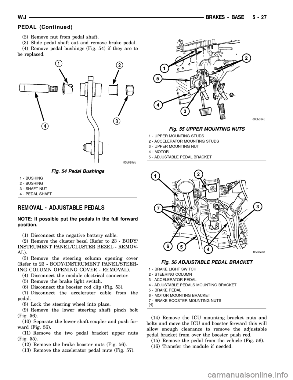
(2) Remove nut from pedal shaft.
(3) Slide pedal shaft out and remove brake pedal.
(4) Remove pedal bushings (Fig. 54) if they are to
be replaced.
REMOVAL - ADJUSTABLE PEDALS
NOTE: If possible put the pedals in the full forward
position.
(1) Disconnect the negative battery cable.
(2) Remove the cluster bezel (Refer to 23 - BODY/
INSTRUMENT PANEL/CLUSTER BEZEL - REMOV-
AL).
(3) Remove the steering column opening cover
(Refer to 23 - BODY/INSTRUMENT PANEL/STEER-
ING COLUMN OPENING COVER - REMOVAL).
(4) Disconnect the module electrical connector.
(5) Remove the brake light switch.
(6) Disconnect the booster rod clip (Fig. 53).
(7) Disconnect the accelerator cable from the
pedal.
(8) Lock the steering wheel into place.
(9) Remove the lower steering shaft pinch bolt
(Fig. 56).
(10) Separate the lower shaft coupler and push for-
ward (Fig. 56).
(11) Remove the two pedal bracket upper nuts
(Fig. 55).
(12) Remove the brake booster nuts (Fig. 56).
(13) Remove the accelerator pedal nuts (Fig. 57).(14) Remove the ICU mounting bracket nuts and
bolts and move the ICU and booster forward this will
allow enough clearance to remove the adjustable
pedal bracket from over the booster push rod.
(15) Remove the pedal from the vehicle (Fig. 56).
(16) Transfer the module if needed.
Fig. 54 Pedal Bushings
1 - BUSHING
2 - BUSHING
3 - SHAFT NUT
4 - PEDAL SHAFT
Fig. 55 UPPER MOUNTING NUTS
1 - UPPER MOUNTING STUDS
2 - ACCELERATOR MOUNTING STUDS
3 - UPPER MOUNTING NUT
4 - MOTOR
5 - ADJUSTABLE PEDAL BRACKET
Fig. 56 ADJUSTABLE PEDAL BRACKET
1 - BRAKE LIGHT SWITCH
2 - STEERING COLUMN
3 - ACCELERATOR PEDAL
4 - ADJUSTABLE PEDALS MOUNTING BRACKET
5 - BRAKE PEDAL
6 - MOTOR MOUNTING BRACKET
7 - BRAKE BOOSTER MOUNTING NUTS
(4)
WJBRAKES - BASE 5 - 27
PEDAL (Continued)
Page 203 of 2199

INSTALLATION
INSTALLATION - NON-ADJUSTABLE PEDAL
(1) Lubricate bushings, pedal shaft and pedal pin
with Mopar multi-mileage grease.
(2) Install bushings into pedal.
(3) Position pedal in bracket and install pedal
shaft in support and through pedal.
(4) Install new nut on pedal shaft and tighten to
27 N´m (20 ft. lbs.).
NOTE: Pedal shaft nut should not be reused.
(5) Install booster push rod on pedal pin and
install retainer clip on pedal pin.
(6) Check and adjust stop lamp switch if necessary.
INSTALLATION - ADJUSTABLE PEDALS
(1) Install the pedal to the vehicle (Fig. 56).
(2) Reposition the ICU and booster, Install the
ICU mounting bracket nuts and bolts.
28 N
(3) Install the brake booster nuts. Tighten to 28
N´m ( 21 ft. lbs.). (Fig. 56).
(4) Install the pedal bracket upper nuts. Tighten
to 12 N´m ( 9 ft. lbs.). (Fig. 56).
(5) Install the accelerator pedal nuts. Tighten to
28 N´m ( 21 ft. lbs.). (Fig. 57).
(6) Install the lower steering shaft coupler over the
shaft (Fig. 56).
(7) Install the lower steering shaft pinch bolt (Fig.
56).
(8) Unlock the steering wheel.
(9) Reconnect the accelerator cable to the pedal
(Fig. 56).(10) Reconnect the booster rod clip (Fig. 56).
(11) Install the brake light switch.
(12) Reconnect the module electrical connector.
(13) Install the steering column opening cover
(Refer to 23 - BODY/INSTRUMENT PANEL/STEER-
ING COLUMN OPENING COVER - INSTALLA-
TION).
(14) Install the cluster bezel (Refer to 23 - BODY/
INSTRUMENT PANEL/CLUSTER BEZEL -
INSTALLATION).
(15) Reconnect the negative battery cable.
PEDAL MOTOR
REMOVAL
(1) Disconnect the negative battery cable.
(2) Remove the cluster bezel (Refer to 23 - BODY/
INSTRUMENT PANEL/CLUSTER BEZEL - REMOV-
AL).
(3) Remove the steering column opening cover
(Refer to 23 - BODY/INSTRUMENT PANEL/STEER-
ING COLUMN OPENING COVER - REMOVAL).
(4) Remove the two mounting screws (Fig. 58).
(5) Disconnect the electrical connector (Fig. 58).
(6) Remove the adjustable pedal motor (Fig. 58).
INSTALLATION
(1) Install the adjustable pedal motor (Fig. 58).
(2) Reconnect the electrical connector (Fig. 58).
(3) Install the two mounting screws (Fig. 58).
(4) Install the steering column opening cover
(Refer to 23 - BODY/INSTRUMENT PANEL/STEER-
ING COLUMN OPENING COVER - INSTALLA-
TION).
Fig. 57 ACCELERATOR MOUNTING BRACKET
1 - ACCELERATOR MOUNTING NUTS
2 - ADJUSTABLE PEDALS BRACKET
3 - ACCELERATOR PEDAL
Fig. 58 ADJUSTABLE PEDALS MOTOR
1 - ELECTRICAL CONNECTOR
2 - PEDALS MOTOR
3 - MOUNTING SCREWS HOLES
5 - 28 BRAKES - BASEWJ
PEDAL (Continued)
Page 204 of 2199

(5) Install the cluster bezel (Refer to 23 - BODY/
INSTRUMENT PANEL/CLUSTER BEZEL -
INSTALLATION).
(6) Reconnect the negative battery cable.
POWER BRAKE BOOSTER
DESCRIPTION
The booster assembly consists of a housing divided
into separate chambers by two internal diaphragms.
The outer edge of each diaphragm is attached to the
booster housing.
Two push rods are used in the booster. The pri-
mary push rod connects the booster to the brake
pedal. The secondary push rod connects the booster
to the master cylinder to stroke the cylinder pistons.
OPERATION
The atmospheric inlet valve is opened and closed
by the primary push rod. Booster vacuum supply is
through a hose attached to an intake manifold fittingat one end and to the booster check valve at the
other. The vacuum check valve in the booster housing
is a one-way device that prevents vacuum leak back.
Power assist is generated by utilizing the pressure
differential between normal atmospheric pressure
and a vacuum. The vacuum needed for booster oper-
ation is taken directly from the engine intake mani-
fold. The entry point for atmospheric pressure is
through a filter and inlet valve at the rear of the
housing (Fig. 59) .
The chamber areas forward of the booster dia-
phragms are exposed to vacuum from the intake
manifold. The chamber areas to the rear of the dia-
phragms, are exposed to normal atmospheric pres-
sure of 101.3 kilopascals (14.7 pounds/square in.).
Brake pedal application causes the primary push
rod to open the atmospheric inlet valve. This exposes
the area behind the diaphragms to atmospheric pres-
sure. The resulting pressure differential provides the
extra apply force for power assist.
The booster check valve, check valve grommet and
booster seals are serviceable.
WJBRAKES - BASE 5 - 29
PEDAL MOTOR (Continued)
Page 222 of 2199

PRESSURE HOLD
Both solenoid valves are closed in the pressure
hold cycle. Fluid apply pressure in the control chan-
nel is maintained at a constant rate. The CAB main-
tains the hold cycle until sensor inputs indicate a
pressure change is necessary.
PRESSURE INCREASE
The inlet valve is open and the outlet valve is
closed during the pressure increase cycle. The pres-
sure increase cycle is used to counteract unequal
wheel speeds. This cycle controls re-application of
fluid apply pressure due to changing road surfaces or
wheel speed.
REMOVAL
(1) Remove the negative battery cable from the
battery.
(2) Remove the air cleaner housing,(Refer to 9 -
ENGINE/AIR INTAKE SYSTEM/AIR CLEANER
HOUSING - REMOVAL).
(3) Pull the CAB harness connector release up and
remove connector (Fig. 10).(4) Remove the brake lines from the HCU.
(5) Remove the HCU/CAB side mounting bolt and
the two rear mounting bolts. (Fig. 11).
(6) Remove the HCU/CAB assembly from the vehi-
cle.
INSTALLATION
(1) Install HCU/CAB assembly into the mounting
bracket and tighten mounting bolts to 12 N´m (9 ft.
lbs.).
(2) Install the brake lines to the HCU and tighten
to 16 N´m (12 ft. lbs.).
(3) Install CAB harness connector and push down
connector release.
(4) Install air cleaner housing,(Refer to 9 -
ENGINE/AIR INTAKE SYSTEM/AIR CLEANER
HOUSING - INSTALLATION).
(5) Install negative battery cable to the battery.
(6) Bleed base and ABS brake systems,(Refer to 5 -
BRAKES - STANDARD PROCEDURE) OR (Refer to
5 - BRAKES - STANDARD PROCEDURE).
Fig. 10 CAB Connector Release
1 - CONNECTOR RELEASE
2 - CAB
Fig. 11 HCU/CAB Assembly
1 - SIDE MOUNTING BOLT
2 - REAR MOUNTING BOLTS
WJBRAKES - ABS 5 - 47
HCU (HYDRAULIC CONTROL UNIT) (Continued)
Page 242 of 2199

CONDITION POSSIBLE CAUSES CORRECTION
BELT BROKEN (NOTE: IDENTIFY
AND CORRECT PROBLEM
BEFORE NEW BELT IS
INSTALLED)1. Excessive tension. 1. Replace belt and automatic belt
tensioner.
2. Incorrect belt. 2. Replace belt.
3. Tensile member damaged during
belt installation.3. Replace belt.
4. Severe misalignment. 4. Check and replace.
5. Bracket, pulley, or bearing failure. 5. Replace defective component
and belt.
NOISE (OBJECTIONABLE
SQUEAL, SQUEAK, OR RUMBLE
IS HEARD OR FELT WHILE
DRIVE BELT IS IN OPERATION)1. Belt slippage. 1. Replace belt or automatic belt
tensioner.
2. Bearing noise. 2. Locate and repair.
3. Belt misalignment. 3. Replace belt.
4. Belt-to-pulley mismatch. 4. Install correct belt.
REMOVALÐ4.0L ENGINE
NOTE: The belt routing schematics are published
from the latest information available at the time of
publication. If anything differs between these sche-
matics and the Belt Routing Label, use the sche-
matics on Belt Routing Label. This label is located
in the engine compartment.
CAUTION: DO NOT LET TENSIONER ARM SNAP
BACK TO THE FREEARM POSITION, SEVERE DAM-
AGE MAY OCCUR TO THE TENSIONER.
Belt tension is not adjustable. Belt adjustment is
maintained by an automatic ( spring load ) belt ten-
sioner.
(1) Disconnect negative battery cable from battery.
(2) Rotate belt tensioner until it contacts its stop.
Remove belt, then slowly rotate the tensioner into
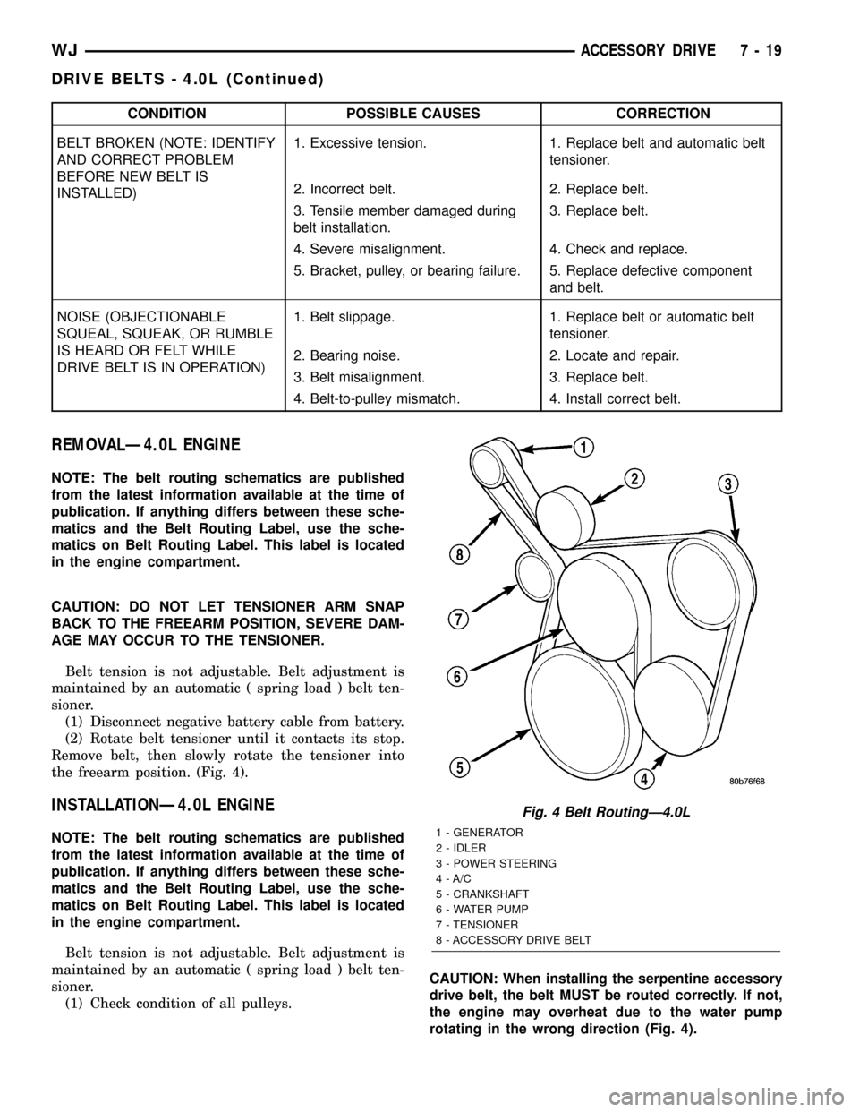
the freearm position. (Fig. 4).
INSTALLATIONÐ4.0L ENGINE
NOTE: The belt routing schematics are published
from the latest information available at the time of
publication. If anything differs between these sche-
matics and the Belt Routing Label, use the sche-
matics on Belt Routing Label. This label is located
in the engine compartment.
Belt tension is not adjustable. Belt adjustment is
maintained by an automatic ( spring load ) belt ten-
sioner.
(1) Check condition of all pulleys.CAUTION: When installing the serpentine accessory
drive belt, the belt MUST be routed correctly. If not,
the engine may overheat due to the water pump
rotating in the wrong direction (Fig. 4).
Fig. 4 Belt RoutingÐ4.0L
1 - GENERATOR
2 - IDLER
3 - POWER STEERING
4 - A/C
5 - CRANKSHAFT
6 - WATER PUMP
7 - TENSIONER
8 - ACCESSORY DRIVE BELT
WJACCESSORY DRIVE 7 - 19
DRIVE BELTS - 4.0L (Continued)
Page 245 of 2199

CONDITION POSSIBLE CAUSES CORRECTION
BELT BROKEN (NOTE: IDENTIFY
AND CORRECT PROBLEM
BEFORE NEW BELT IS
INSTALLED)1. Excessive tension. 1. Replace belt and automatic belt
tensioner.
2. Incorrect belt. 2. Replace belt.
3. Tensile member damaged during
belt installation.3. Replace belt.
4. Severe misalignment. 4. Check and replace.
5. Bracket, pulley, or bearing failure. 5. Replace defective component
and belt.
NOISE (OBJECTIONABLE
SQUEAL, SQUEAK, OR RUMBLE
IS HEARD OR FELT WHILE
DRIVE BELT IS IN OPERATION)1. Belt slippage. 1. Replace belt or automatic belt
tensioner.
2. Bearing noise. 2. Locate and repair.
3. Belt misalignment. 3. Replace belt.
4. Belt-to-pulley mismatch. 4. Install correct belt.
REMOVAL - 4.7L ENGINE
NOTE: The belt routing schematics are published
from the latest information available at the time of
publication. If anything differs between these sche-
matics and the Belt Routing Label, use the sche-
matics on Belt Routing Label. This label is located
in the engine compartment.
CAUTION: DO NOT LET TENSIONER ARM SNAP
BACK TO THE FREEARM POSITION, SEVERE DAM-
AGE MAY OCCUR TO THE TENSIONER.
Belt tension is not adjustable. Belt adjustment is
maintained by an automatic ( spring load ) belt ten-
sioner.
(1) Disconnect negative battery cable from battery.
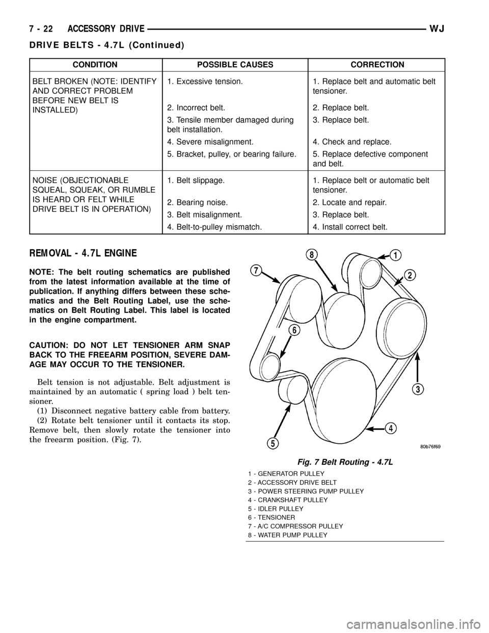
(2) Rotate belt tensioner until it contacts its stop.
Remove belt, then slowly rotate the tensioner into
the freearm position. (Fig. 7).
Fig. 7 Belt Routing - 4.7L
1 - GENERATOR PULLEY
2 - ACCESSORY DRIVE BELT
3 - POWER STEERING PUMP PULLEY
4 - CRANKSHAFT PULLEY
5 - IDLER PULLEY
6 - TENSIONER
7 - A/C COMPRESSOR PULLEY
8 - WATER PUMP PULLEY
7 - 22 ACCESSORY DRIVEWJ
DRIVE BELTS - 4.7L (Continued)
Page 254 of 2199

NOTE: When ever the high pressure line fittings are
removed from the hydraulic fan drive the o-rings
located on the fittings must be replaced.
(7) Lubricate the o-rings on the fittings with power
steering fluid then connect inlet and outlet high pres-
sure lines to fan drive (Fig. 9). Tighten inlet line to
49 N´m (36 ft. lbs.) tighten outlet line to 29 N´m (21.5
ft. lbs.).
(8) Connect low pressure return hose to fan drive
(Fig. 9).
(9) Lower vehicle.
(10) Install radiator upper hose.
(11) Connect electrical connector for hydraulic fan
control solenoid.
(12) Tighten fan shroud upper mounting bolts to 6
N´m (50 in. lbs.).
(13) Refill cooling system (Refer to 7 - COOLING -
STANDARD PROCEDURE).
CAUTION: Do not run engine with power steering
fluid below the full mark in the reservoir. Sever
damage to the hydraulic cooling fan or the engine
can occur.(14) Refill power steering fluid reservoir and bleed
air from steering system (Refer to 19 - STEERING/
PUMP - STANDARD PROCEDURE).
(15) Run engine and check for leaks.
RADIATOR FAN - 4.0L
DESCRIPTION
The radiator cooling fan used on the 4.0L engine is
an hybrid fan design. The hybrid fan system consist
of a low speed viscous driven mechanical fan and a
electrical fan (Fig. 10).
REMOVAL
(1) Disconnect negative battery cable from battery.
(2) The thermal viscous fan drive/fan blade assem-
bly is attached (threaded) to water pump hub shaft.
Remove fan blade/viscous fan drive assembly from
water pump by turning mounting nut counterclock-
wise as viewed from front (Fig. 11). Threads on vis-
cous fan drive areRIGHT HAND.
(3) Do not attempt to remove fan/viscous fan drive
assembly from vehicle at this time.
(4) Do not unbolt fan blade assembly from viscous
fan drive at this time.
(5) Remove fan shroud-to-upper crossmember nuts.
(6) Remove fan shroud and fan blade/viscous fan
drive assembly as a complete unit from vehicle.
Fig. 9 HYDRAULIC LINES/HOSES AND ELECTRICAL
CONNECTOR
1 - LOW PRESSURE RETURN HOSE
2 - HIGH PRESSURE LINE (OUTLET)
3 - HIGH PRESSURE LINE (INLET)
4 - HYDRAULIC FAN DRIVEFig. 10 Radiator Cooling Fan
1 - RADIATOR
2 - ELECTRIC COOLING FAN CONNECTOR
3 - FAN SHROUD
4 - ELECTRIC COOLING FAN
WJENGINE 7 - 31
RADIATOR FAN - 4.7L (Continued)
Page 256 of 2199

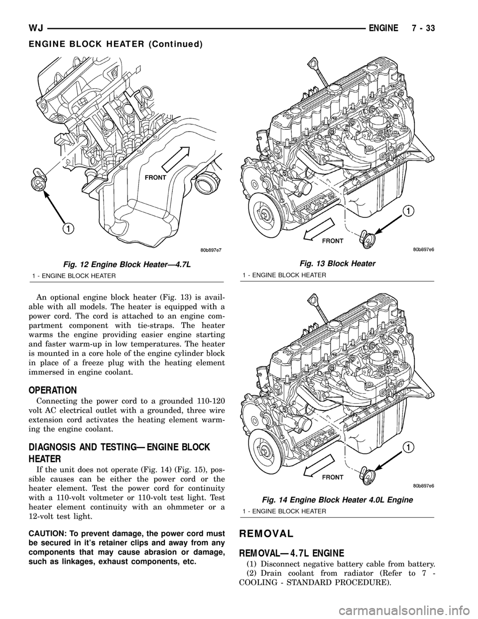
An optional engine block heater (Fig. 13) is avail-
able with all models. The heater is equipped with a
power cord. The cord is attached to an engine com-
partment component with tie-straps. The heater
warms the engine providing easier engine starting
and faster warm-up in low temperatures. The heater
is mounted in a core hole of the engine cylinder block
in place of a freeze plug with the heating element
immersed in engine coolant.
OPERATION
Connecting the power cord to a grounded 110-120
volt AC electrical outlet with a grounded, three wire
extension cord activates the heating element warm-
ing the engine coolant.
DIAGNOSIS AND TESTINGÐENGINE BLOCK
HEATER
If the unit does not operate (Fig. 14) (Fig. 15), pos-
sible causes can be either the power cord or the
heater element. Test the power cord for continuity
with a 110-volt voltmeter or 110-volt test light. Test
heater element continuity with an ohmmeter or a
12-volt test light.
CAUTION: To prevent damage, the power cord must
be secured in it's retainer clips and away from any
components that may cause abrasion or damage,
such as linkages, exhaust components, etc.
REMOVAL
REMOVALÐ4.7L ENGINE
(1) Disconnect negative battery cable from battery.
(2) Drain coolant from radiator (Refer to 7 -
COOLING - STANDARD PROCEDURE).
Fig. 12 Engine Block HeaterÐ4.7L
1 - ENGINE BLOCK HEATER
Fig. 13 Block Heater
1 - ENGINE BLOCK HEATER
Fig. 14 Engine Block Heater 4.0L Engine
1 - ENGINE BLOCK HEATER
WJENGINE 7 - 33
ENGINE BLOCK HEATER (Continued)