bore JEEP GRAND CHEROKEE 2003 WJ / 2.G Workshop Manual
[x] Cancel search | Manufacturer: JEEP, Model Year: 2003, Model line: GRAND CHEROKEE, Model: JEEP GRAND CHEROKEE 2003 WJ / 2.GPages: 2199, PDF Size: 76.01 MB
Page 53 of 2199
SINGLE CARDAN UNIVERSAL
JOINTS
DISASSEMBLY
NOTE: Individual components of cardan universal
joints are not serviceable. If worn or leaking, they
must be replaced as an assembly.
(1) Remove the propeller shaft.
(2) Tap the outside of the bearing cap assembly
with a drift to loosen snap ring.
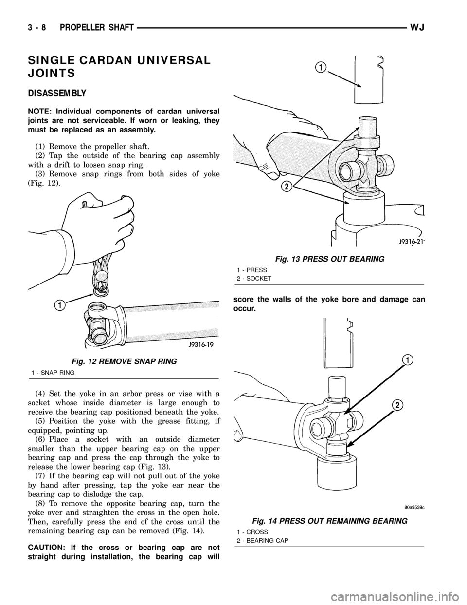
(3) Remove snap rings from both sides of yoke
(Fig. 12).
(4) Set the yoke in an arbor press or vise with a
socket whose inside diameter is large enough to
receive the bearing cap positioned beneath the yoke.
(5) Position the yoke with the grease fitting, if
equipped, pointing up.
(6) Place a socket with an outside diameter
smaller than the upper bearing cap on the upper
bearing cap and press the cap through the yoke to
release the lower bearing cap (Fig. 13).
(7) If the bearing cap will not pull out of the yoke
by hand after pressing, tap the yoke ear near the
bearing cap to dislodge the cap.
(8) To remove the opposite bearing cap, turn the
yoke over and straighten the cross in the open hole.
Then, carefully press the end of the cross until the
remaining bearing cap can be removed (Fig. 14).
CAUTION: If the cross or bearing cap are not
straight during installation, the bearing cap willscore the walls of the yoke bore and damage can
occur.
Fig. 12 REMOVE SNAP RING
1 - SNAP RING
Fig. 13 PRESS OUT BEARING
1 - PRESS
2 - SOCKET
Fig. 14 PRESS OUT REMAINING BEARING
1 - CROSS
2 - BEARING CAP
3 - 8 PROPELLER SHAFTWJ
Page 54 of 2199
ASSEMBLY
(1) Apply extreme pressure (EP) N.L.G.I. Grade 1
or 2 grease to inside of yoke bores.
(2) Position the cross in the yoke with its lube fit-
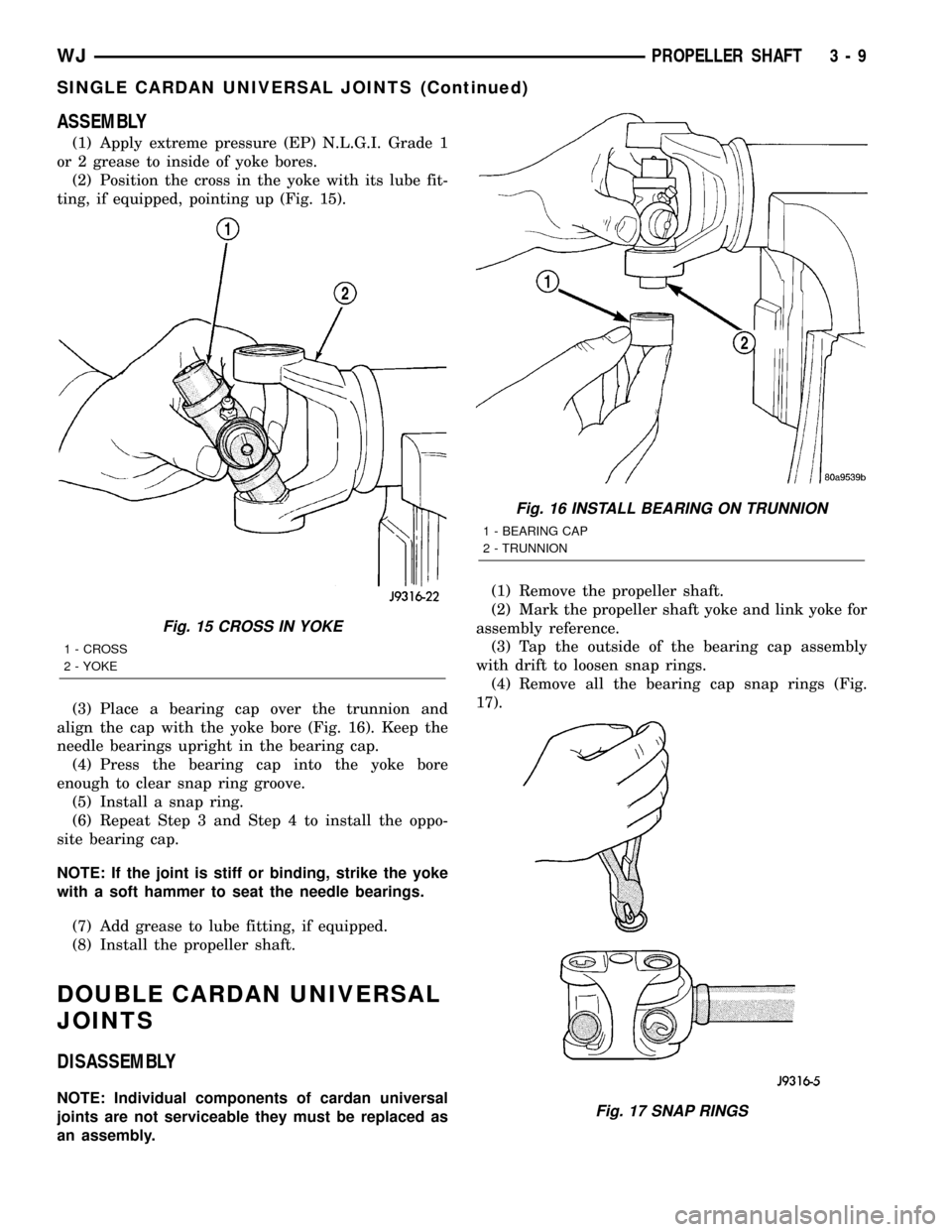
ting, if equipped, pointing up (Fig. 15).
(3) Place a bearing cap over the trunnion and
align the cap with the yoke bore (Fig. 16). Keep the
needle bearings upright in the bearing cap.
(4) Press the bearing cap into the yoke bore
enough to clear snap ring groove.
(5) Install a snap ring.
(6) Repeat Step 3 and Step 4 to install the oppo-
site bearing cap.
NOTE: If the joint is stiff or binding, strike the yoke
with a soft hammer to seat the needle bearings.
(7) Add grease to lube fitting, if equipped.
(8) Install the propeller shaft.
DOUBLE CARDAN UNIVERSAL
JOINTS
DISASSEMBLY
NOTE: Individual components of cardan universal
joints are not serviceable they must be replaced as
an assembly.(1) Remove the propeller shaft.
(2) Mark the propeller shaft yoke and link yoke for
assembly reference.
(3) Tap the outside of the bearing cap assembly
with drift to loosen snap rings.
(4) Remove all the bearing cap snap rings (Fig.
17).
Fig. 15 CROSS IN YOKE
1 - CROSS
2 - YOKE
Fig. 16 INSTALL BEARING ON TRUNNION
1 - BEARING CAP
2 - TRUNNION
Fig. 17 SNAP RINGS
WJPROPELLER SHAFT 3 - 9
SINGLE CARDAN UNIVERSAL JOINTS (Continued)
Page 55 of 2199
(5) Remove any grease fittings if equipped.
(6) Position a socket on the press with an inside
diameter large enough to receive the bearing cap
under the link yoke.
(7)
Place another socket with an outside diameter
smaller than the bearing cap on the upper bearing cap.
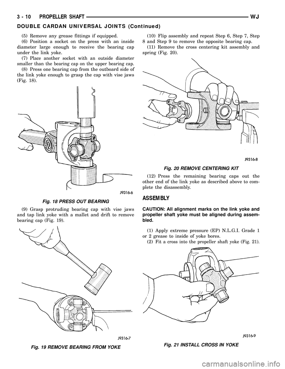
(8) Press one bearing cap from the outboard side of
the link yoke enough to grasp the cap with vise jaws
(Fig. 18).
(9) Grasp protruding bearing cap with vise jaws
and tap link yoke with a mallet and drift to remove
bearing cap (Fig. 19).(10) Flip assembly and repeat Step 6, Step 7, Step
8 and Step 9 to remove the opposite bearing cap.
(11) Remove the cross centering kit assembly and
spring (Fig. 20).
(12) Press the remaining bearing caps out the
other end of the link yoke as described above to com-
plete the disassembly.
ASSEMBLY
CAUTION: All alignment marks on the link yoke and
propeller shaft yoke must be aligned during assem-
bled.
(1) Apply extreme pressure (EP) N.L.G.I. Grade 1
or 2 grease to inside of yoke bores.
(2)
Fit a cross into the propeller shaft yoke (Fig. 21).
Fig. 18 PRESS OUT BEARING
Fig. 19 REMOVE BEARING FROM YOKE
Fig. 20 REMOVE CENTERING KIT
Fig. 21 INSTALL CROSS IN YOKE
3 - 10 PROPELLER SHAFTWJ
DOUBLE CARDAN UNIVERSAL JOINTS (Continued)
Page 56 of 2199
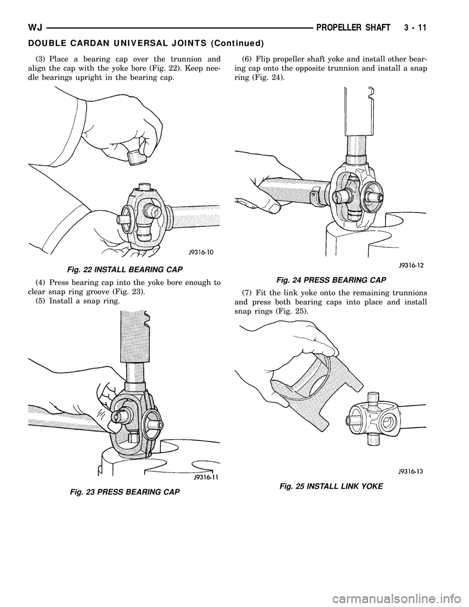
(3) Place a bearing cap over the trunnion and
align the cap with the yoke bore (Fig. 22). Keep nee-
dle bearings upright in the bearing cap.
(4) Press bearing cap into the yoke bore enough to
clear snap ring groove (Fig. 23).
(5) Install a snap ring.(6) Flip propeller shaft yoke and install other bear-
ing cap onto the opposite trunnion and install a snap
ring (Fig. 24).
(7) Fit the link yoke onto the remaining trunnions
and press both bearing caps into place and install
snap rings (Fig. 25).
Fig. 22 INSTALL BEARING CAP
Fig. 23 PRESS BEARING CAP
Fig. 24 PRESS BEARING CAP
Fig. 25 INSTALL LINK YOKE
WJPROPELLER SHAFT 3 - 11
DOUBLE CARDAN UNIVERSAL JOINTS (Continued)
Page 57 of 2199
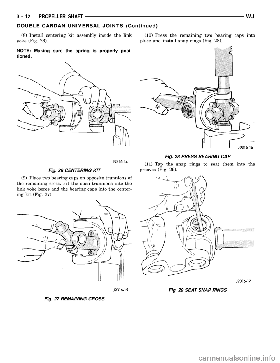
(8) Install centering kit assembly inside the link
yoke (Fig. 26).
NOTE: Making sure the spring is properly posi-
tioned.
(9) Place two bearing caps on opposite trunnions of
the remaining cross. Fit the open trunnions into the
link yoke bores and the bearing caps into the center-
ing kit (Fig. 27).(10) Press the remaining two bearing caps into
place and install snap rings (Fig. 28).
(11) Tap the snap rings to seat them into the
grooves (Fig. 29).
Fig. 26 CENTERING KIT
Fig. 27 REMAINING CROSS
Fig. 28 PRESS BEARING CAP
Fig. 29 SEAT SNAP RINGS
3 - 12 PROPELLER SHAFTWJ
DOUBLE CARDAN UNIVERSAL JOINTS (Continued)
Page 62 of 2199
BEARING NOISE
The axle shaft, differential and pinion bearings can
all produce noise when worn or damaged. Bearing
noise can be either a whining or a growling sound.
Pinion bearings have a constant-pitch noise. This
noise changes only with vehicle speed. Pinion bearing
noise will be higher pitched because it rotates at a
faster rate. Drive the vehicle and load the differen-
tial. If bearing noise occurs, the rear pinion bearing
is the source of the noise. If the bearing noise is
heard during a coast, the front pinion bearing is the
source.
Worn or damaged differential bearings usually pro-
duce a low pitch noise. Differential bearing noise is
similar to pinion bearing noise. The pitch of differen-
tial bearing noise is also constant and varies only
with vehicle speed.
Axle shaft bearings produce noise and vibration
when worn or damaged. The noise generally changes
when the bearings are loaded. Road test the vehicle.
Turn the vehicle sharply to the left and to the right.
This will load the bearings and change the noise
level. Where axle bearing damage is slight, the noise
is usually not noticeable at speeds above 30 mph.
LOW SPEED KNOCK
Low speed knock is generally caused by a worn
U-joint or by worn side-gear thrust washers. A worn
pinion shaft bore will also cause low speed knock.
VIBRATION
Vibration at the rear of the vehicle is usually
caused by a:
²Damaged drive shaft.
²Missing drive shaft balance weight(s).²Worn or out-of-balance wheels.
²Loose wheel lug nuts.
²Worn U-joint(s).
²Loose/broken springs.
²Damaged axle shaft bearing(s).
²Loose pinion gear nut.
²Excessive pinion yoke run out.
²Bent axle shaft(s).
Check for loose or damaged front±end components
or engine/transmission mounts. These components
can contribute to what appears to be a rear-end
vibration. Do not overlook engine accessories, brack-
ets and drive belts.
All driveline components should be examined
before starting any repair.
(Refer to 22 - TIRES/WHEELS - DIAGNOSIS AND
TESTING)
DRIVELINE SNAP
A snap or clunk noise when the vehicle is shifted
into gear (or the clutch engaged), can be caused by:
²High engine idle speed.
²Transmission shift operation.
²Loose engine/transmission/transfer case mounts.
²Worn U-joints.
²Loose spring mounts.
²Loose pinion gear nut and yoke.
²Excessive ring gear backlash.
²Excessive side gear to case clearance.
The source of a snap or a clunk noise can be deter-
mined with the assistance of a helper. Raise the vehi-
cle on a hoist with the wheels free to rotate. Instruct
the helper to shift the transmission into gear. Listen
for the noise, a mechanics stethoscope is helpful in
isolating the source of a noise.
WJFRONT AXLE - 186FBI 3 - 17
FRONT AXLE - 186FBI (Continued)
Page 64 of 2199
Condition Possible Causes Correction
Differential Gears Scored 1. Insufficient lubrication. 1. Replace scored gears. Fill
differential with the correct fluid type
and quantity.
2. Improper grade of lubricant. 2. Replace scored gears. Fill
differential with the correct fluid type
and quantity.
3. Excessive spinning of one
wheel/tire.3. Replace scored gears. Inspect all
gears, pinion bores, and shaft for
damage. Service as necessary.
Loss Of Lubricant 1. Lubricant level too high. 1. Drain lubricant to the correct
level.
2. Worn axle shaft seals. 2. Replace seals.
3. Cracked differential housing. 3. Repair as necessary.
4. Worn pinion seal. 4. Replace seal.
5. Worn/scored yoke. 5. Replace yoke and seal.
6. Axle cover not properly sealed. 6. Remove, clean, and re-seal
cover.
Axle Overheating 1. Lubricant level low. 1. Fill differential to correct level.
2. Improper grade of lubricant. 2. Fill differential with the correct
fluid type and quantity.
3. Bearing pre-loads too high. 3. Re-adjust bearing pre-loads.
4. Insufficient ring gear backlash. 4. Re-adjust ring gear backlash.
Gear Teeth Broke 1. Overloading. 1. Replace gears. Examine other
gears and bearings for possible
damage.
2. Erratic clutch operation. 2. Replace gears and examine the
remaining parts for damage. Avoid
erratic clutch operation.
3. Ice-spotted pavement. 3. Replace gears and examine
remaining parts for damage.
4. Improper adjustments. 4. Replace gears and examine
remaining parts for damage. Ensure
ring gear backlash is correct.
WJFRONT AXLE - 186FBI 3 - 19
FRONT AXLE - 186FBI (Continued)
Page 79 of 2199
AXLE SHAFTS
REMOVAL
If the axle shaft and hub bearing are being
removed in order to service another component, the
axle shaft and hub bearing can be removed as an
assembly.
(1) Raise and support the vehicle.
(2) Remove the wheel and tire assembly.
(3) Remove brake caliper, rotor and ABS wheel
speed sensor.
(4) Remove cotter pin, nut retainer and axle nut.
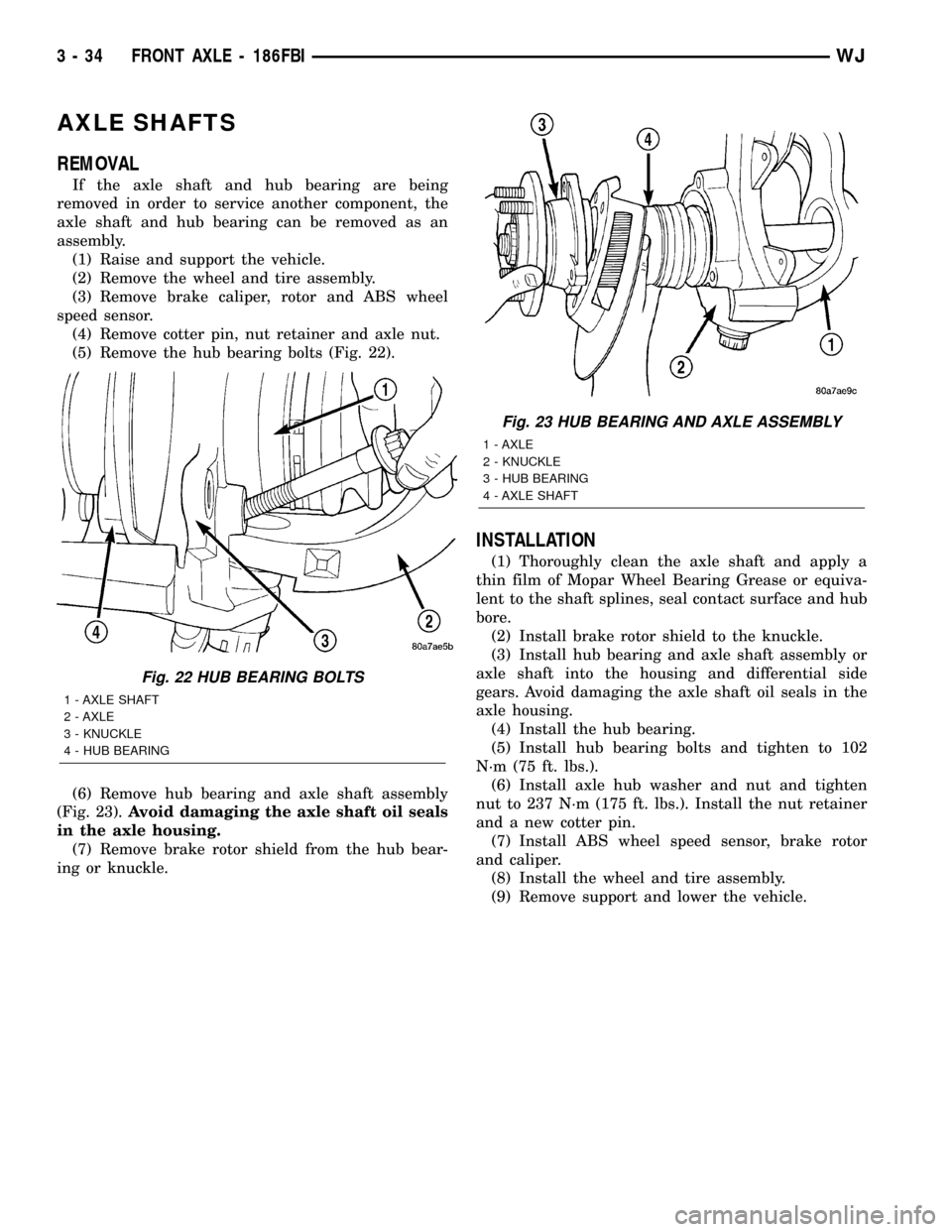
(5) Remove the hub bearing bolts (Fig. 22).
(6) Remove hub bearing and axle shaft assembly
(Fig. 23).Avoid damaging the axle shaft oil seals
in the axle housing.
(7) Remove brake rotor shield from the hub bear-
ing or knuckle.
INSTALLATION
(1) Thoroughly clean the axle shaft and apply a
thin film of Mopar Wheel Bearing Grease or equiva-
lent to the shaft splines, seal contact surface and hub
bore.
(2) Install brake rotor shield to the knuckle.
(3) Install hub bearing and axle shaft assembly or
axle shaft into the housing and differential side
gears. Avoid damaging the axle shaft oil seals in the
axle housing.
(4) Install the hub bearing.
(5) Install hub bearing bolts and tighten to 102
N´m (75 ft. lbs.).
(6) Install axle hub washer and nut and tighten
nut to 237 N´m (175 ft. lbs.). Install the nut retainer
and a new cotter pin.
(7) Install ABS wheel speed sensor, brake rotor
and caliper.
(8) Install the wheel and tire assembly.
(9) Remove support and lower the vehicle.
Fig. 22 HUB BEARING BOLTS
1 - AXLE SHAFT
2 - AXLE
3 - KNUCKLE
4 - HUB BEARING
Fig. 23 HUB BEARING AND AXLE ASSEMBLY
1 - AXLE
2 - KNUCKLE
3 - HUB BEARING
4 - AXLE SHAFT
3 - 34 FRONT AXLE - 186FBIWJ
Page 82 of 2199
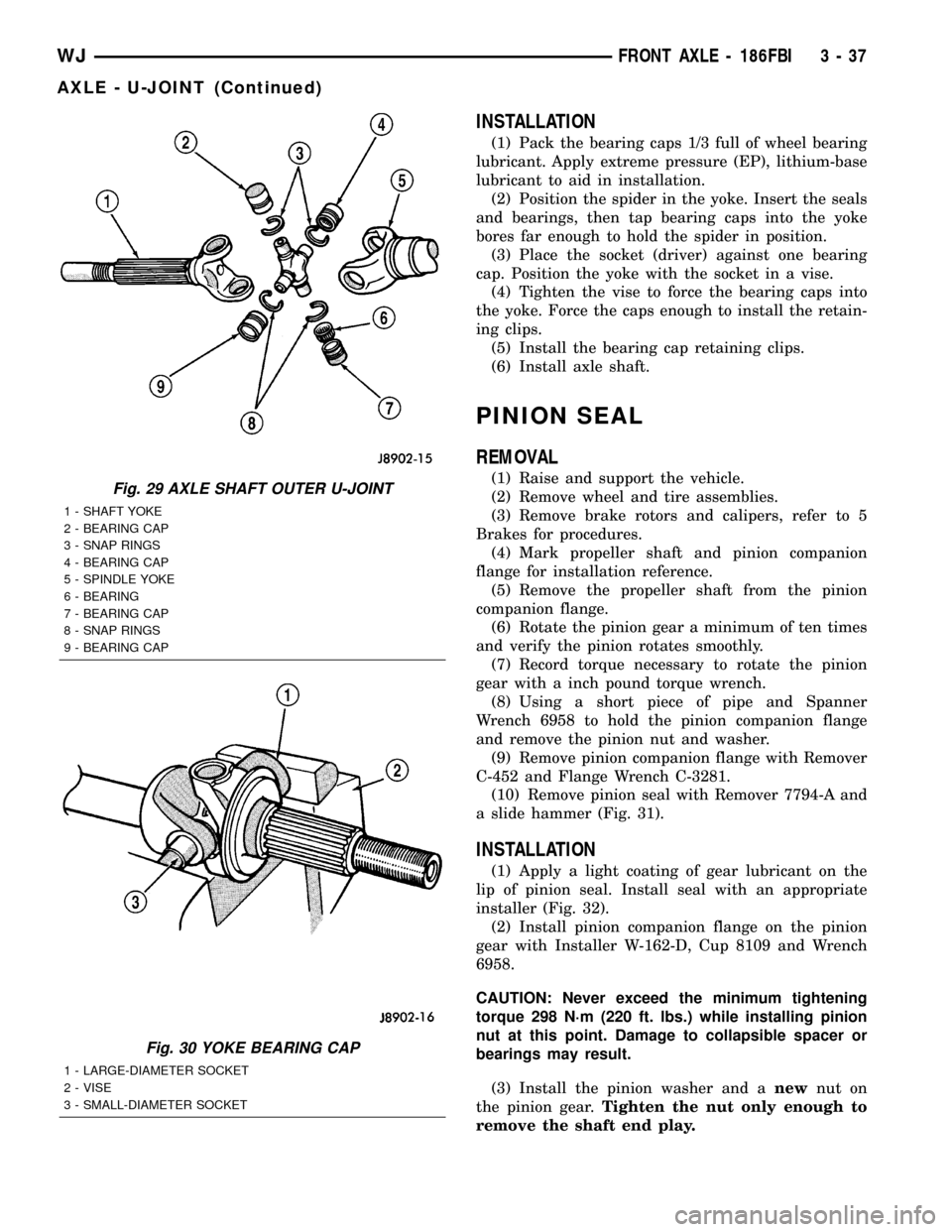
INSTALLATION
(1) Pack the bearing caps 1/3 full of wheel bearing
lubricant. Apply extreme pressure (EP), lithium-base
lubricant to aid in installation.
(2) Position the spider in the yoke. Insert the seals
and bearings, then tap bearing caps into the yoke
bores far enough to hold the spider in position.
(3) Place the socket (driver) against one bearing
cap. Position the yoke with the socket in a vise.
(4) Tighten the vise to force the bearing caps into
the yoke. Force the caps enough to install the retain-
ing clips.
(5) Install the bearing cap retaining clips.
(6) Install axle shaft.
PINION SEAL
REMOVAL
(1) Raise and support the vehicle.
(2) Remove wheel and tire assemblies.
(3) Remove brake rotors and calipers, refer to 5
Brakes for procedures.
(4) Mark propeller shaft and pinion companion
flange for installation reference.
(5) Remove the propeller shaft from the pinion
companion flange.
(6) Rotate the pinion gear a minimum of ten times
and verify the pinion rotates smoothly.
(7) Record torque necessary to rotate the pinion
gear with a inch pound torque wrench.
(8) Using a short piece of pipe and Spanner
Wrench 6958 to hold the pinion companion flange
and remove the pinion nut and washer.
(9) Remove pinion companion flange with Remover
C-452 and Flange Wrench C-3281.
(10) Remove pinion seal with Remover 7794-A and
a slide hammer (Fig. 31).
INSTALLATION
(1) Apply a light coating of gear lubricant on the
lip of pinion seal. Install seal with an appropriate
installer (Fig. 32).
(2) Install pinion companion flange on the pinion
gear with Installer W-162-D, Cup 8109 and Wrench
6958.
CAUTION: Never exceed the minimum tightening
torque 298 N´m (220 ft. lbs.) while installing pinion
nut at this point. Damage to collapsible spacer or
bearings may result.
(3) Install the pinion washer and anewnut on
the pinion gear.Tighten the nut only enough to
remove the shaft end play.
Fig. 29 AXLE SHAFT OUTER U-JOINT
1 - SHAFT YOKE
2 - BEARING CAP
3 - SNAP RINGS
4 - BEARING CAP
5 - SPINDLE YOKE
6 - BEARING
7 - BEARING CAP
8 - SNAP RINGS
9 - BEARING CAP
Fig. 30 YOKE BEARING CAP
1 - LARGE-DIAMETER SOCKET
2 - VISE
3 - SMALL-DIAMETER SOCKET
WJFRONT AXLE - 186FBI 3 - 37
AXLE - U-JOINT (Continued)
Page 97 of 2199
peak-noise range. If the noise stops or changes
greatly:
²Check for insufficient lubricant.
²Incorrect ring gear backlash.
²Gear damage.
Differential side gears and pinions can be checked
by turning the vehicle. They usually do not cause
noise during straight-ahead driving when the gears
are unloaded. The side gears are loaded during vehi-
cle turns. A worn pinion mate shaft can also cause a
snapping or a knocking noise.
BEARING NOISE
The axle shaft, differential and pinion bearings can
all produce noise when worn or damaged. Bearing
noise can be either a whining, or a growling sound.
Pinion bearings have a constant-pitch noise. This
noise changes only with vehicle speed. Pinion bearing
noise will be higher pitched because it rotates at a
faster rate. Drive the vehicle and load the differen-
tial. If bearing noise occurs, the rear pinion bearing
is the source of the noise. If the bearing noise is
heard during a coast, the front pinion bearing is the
source.
Worn or damaged differential bearings usually pro-
duce a low pitch noise. Differential bearing noise is
similar to pinion bearing noise. The pitch of differen-
tial bearing noise is also constant and varies only
with vehicle speed.
Axle shaft bearings produce noise and vibration
when worn or damaged. The noise generally changes
when the bearings are loaded. Road test the vehicle.
Turn the vehicle sharply to the left and to the right.
This will load the bearings and change the noise
level. Where axle bearing damage is slight, the noise
is usually not noticeable at speeds above 30 mph.
LOW SPEED KNOCK
Low speed knock is generally caused by a worn
U-joint or by worn side±gear thrust washers. A worn
pinion shaft bore will also cause low speed knock.
VIBRATION
Vibration at the rear of the vehicle is usually
caused by a:
²Damaged drive shaft.
²Missing drive shaft balance weight(s).
²Worn or out-of-balance wheels.
²Loose wheel lug nuts.
²Worn U-joint(s).
²Loose/broken springs.
²Damaged axle shaft bearing(s).
²Loose pinion gear nut.
²Excessive pinion yoke run out.
²Bent axle shaft(s).
Check for loose or damaged front-end components
or engine/transmission mounts. These components
can contribute to what appears to be a rearend vibra-
tion. Do not overlook engine accessories, brackets
and drive belts.
All driveline components should be examined
before starting any repair.
(Refer to 22 - TIRES/WHEELS - DIAGNOSIS AND
TESTING)
DRIVELINE SNAP
A snap or clunk noise when the vehicle is shifted
into gear (or the clutch engaged), can be caused by:
²High engine idle speed.
²Transmission shift operation.
²Loose engine/transmission/transfer case mounts.
²Worn U-joints.
²Loose spring mounts.
²Loose pinion gear nut and yoke.
²Excessive ring gear backlash.
²Excessive side gear to case clearance.
The source of a snap or a clunk noise can be deter-
mined with the assistance of a helper. Raise the vehi-
cle on a hoist with the wheels free to rotate. Instruct
the helper to shift the transmission into gear. Listen
for the noise, a mechanics stethoscope is helpful in
isolating the source of a noise.
3 - 52 REAR AXLE - 198RBIWJ
REAR AXLE - 198RBI (Continued)