crankshaft sensor replacement JEEP GRAND CHEROKEE 2003 WJ / 2.G Workshop Manual
[x] Cancel search | Manufacturer: JEEP, Model Year: 2003, Model line: GRAND CHEROKEE, Model: JEEP GRAND CHEROKEE 2003 WJ / 2.GPages: 2199, PDF Size: 76.01 MB
Page 328 of 2199

(3) Disconnect the instrument panel wire harness
connector from the SKIM connector.
(4) Remove the screw that secures the SKIM to
the bottom of the steering column housing (Fig. 16).
(5) Disengage the antenna ring of the SKIM from
around the ignition lock cylinder housing.
(6) Remove the SKIM from the steering column.
INSTALLATION
WARNING: ON VEHICLES EQUIPPED WITH AIR-
BAGS, DISABLE THE AIRBAG SYSTEM BEFORE
ATTEMPTING ANY STEERING WHEEL, STEERING
COLUMN, OR INSTRUMENT PANEL COMPONENT
DIAGNOSIS OR SERVICE. DISCONNECT AND ISO-
LATE THE BATTERY NEGATIVE (GROUND) CABLE,
THEN WAIT TWO MINUTES FOR THE AIRBAG SYS-
TEM CAPACITOR TO DISCHARGE BEFORE PER-
FORMING FURTHER DIAGNOSIS OR SERVICE. THIS
IS THE ONLY SURE WAY TO DISABLE THE AIRBAG
SYSTEM. FAILURE TO TAKE THE PROPER PRE-
CAUTIONS COULD RESULT IN ACCIDENTAL AIR-
BAG DEPLOYMENT AND POSSIBLE PERSONAL
INJURY.
(1) Position the SKIM to the underside of the
steering column (Fig. 16).
(2) Engage the antenna ring of the SKIM around
the ignition lock cylinder housing.
(3) Install and tighten the screw that secures the
SKIM to the bottom of the steering column hous-
ing.Tighten the screw to 3.4 N´m (30 in lbs.).
(4) Reconnect the instrument panel wire harness
connector to the SKIM connector.(5) Reinstall the steering column opening cover
onto the instrument panel. (Refer to 23 - BODY/IN-
STRUMENT PANEL/STEERING COLUMN OPEN-
ING COVER - INSTALLATION).
(6) Reconnect the battery negative cable.
(7) Perform the SKIS Replacement procedure
using the DRBIIIt.
(8) Perform the SKIS Initialization Procedure
using the DRBIIIt.
TRANSMISSION CONTROL
MODULE
DESCRIPTION
The Transmission Control Module (TCM) is located
in the engine compartment on the right (passenger)
side and is mounted to the inner fender (Fig. 17).
OPERATION
The Transmission Control Module (TCM) controls
all electronic operations of the transmission. The
TCM receives information regarding vehicle opera-
tion from both direct and indirect inputs, and selects
the operational mode of the transmission. Direct
inputs are hardwired to, and used specifically by the
TCM. Indirect inputs originate from other compo-
nents/modules, and are shared with the TCM via the
vehicle communication bus.
Some examples ofdirect inputsto the TCM are:
²Battery (B+) voltage
²Ignition ªONº voltage
²Transmission Control Relay (Switched B+)
²Throttle Position Sensor
²Crankshaft Position Sensor
²Transmission Range Sensor
Fig. 16
Fig. 17 Transmission Control Module Location
1 - TRANSMISSION CONTROL MODULE (TCM)
2 - 60±WAY CONNECTOR
WJELECTRONIC CONTROL MODULES 8E - 19
SENTRY KEY IMMOBILIZER MODULE (Continued)
Page 399 of 2199

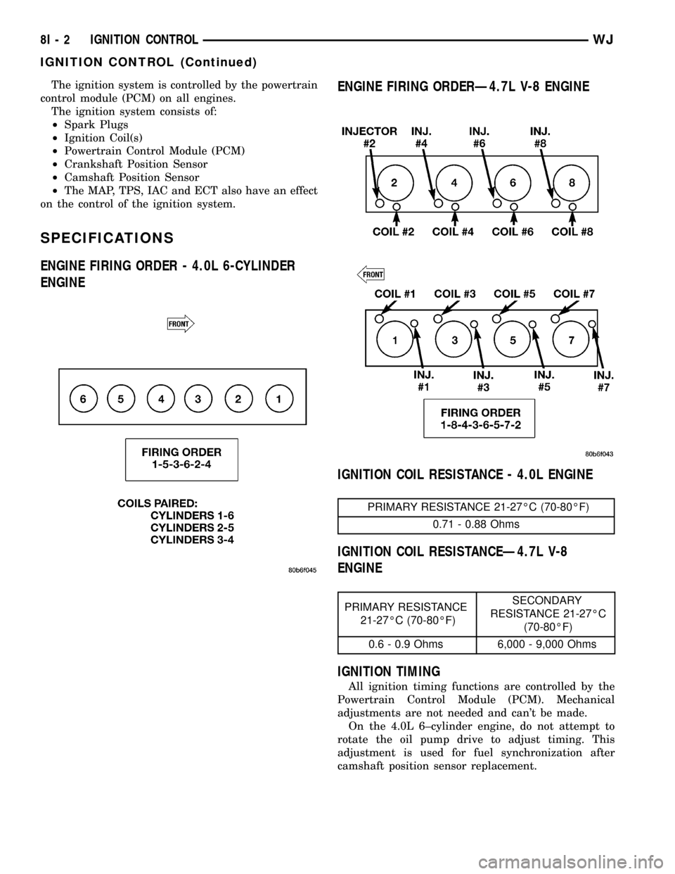
The ignition system is controlled by the powertrain
control module (PCM) on all engines.
The ignition system consists of:
²Spark Plugs
²Ignition Coil(s)
²Powertrain Control Module (PCM)
²Crankshaft Position Sensor
²Camshaft Position Sensor
²The MAP, TPS, IAC and ECT also have an effect
on the control of the ignition system.
SPECIFICATIONS
ENGINE FIRING ORDER - 4.0L 6-CYLINDER
ENGINEENGINE FIRING ORDERÐ4.7L V-8 ENGINE
IGNITION COIL RESISTANCE - 4.0L ENGINE
PRIMARY RESISTANCE 21-27ÉC (70-80ÉF)
0.71 - 0.88 Ohms
IGNITION COIL RESISTANCEÐ4.7L V-8
ENGINE
PRIMARY RESISTANCE
21-27ÉC (70-80ÉF)SECONDARY
RESISTANCE 21-27ÉC
(70-80ÉF)
0.6 - 0.9 Ohms 6,000 - 9,000 Ohms
IGNITION TIMING
All ignition timing functions are controlled by the
Powertrain Control Module (PCM). Mechanical
adjustments are not needed and can't be made.
On the 4.0L 6±cylinder engine, do not attempt to
rotate the oil pump drive to adjust timing. This
adjustment is used for fuel synchronization after
camshaft position sensor replacement.
8I - 2 IGNITION CONTROLWJ
IGNITION CONTROL (Continued)
Page 1392 of 2199

INSPECTION
Inspect the following components:
²Sprockets for excessive tooth wear. Some tooth
markings are normal and not a cause for sprocket
replacement.
²Idler sprocket assembly bushing and shaft for
excessive wear.
²Idler sprocket assembly spline joint. The joint
should be tight with no backlash or axial movement.
²Chain guides and tensioner arms. Replace these
parts if grooving in plastic face is more than 1 mm
(0.039 in.) deep. If plastic face is severely grooved or
melted, the tensioner lube jet may be clogged. The
tensioner should be replaced.
²secondary chain tensioner piston and ratcheting
device. Inspect for evidence of heavy contact between
tensioner piston and tensioner arm. If this condition
exist the tensioner and tensioner arm should be
replaced.
²Primary chain tensioner plastic faces. Replace as
required (Fig. 127).
INSTALLATION
(1) Using a vise, lightly compress the secondary
chain tensioner piston until the piston step is flush
with the tensioner body. Using a pin or suitable tool,
release ratchet pawl by pulling pawl back against
spring force through access hole on side of tensioner.
While continuing to hold pawl back, Push ratchet
device to approximately 2 mm from the tensioner
Fig. 124 Camshaft Position SensorÐRemoval
1 - CRANKSHAFT POSITION SENSOR
2 - CYLINDER HEAD COVER
3 - CAMSHAFT POSITION SENSOR
4 - RIGHT SIDE CYLINDER BLOCK
Fig. 125 Camshaft RotationÐLeft Side
1 - CAMSHAFT SPROCKET AND CHAIN
2 - ADJUSTABLE PLIERS
3 - CAMSHAFT
Fig. 126 Camshaft RotationÐRight Side
1 - ADJUSTABLE PLIERS
2 - CAMSHAFT DOWEL
WJENGINE - 4.7L 9 - 149
TIMING BELT/CHAIN AND SPROCKETS (Continued)
Page 1461 of 2199

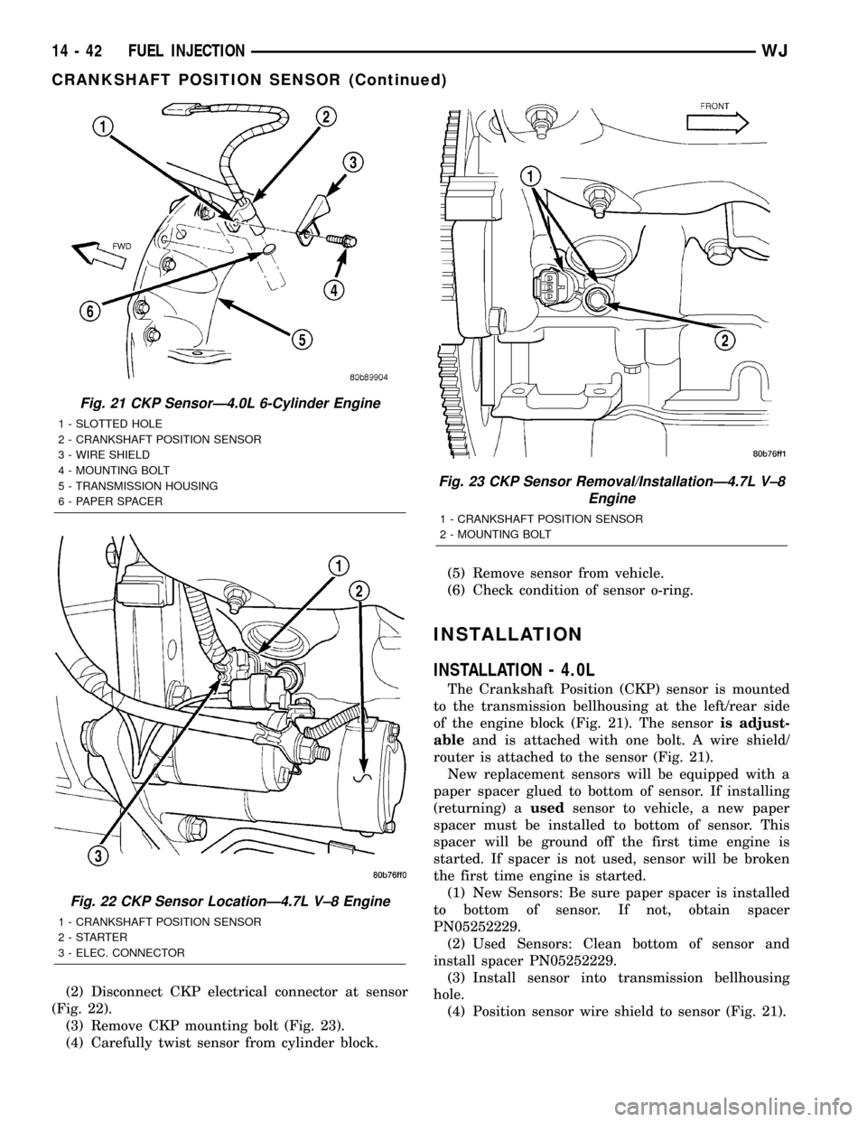
(2) Disconnect CKP electrical connector at sensor
(Fig. 22).
(3) Remove CKP mounting bolt (Fig. 23).
(4) Carefully twist sensor from cylinder block.(5) Remove sensor from vehicle.
(6) Check condition of sensor o-ring.
INSTALLATION
INSTALLATION - 4.0L
The Crankshaft Position (CKP) sensor is mounted
to the transmission bellhousing at the left/rear side
of the engine block (Fig. 21). The sensoris adjust-
ableand is attached with one bolt. A wire shield/
router is attached to the sensor (Fig. 21).
New replacement sensors will be equipped with a
paper spacer glued to bottom of sensor. If installing
(returning) ausedsensor to vehicle, a new paper
spacer must be installed to bottom of sensor. This
spacer will be ground off the first time engine is
started. If spacer is not used, sensor will be broken
the first time engine is started.
(1) New Sensors: Be sure paper spacer is installed
to bottom of sensor. If not, obtain spacer
PN05252229.
(2) Used Sensors: Clean bottom of sensor and
install spacer PN05252229.
(3) Install sensor into transmission bellhousing
hole.
(4) Position sensor wire shield to sensor (Fig. 21).
Fig. 21 CKP SensorÐ4.0L 6-Cylinder Engine
1 - SLOTTED HOLE
2 - CRANKSHAFT POSITION SENSOR
3 - WIRE SHIELD
4 - MOUNTING BOLT
5 - TRANSMISSION HOUSING
6 - PAPER SPACER
Fig. 22 CKP Sensor LocationÐ4.7L V±8 Engine
1 - CRANKSHAFT POSITION SENSOR
2-STARTER
3 - ELEC. CONNECTOR
Fig. 23 CKP Sensor Removal/InstallationÐ4.7L V±8
Engine
1 - CRANKSHAFT POSITION SENSOR
2 - MOUNTING BOLT
14 - 42 FUEL INJECTIONWJ
CRANKSHAFT POSITION SENSOR (Continued)