evap schematic JEEP GRAND CHEROKEE 2003 WJ / 2.G Workshop Manual
[x] Cancel search | Manufacturer: JEEP, Model Year: 2003, Model line: GRAND CHEROKEE, Model: JEEP GRAND CHEROKEE 2003 WJ / 2.GPages: 2199, PDF Size: 76.01 MB
Page 9 of 2199
VEHICLE EMISSION CONTROL
INFORMATION (VECI)
DESCRIPTION
All vehicles are equipped with a combined vehicle
emission control information (VECI) label(s). The
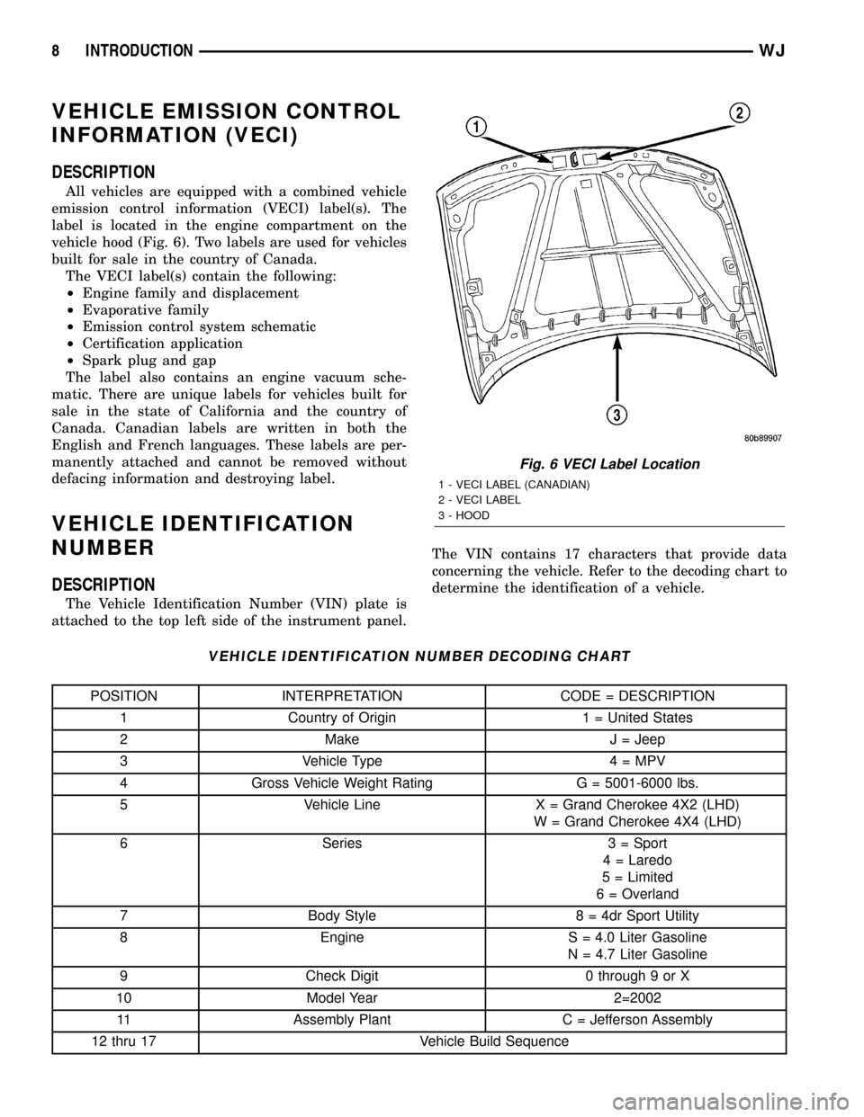
label is located in the engine compartment on the
vehicle hood (Fig. 6). Two labels are used for vehicles
built for sale in the country of Canada.
The VECI label(s) contain the following:
²Engine family and displacement
²Evaporative family
²Emission control system schematic
²Certification application
²Spark plug and gap
The label also contains an engine vacuum sche-
matic. There are unique labels for vehicles built for
sale in the state of California and the country of
Canada. Canadian labels are written in both the
English and French languages. These labels are per-
manently attached and cannot be removed without
defacing information and destroying label.
VEHICLE IDENTIFICATION
NUMBER
DESCRIPTION
The Vehicle Identification Number (VIN) plate is
attached to the top left side of the instrument panel.The VIN contains 17 characters that provide data
concerning the vehicle. Refer to the decoding chart to
determine the identification of a vehicle.
VEHICLE IDENTIFICATION NUMBER DECODING CHART
POSITION INTERPRETATION CODE = DESCRIPTION
1 Country of Origin 1 = United States
2 Make J = Jeep
3 Vehicle Type 4 = MPV
4 Gross Vehicle Weight Rating G = 5001-6000 lbs.
5 Vehicle Line X = Grand Cherokee 4X2 (LHD)
W = Grand Cherokee 4X4 (LHD)
6 Series 3 = Sport
4 = Laredo
5 = Limited
6 = Overland
7 Body Style 8 = 4dr Sport Utility
8 Engine S = 4.0 Liter Gasoline
N = 4.7 Liter Gasoline
9 Check Digit 0 through 9 or X
10 Model Year 2=2002
11 Assembly Plant C = Jefferson Assembly
12 thru 17 Vehicle Build Sequence
Fig. 6 VECI Label Location
1 - VECI LABEL (CANADIAN)
2 - VECI LABEL
3 - HOOD
8 INTRODUCTIONWJ
Page 2194 of 2199

REMOVAL - PCV VALVE - 4.7L
The PCV valve is located on the oil filler tube (Fig.
23). Two locating tabs are located on the side of the
valve (Fig. 23). These 2 tabs fit into a cam lock in the
oil filler tube. An o-ring seals the valve to the filler
tube.
(1) Disconnect PCV line/hose (Fig. 23) by discon-
necting rubber hose at PCV valve fitting.
(2) Remove PCV valve at oil filler tube by rotating
PCV valve downward (counter-clockwise) until locat-
ing tabs have been freed at cam lock (Fig. 23). After
tabs have cleared, pull valve straight out from filler
tube.To prevent damage to PCV valve locating
tabs, valve must be pointed downward for
removal. Do not force valve from oil filler tube.
(3) After valve is removed, check condition of valve
o-ring (Fig. 23).
INSTALLATION - PCV VALVE - 4.7L
The PCV valve is located on the oil filler tube (Fig.
23). Two locating tabs are located on the side of the
valve (Fig. 23). These 2 tabs fit into a cam lock in the
oil filler tube. An o-ring seals the valve to the filler
tube.
(1) Return PCV valve back to oil filler tube by
placing valve locating tabs (Fig. 23) into cam lock.
Press PCV valve in and rotate valve upward. A slight
click will be felt when tabs have engaged cam lock.
Valve should be pointed towards rear of vehicle.
(2) Connect PCV line/hose and rubber hose to PCV
valve.
VACUUM LINES
DESCRIPTION
A vacuum schematic for emission related items can
be found on the VECI label. Refer to Vehicle Emis-
sion Control Information (VECI) Label for label loca-
tion.
VAPOR CANISTER
DESCRIPTION
A maintenance free, EVAP canister is used on all
gasoline powered models. The canister is attached to
a two-piece support bracket located behind the left-
rear wheel.
OPERATION
The EVAP canister is filled with granules of an
activated carbon mixture. Fuel vapors entering the
EVAP canister are absorbed by the charcoal granules.
The canister serves two functions: as a temporary
fuel vapor storage point while refueling the vehicle
for the ORVR system, as a temporary vapor storage
point while the engine is running.
Fuel tank pressure vents into the EVAP canister.
Fuel vapors are temporarily held in the canister until
they can be drawn into the intake manifold. The duty
cycle EVAP canister purge solenoid allows the EVAP
canister to be purged at predetermined times and at
certain engine operating conditions.
Refer to ORVR for additional information.
Fig. 23 PCV Valve/Oil Filler Tube Location
1 - O-RING
2 - LOCATING TABS
3 - CAM LOCK
4 - OIL FILLER TUBE
5 - PCV LINE/HOSE
6 - P C V VA LV E
WJEVAPORATIVE EMISSIONS 25 - 39
PCV VALVE (Continued)