liftgate ajar switch JEEP GRAND CHEROKEE 2003 WJ / 2.G Workshop Manual
[x] Cancel search | Manufacturer: JEEP, Model Year: 2003, Model line: GRAND CHEROKEE, Model: JEEP GRAND CHEROKEE 2003 WJ / 2.GPages: 2199, PDF Size: 76.01 MB
Page 313 of 2199
BCM programming then performs those tasks and
provides features through both PCI data bus commu-
nication with other electronic modules and hard
wired outputs to a number of relays. These relays
provide the BCM with the ability to control numer-
ous high current accessory systems in the vehicle.
The BCM circuitry operates on battery current
received through fuses in the Junction Block (JB) on a
non-switched fused B(+) circuit, a fused ignition switch
output (start-run) circuit, and a fused ignition switch
output (run-accessory) circuit. This arrangement allows
the BCM to provide some features regardless of the
ignition switch position. The BCM circuitry is grounded
through the chassis beneath the center console.
The BCM monitors its own internal circuitry as
well as many of its input and output circuits, and
will store a Diagnostic Trouble Code (DTC) in elec-
tronic memory for any failure it detects. These DTCs
can be retrieved and diagnosed using a DRBIIItscan
tool. Refer to the appropriate diagnostic information.
HARD WIRED INPUTS
The hard wired inputs to the BCM include the fol-
lowing:
²A/C switch signal
²Ambient temperature sensor signal
²Body control module flash enable
²Coolant level switch sense
²Door ajar switch sense (two circuits - one left
rear, and one right rear)
²Driver seat heater switch mux
²Fog lamp switch sense
²Fused B(+)
²Fused ignition switch output (run-acc)
²Fused ignition switch output (st-run)
²Ground (five circuits - two Z1, and three Z2)
²Hazard switch sense
²Headlamp switch mux
²High beam switch sense
²Hood ajar switch sense (export)
²Key-in ignition switch sense
²Liftgate ajar switch sense
²Liftgate courtesy disable
²Liftgate flip-up ajar switch sense
²Panel lamps dimmer signal
²Park lamp relay output
²Passenger seat heater switch mux
²PCI bus
²Radio control mux
²Rear window defogger switch sense
²Seat belt switch sense
²Ultralight sensor signal
²Washer fluid switch sense
²Washer pump switch sense
²Windshield wiper switch mux
²Wiper park switch sense
MESSAGING
The BCM uses the following messages received
from other electronic modules over the PCI data bus:
²Accessory Delay Control (DDM/PDM)
²Battery Temperature (PCM)
²Chime Request (EMIC, EVIC, SKIM)
²Cylinder Lock Switch Status (DDM)
²Door Ajar Status/Front Doors (DDM/PDM)
²Door Lock Status (DDM/PDM)
²Engine Model (PCM)
²Engine RPM (PCM)
²Engine Temperature (PCM)
²English/Metric Default (EMIC)
²Fuel Tank Level (PCM)
²Fuel Used/Injector Pulses (PCM)
²Panic Control (PDM)
²Programmable Features Preferences/Audible &
Optical Chirps/Headlamp Delay (EVIC)
²RKE Status (PDM)
²Vehicle Identification Number (PCM)
²Vehicle Speed (PCM)
The BCM provides the following messages to other
electronic modules over the PCI data bus:
²A/C Switch Status (PCM)
²Ambient Temperature Data (AZC/EVIC/PCM)
²Average/Instantaneous Fuel Economy (EVIC)
²Country Code (EMIC)
²Courtesy Lamp Status (DDM/PDM)
²Distance To Empty (EVIC)
²Elapsed Ignition On Timer (EVIC)
²English/Metric Status (EMIC)
²Front & Rear Door Ajar Status (EVIC)
²Front & Rear Fog Lamp Status (EMIC)
²Heated Seat Switch Status (HSM/MHSM)
²High Beam Status (EMIC)
²Ignition Off Timer (EVIC)
²Ignition Switch Position (DDM/PDM)
²Key-In Ignition Status (DDM/PDM)
²Low Beam Status (EMIC)
²Panel Lamp Status (AZC/EMIC/Radio)
²Rear Window Defogger Relay Status (DDM/
PDM)
²Remote Radio Switch Status (Radio)
²Seatbelt Status (EMIC/MHSM/MSM)
DIAGNOSIS AND TESTING - BODY CONTROL
MODULE
The hard wired inputs to and outputs from the
Body Control Module (BCM) may be diagnosed and
tested using conventional diagnostic tools and proce-
dures. Refer to the appropriate wiring information.
Conventional diagnostic methods may not prove
conclusive in the diagnosis of the BCM. In order to
obtain conclusive testing of the BCM, the Program-
mable Communications Interface (PCI) data bus net-
work and all of the electronic modules that provide
8E - 4 ELECTRONIC CONTROL MODULESWJ
BODY CONTROL MODULE (Continued)
Page 317 of 2199
Frequency (RF) Remote Keyless Entry (RKE)
receiver. The DDM and PDM control and integrate
many functions and features of the vehicle through
both hard wired outputs and messages over the PCI
data bus. The functions and features that the door
modules support or control include the following:
²Automatic Door Lock- The two door modules
provide an automatic door lock feature which locks
the doors when the vehicle is moving. This is a pro-
grammable feature.
²Automatic Door Unlock On Exit- The two
door modules provide an automatic door unlock on
exit feature. This feature will unlock all the doors if
they were locked via the automatic door lock feature
after the vehicle has stopped moving and the driver
door is opened. This is a programmable feature via
the EVIC.
²Customer Programmable Features- Each
door module provides support for certain customer
programmable features that are monitored on the
PCI bus.
²Cylinder Lock Switch Status- The DDM
monitors and transmits the status of the cylinder
lock switch on the driver side front door lock cylin-
der.
²Door Courtesy Lamp Control- Each door
module provides control of its own optional front
door-mounted courtesy lamp.
²Door Lock Inhibit- Each door module pro-
vides a door lock inhibit feature which prevents the
doors from being locked with a power lock switch ifthe key was left in the ignition and a front door is
open.
²Express-Down Window- The DDM provides
an express-down feature for the driver side front door
window only.
²Extended Window Operation- Both door
modules provide an extended power window opera-
tion feature that allows operation of the power win-
dows for 45 seconds following ignition Off or until a
front door is opened.
²Front Door Ajar Switch Status- Each door
module monitors and transmits the status of its own
front door ajar switch.
²Heated Mirrors- Each door module provides
control for its own optional heated outside rear view
mirror.
²Illuminated Entry- Each door module sup-
ports an illuminated entry feature through its own
optional front door-mounted courtesy lamp.
²Memory Mirrors- Each door module provides
control for its own optional memory outside rear view
mirror.
²Memory Switch- The DDM monitors the sta-
tus of the optional memory switch and controls the
illumination of the memory switch ªsetº Light Emit-
ting Diode (LED) indicator and illumination lamps.
²Memory System- The DDM transmits memory
set and recall messages based upon inputs from the
memory switch. If the optional RKE linked to mem-
ory feature is enabled, the DDM will also transmit
memory recall messages based upon memory
requests received from the Remote Keyless Entry
(RKE) system in the PDM. Certain memory system
features are programmable.
²Power Foldaway Mirrors - Export Only-
Each door module provides support for the optional
power foldaway outside mirrors. The DDM also
houses the control switch for this system.
²Power Lock Control- The DDM provides con-
trol for the driver side front door power lock motor,
while the PDM provides control for the power lock
motors of the three remaining doors and the liftgate.
²Power Lock Switch Status- Each door mod-
ule monitors and transmits the status of its own inte-
gral power lock switch.
²Power Window Control- Each door module
provides control for both the front and rear door
power window motors and the rear door power win-
dow switches on the same side of the vehicle.
²Power Window Switch Status- The DDM
monitors and transmits the status of its integral pas-
senger side front and rear power window switches.
²Remote Keyless Entry- The PDM monitors
and transmits the status of the Remote Keyless
Entry (RKE) system and provides support for the
RKE Lock (with the optional horn chirp and park
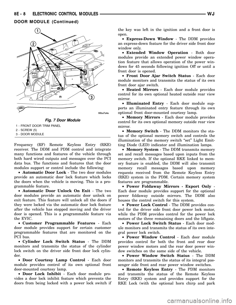
Fig. 7 Door Module
1 - FRONT DOOR TRIM PANEL
2 - SCREW (5)
3 - DOOR MODULE
8E - 8 ELECTRONIC CONTROL MODULESWJ
DOOR MODULE (Continued)
Page 318 of 2199
lamp flash features), Unlock with the optional RKE
unlock, and Panic Mode functions. The optional RKE
features are programmable.
²Switch Illumination- Each door module pro-
vides control of the power window and power lock
switch illumination for the front and rear doors on
the same side of the vehicle. The DDM provides con-
trol of the power mirror switch illumination.
²Window Lockout- The DDM monitors and
transmits the status of its integral window lockout
switch to provide the power window lockout feature
and coordinate power window switch knob illumina-
tion.
The door modules are serviced only as complete
units. Many of the features in the vehicle controlled
or supported by the door modules are programmable
using either the Electronic Vehicle Information Cen-
ter (EVIC) user interface, or the DRBIIItscan tool. If
a door module is damaged or faulty, the entire door
module unit must be replaced.
OPERATION
The microprocessor-based DDM and PDM hard-
ware and software monitors integral and hard wired
external switch inputs as well as those resources it
shares with other electronic modules in the vehicle
through its communication over the PCI data bus
network. The internal programming and all of these
inputs allow the DDM or PDM microprocessor to
determine the tasks it needs to perform and their
priorities, as well as both the standard and optional
features that it should provide.
The DDM and PDM are powered by a fused bat-
tery circuit so that they can operate regardless of the
ignition switch position. The DDM and PDM cir-
cuitry is grounded to the chassis beneath the front
seat.
The DDM and PDM can be diagnosed using a
DRBIIItscan tool. Refer to the appropriate diagnos-
tic information.
HARD WIRED INPUTS
The hard wired inputs to the door modules include
the following:
²Door ajar switch sense
²Driver door key cylinder switch sense (DDM)
²Fused B(+)
²Ground
²Memory switch mux (DDM)
²Mirror horizontal position signal
²Mirror vertical position signal
²PCI bus
HARD WIRED OUTPUTS
The hard wired outputs of the door modules
include the following:
²Courtesy lamp driver
²Courtesy lamp ground
²Diagnostic out (DDM)
²Door/liftgate lock driver
²Door/liftgate unlock driver
²Door switch illumination (rear power window)
²Front window driver (down)
²Front window driver (up)
²Memory set indicator driver (DDM)
²Memory switch return (DDM)
²Mirror common driver
²Mirror heater ground
²Mirror heater 12V supply
²Rear window driver (down)
²Rear window driver (up)
²Mirror horizontal driver
²Mirror sensor ground
²Mirror vertical driver
²PCI bus
²Switch illumination driver (memory - DDM)
MESSAGING
The door modules use the following messages
received from other electronic modules over the PCI
data bus:
²Accessory Delay Control (PDM)
²Courtesy Lamp Status (BCM)
²Door Ajar Status/Rear Doors (BCM)
²Door Lock Status (DDM/PDM)
²Ignition Switch Position (BCM)
²Key-In Ignition Status (BCM)
²Programmable Features Preferences/Auto Lock/
Auto Unlock/RKE Unlock Sequence/RKE Link to
Memory (EVIC)
²Memory Recall (DDM)
²Rear Window Defogger Relay Status (BCM)
²Vehicle Speed (PCM)
The door modules provide the following messages
to other electronic modules over the PCI data bus:
²Cylinder Lock Switch Status (BCM)
²Door Ajar Status/Front Doors (BCM/DDM/PDM)
²Door Lock Status (DDM/PDM)
²Memory Recall (PDM/MHSM/MSM/Radio)
²Memory Set Switch Status (PDM/MHSM/MSM/
Radio)
²Panic Control (BCM)
²Power Window Switch Status (PDM)
²RKE Status (BCM/DDM)
²Window Lockout Switch Status (PDM)
WJELECTRONIC CONTROL MODULES 8E - 9
DOOR MODULE (Continued)
Page 479 of 2199
LAMPS/LIGHTING - INTERIOR
TABLE OF CONTENTS
page page
LAMPS/LIGHTING - INTERIOR
SPECIFICATIONS
...................................28
COURTESY LAMP
REMOVAL
REMOVAL - BULB.....................29
REMOVAL - LAMP.....................29
INSTALLATION
INSTALLATION - BULB.................29
INSTALLATION - LAMP.................29
DOME LAMP
REMOVAL
REMOVAL - BULB.....................29
REMOVAL - LAMP.....................29
INSTALLATION
INSTALLATION - BULB.................29
INSTALLATION - LAMP.................29
DOOR AJAR SWITCH
DESCRIPTION
DESCRIPTION - DOOR AJAR SWITCH.....29
DESCRIPTION - FLIP UP GLASS AJAR
SWITCH............................29DESCRIPTION - LIFTGATE AJAR SWITCH . . 30
OPERATION
OPERATION - DOOR AJAR SWITCH.......30
OPERATION - FLIP UP GLASS AJAR
SWITCH............................30
OPERATION - LIFTGATE AJAR SWITCH....30
DIAGNOSIS AND TESTING - DOOR AJAR
SWITCH............................30
GLOVE BOX LAMP/SWITCH
REMOVAL.............................31
INSTALLATION.........................31
READING LAMP
DESCRIPTION.........................32
OPERATION...........................32
REMOVAL.............................32
INSTALLATION.........................32
TRANS RANGE INDICATOR ILLUMINATION
DESCRIPTION.........................32
VANITY LAMP
REMOVAL.............................32
INSTALLATION.........................32
LAMPS/LIGHTING - INTERIOR
SPECIFICATIONS
CAUTION: Do not use bulbs other than the bulbs
listed in the Bulb Application Table. Damage to
lamp can result.
Service procedures for most of the lamps in the
instrument panel, are located in Electrical, Instru-
ment Panel. Some components have lamps that can
only be serviced by an Authorized Service Center
(ASC) after the component is removed from the vehi-
cle.
LAMP BULB TYPE
A/C HEATER NOT SERVICED
ASH RECEIVER 161
CLIMATE CONTROL 74
PASSENGER ASSIST
HANDLE214±2
FRONT READING 192
GLOVE COMPARTMENT 194
TELLTALE/HAZARD LAMP 74
HEATER NOT SERVICED
OVERHEAD CONSOLE 192
RADIO ASC
REAR CARGO 214±2
UNDER PANEL COURTESY 906
CLUSTER ILLUMINATION 103
SUNVISOR VANITY CHRYSLER P/N
6501966
8L - 28 LAMPS/LIGHTING - INTERIORWJ
Page 480 of 2199
COURTESY LAMP
REMOVAL
REMOVAL - BULB
(1) Remove the door trim panel. (Refer to 23 -
BODY/DOOR - FRONT/TRIM PANEL - REMOVAL)
for the service procedures.
(2) Remove the bulb socket from the lamp.
(3) Remove the bulb from the socket.
REMOVAL - LAMP
(1) Remove door trim panel. (Refer to 23 - BODY/
DOOR - FRONT/TRIM PANEL - REMOVAL) for the
procedures.
(2) Disengage the electrical connectors.
(3) Depress the locking tabs and remove the lamp
module.
(4) Remove the bulb socket.
INSTALLATION
INSTALLATION - BULB
(1) Install the bulb in the socket.
(2) Install the bulb socket in the lamp.
(3) Install the door trim panel.
INSTALLATION - LAMP
(1) Install the bulb socket into the lamp module.
(2) Align the lamp module with the door trim
panel.
(3) Snap the lamp module into place.
(4) Install the door panel.
DOME LAMP
REMOVAL
REMOVAL - BULB
(1) Rotate the the grab handle down.
(2) Remove the screws retaining the grab handle/
dome lens.
(3) Remove the grab handle/lens from the module.
(4) Remove the bulb from the lamp terminals.
REMOVAL - LAMP
It will be necessary to partially remove the head-
liner to remove the bulb socket.
(1) Remove the screws holding the grab handle/
lens assembly to the headliner and roof panel.(2) Lower the headliner as needed. (Refer to 23 -
BODY/INTERIOR/HEADLINER - REMOVAL) for the
service procedure.
(3) Separate the lamp socket from the headliner
and roof panel.
(4) Disconnect the wire connector.
INSTALLATION
INSTALLATION - BULB
(1) Insert the bulb into the lamp terminals.
(2) Position the grab handle/lens on the lamp mod-
ule.
(3) Install the screws retaining the grab handle/
lens to the lamp module.
INSTALLATION - LAMP
(1) Position the lamp socket on the headliner and
roof panel.
(2) Connect the wire harness.
(3) Install the headliner.
(4) Position the grab handle/lens on the lamp mod-
ule.
(5) Install the screws retaining the grab handle/
lens into the lamp socket.
DOOR AJAR SWITCH
DESCRIPTION
DESCRIPTION - DOOR AJAR SWITCH
The door ajar switches are integral to the door
latch mechnicism. The front door ajar switches are
actuated by the front door latch mechanisms, and are
hard wired between a body ground and the Driver
Door Module (DDM) or the Passenger Door Module
(PDM). The rear door ajar switches are actuated by
the rear door latch mechanisms, and are hard wired
between a body ground and the Body Control Module
(BCM) through the rear door and body wire har-
nesses.
The door ajar switches cannot be adjusted or
repaired and, if faulty or damaged, the door latch
unit must be replaced. (Refer to 23 - BODY/DOOR -
FRONT/LATCH - REMOVAL) or (Refer to 23 -
BODY/DOORS - REAR/LATCH - REMOVAL) for the
service procedures. For complete circuit diagrams,
refer to the appropriate wiring information.
DESCRIPTION - FLIP UP GLASS AJAR SWITCH
The liftgate flip-up glass ajar switch is integral to
the liftgate flip-up glass latch mechnicism. The lift-
gate flip-up glass ajar switch is actuated by the lift-
gate flip-up glass latch mechanism, and is hard
WJLAMPS/LIGHTING - INTERIOR 8L - 29
Page 481 of 2199
wired between a body ground, the Body Control Mod-
ule (BCM) and the rear wiper motor module through
the liftgate and body wire harnesses.
The liftgate flip-up glass ajar switch cannot be
adjusted or repaired and, if faulty or damaged, the
liftgate flip-up glass latch unit must be replaced.
(Refer to 23 - BODY/DECKLID/HATCH/LIFTGATE/
TAILGATE/FLIP-UP GLASS LATCH - REMOVAL)
for the service procedures. For complete circuit dia-
grams, refer to the appropriate wiring information.
DESCRIPTION - LIFTGATE AJAR SWITCH
The two liftgate ajar switches are integral to the
two liftgate latch mechanisms. The two liftgate ajar
switches are actuated by the liftgate latch mecha-
nisms, and are hard wired with each other between a
body ground and the Body Control Module (BCM)
through the liftgate and body wire harnesses.
The liftgate ajar switches cannot be adjusted or
repaired and, if faulty or damaged, the liftgate latch
unit must be replaced. (Refer to 23 - BODY/DECK-
LID/HATCH/LIFTGATE/TAILGATE/LATCH -
REMOVAL) for the service procedures. For complete
circuit diagrams, refer to the appropriate wiring
information.
OPERATION
OPERATION - DOOR AJAR SWITCH
The front door ajar switches close a path to ground
for the DDM or the PDM when a front door is
opened, and opens the ground path when a front door
is closed. The rear door ajar switches close a path to
ground for the BCM when a rear door is opened, and
opens the ground path when a rear door is closed.
The DDM, PDM, or BCM read the switch status then
send the proper switch status messages to other
modules over the Programmable Communications
Interface (PCI) data bus network. The door ajar
switch status message is used by the BCM as an
input for Vehicle Theft Security System (VTSS) oper-
ation.
OPERATION - FLIP UP GLASS AJAR SWITCH
The liftgate flip-up glass ajar switch can close a
path to ground for the BCM and the rear wiper
motor module when the liftgate flip-up glass is
opened, and opens the ground path when the liftgate
flip-up glass is closed. The rear wiper motor module
uses the liftgate flip-up glass ajar switch input to
control the rear wiper operation, and will park the
rear wiper blade if this input indicates that the lift-
gate flip-up glass is ajar. The BCM reads the switch
status then sends the proper switch status message
to other modules over the Programmable Communi-cations Interface (PCI) data bus network. The liftgate
flip-up glass ajar switch status message is used by
the BCM as an input for Vehicle Theft Security Sys-
tem (VTSS) operation.
OPERATION - LIFTGATE AJAR SWITCH
Each of the liftgate ajar switches can close a path
to ground for the BCM when the liftgate is opened,
and opens the ground path when the liftgate is
closed. The BCM reads the switch status then sends
the proper switch status message to other modules
over the Programmable Communications Interface
(PCI) data bus network. The liftgate ajar switch sta-
tus message is used by the BCM as an input for
Vehicle Theft Security System (VTSS) operation.
DIAGNOSIS AND TESTING - DOOR AJAR
SWITCH
The following diagnosis and testing is only
for the chime functions. For interior lamp diag-
nosis, refer to the appropriate wiring informa-
tion.The driver door ajar switch is hard wired to the
Driver Door Module (DDM). The DDM communicates
the switch status to the other modules in the vehicle
on the Programmable Communications Interface
(PCI) data bus network. The following test will diag-
nose a faulty driver door ajar switch and circuits. For
complete circuit diagrams, refer to the appropriate
wiring information.
WARNING: ON VEHICLES EQUIPPED WITH AIR-
BAGS, REFER TO ELECTRICAL, RESTRAINTS
BEFORE ATTEMPTING ANY STEERING WHEEL,
STEERING COLUMN, OR INSTRUMENT PANEL
COMPONENT DIAGNOSIS OR SERVICE. FAILURE
TO TAKE THE PROPER PRECAUTIONS COULD
RESULT IN ACCIDENTAL AIRBAG DEPLOYMENT
AND POSSIBLE PERSONAL INJURY.
(1) Check that the interior lighting switch on the
control stalk of the left multi-function switch is not
in the dome lamp disable position. Open the driver
side front door and note whether the interior lamps
light. They should light. If OK, refer to Key-In Igni-
tion Switch in the Diagnosis and Testing section of
this group for further diagnosis of the chime warning
system. If not OK, go to Step 2.
(2) Disconnect and isolate the battery negative
cable. Remove the trim panel from the driver front
door and disconnect the 4-way door wire harness con-
nector from the front door latch connector. Check for
continuity between the ground circuit of the 4-way
door wire harness connector and a good ground.
There should be continuity. If OK, go to Step 3. If not
OK, repair the ground circuit.
8L - 30 LAMPS/LIGHTING - INTERIORWJ
DOOR AJAR SWITCH (Continued)
Page 501 of 2199
the engine compartment. This relay can be energized
by the BCM to sound the horns as an audible alert
for the RKE panic function and, if the Sound Horn
on Lock programmable feature is enabled, as an
audible verification for the RKE lock event. (Refer to
8 - ELECTRICAL/HORN/HORN RELAY - DESCRIP-
TION).
LOW BEAM HEADLAMP RELAY
The low beam headlamp relay is a electromechan-
ical device that switches battery current to the head-
lamp low beams when the BCM grounds the relay
coil. The low beam headlamp relay is located in the
junction block in the passenger compartment. This
relay can be energized by the BCM to flash the head-
lamp low beams as an optical alert for the RKE panic
function. (Refer to 8 - ELECTRICAL/LAMPS/LIGHT-
ING - EXTERIOR/HEADLAMP - DESCRIPTION).
DESCRIPTION - LIFTGATE FLIP-UP GLASS
POWER RELEASE SYSTEM
A power operated liftgate flip-up glass release sys-
tem is standard factory installed equipment on this
model. The liftgate flip-up glass power release system
allows the flip-up glass latch to be released electri-
cally by depressing a switch located on the bottom of
the liftgate license plate lamp housing unit, above
the license plate on the outside of the liftgate.
The liftgate flip-up glass release system operates
on non-switched battery current supplied through a
fuse in the junction block so that the system remains
functional, regardless of the ignition switch position.
However, a limit switch that is integral to the liftgate
latch actuator unit opens to prevent the flip-up glass
latch from being actuated when the liftgate latch is
locked.
The liftgate flip-up glass power release system
includes the following components:
²Liftgate Flip-Up Glass Limit Switch- The
liftgate flip-up glass limit switch is integral to the
liftgate latch unit. (Refer to 23 - BODY/DECKLID/
HATCH/LIFTGATE/TAILGATE/LATCH - REMOVAL)
and (Refer to 23 - BODY/DECKLID/HATCH/LIFT-
GATE/TAILGATE/LATCH - INSTALLATION).
²Liftgate Flip-Up Glass Release Motor- The
liftgate flip-up glass release motor is integral to the
liftgate flip-up glass latch unit. (Refer to 23 - BODY/
DECKLID/HATCH/LIFTGATE/TAILGATE/FLIP-UP
GLASS LATCH - REMOVAL) and (Refer to 23 -
BODY/DECKLID/HATCH/LIFTGATE/TAILGATE/
FLIP-UP GLASS LATCH - INSTALLATION).
²Liftgate Flip-Up Glass Release Switch- The
liftgate flip-up glass release switch is integral to the
liftgate license plate lamp housing. (Refer to 23 -
BODY/DECKLID/HATCH/LIFTGATE/TAILGATE/
FLIP-UP GLASS SWITCH - REMOVAL) and (Referto 23 - BODY/DECKLID/HATCH/LIFTGATE/TAIL-
GATE/FLIP-UP GLASS SWITCH - INSTALLATION).
Hard wired circuitry connects the liftgate flip-up
glass power release system components to the electri-
cal system of the vehicle. These hard wired circuits
are integral to several wire harnesses, which are
routed throughout the vehicle and retained by many
different methods. These circuits may be connected to
each other, to the vehicle electrical system and to the
liftgate flip-up glass power release system compo-
nents through the use of a combination of soldered
splices, splice block connectors, and many different
types of wire harness terminal connectors and insu-
lators. Refer to the appropriate wiring information.
The wiring information includes wiring diagrams,
proper wire and connector repair procedures, further
details on wire harness routing and retention, as well
as pin-out and location views for the various wire
harness connectors, splices and grounds.OPERATION
OPERATION - POWER LOCK SYSTEM
The Passenger Door Module (PDM) contains the
power door lock control logic and a power lock switch.
The Driver Door Module (DDM) contains a power
lock switch and controls the output to the driver side
front door power lock motor, while the PDM controls
the output to the power lock motors for the remain-
ing doors and the liftgate.
When the power lock switch on the DDM is used to
lock or unlock the doors, the DDM sends a control
output to the driver side front door power lock motor
and sends lock or unlock request messages to the
PDM over the Programmable Communications Inter-
face (PCI) data bus. The PDM responds to these mes-
sages by sending control outputs to the power lock
motors of the remaining doors and the liftgate. When
the power lock switch on the PDM is used to lock or
unlock the doors, the PDM sends control outputs to
the power lock motors in the passenger side front
door, both rear doors and the liftgate, then sends lock
or unlock request messages to the DDM over the Pro-
grammable Communications Interface (PCI) data
bus. The DDM responds to these messages by send-
ing control outputs to the power lock motor of the
driver side front door.
In order to support the auto door locks and unlock
on exit features, if enabled, the power lock system
logic in the PDM needs to know the door ajar switch
status, vehicle speed, and transmission gear selector
lever position. The passenger side front door ajar
switch is the only hard wired input to the PDM. The
PDM obtains the remaining information from mes-
sages it receives from other electronic modules over
the PCI data bus network.
8N - 4 POWER LOCKSWJ
POWER LOCKS (Continued)
Page 592 of 2199
VEHICLE THEFT SECURITY
TABLE OF CONTENTS
page page
VEHICLE THEFT SECURITY
DESCRIPTION
DESCRIPTION - VEHICLE THEFT
SECURITY SYSTEM....................1
DESCRIPTION - SENTRY KEY
IMMOBILIZER SYSTEM..................2
OPERATION
OPERATION - VEHICLE THEFT SECURITY
SYSTEM.............................2
OPERATION - SENTRY KEY IMMOBILIZER
SYSTEM.............................4
DIAGNOSIS AND TESTING
DIAGNOSIS AND TESTING - VEHICLE
THEFT SECURITY SYSTEM..............4
DIAGNOSIS AND TESTING - SENTRY KEY
IMMOBILIZER SYSTEM..................5
STANDARD PROCEDURE
STANDARD PROCEDURE - SKIS
INITIALIZATION........................6
STANDARD PROCEDURE - SENTRY KEY
TRANSPONDER PROGRAMMING..........6
DOOR CYLINDER LOCK SWITCH
DESCRIPTION..........................7
OPERATION............................8
DIAGNOSIS AND TESTING - DOOR
CYLINDER LOCK SWITCH...............8
REMOVAL.............................8
INSTALLATION..........................9
HOOD AJAR SWITCH
DESCRIPTION..........................9
OPERATION............................9
DIAGNOSIS AND TESTING - HOOD AJAR
SWITCH.............................9REMOVAL
REMOVAL - HOOD AJAR SWITCH........10
REMOVAL - HOOD AJAR SWITCH
BRACKET...........................10
REMOVAL - HOOD AJAR SWITCH STRIKER . 10
INSTALLATION
INSTALLATION - HOOD AJAR SWITCH.....10
INSTALLATION - HOOD AJAR SWITCH
BRACKET...........................10
INSTALLATION - HOOD AJAR SWITCH
STRIKER............................11
INTRUSION TRANSCEIVER MODULE
DESCRIPTION.........................11
OPERATION...........................11
REMOVAL.............................12
INSTALLATION.........................12
SIREN
DESCRIPTION.........................13
OPERATION...........................13
REMOVAL.............................14
INSTALLATION.........................14
SKIS INDICATOR LAMP
DESCRIPTION.........................14
OPERATION...........................14
TRANSPONDER KEY
DESCRIPTION.........................15
OPERATION...........................15
VTSS INDICATOR
DESCRIPTION.........................15
OPERATION...........................16
DIAGNOSIS AND TESTING - VTSS
INDICATOR..........................16
VEHICLE THEFT SECURITY
DESCRIPTION
DESCRIPTION - VEHICLE THEFT SECURITY
SYSTEM
The Vehicle Theft Security System (VTSS) is
designed to provide perimeter protection against
unauthorized vehicle use or tampering by monitoring
the vehicle doors, the liftgate, the liftgate flip-up
glass, the ignition system and, only on vehicles built
for sale in certain international markets where it is
required equipment, the hood. If unauthorized vehi-cle use or tampering is detected, the system responds
by pulsing the horn and flashing the exterior lamps.
In many markets the VTSS also includes the Sentry
Key Immobilizer System (SKIS), which provides pas-
sive vehicle protection by preventing the engine from
operating unless a valid electronically encoded key is
detected in the ignition lock cylinder. (Refer to 8 -
ELECTRICAL/VEHICLE THEFT SECURITY -
DESCRIPTION - SENTRY KEY IMMOBILIZER
SYSTEM).
The VTSS includes the following major compo-
nents, which are described in further detail else-
where in this service manual:
²Body Control Module (Refer to 8 - ELECTRI-
CAL/ELECTRONIC CONTROL MODULES/BODY
WJVEHICLE THEFT SECURITY 8Q - 1
Page 593 of 2199
CONTROL/CENTRAL TIMER MODULE -
DESCRIPTION).
²Combination Flasher (Refer to 8 - ELECTRI-
CAL/LAMPS/LIGHTING - EXTERIOR/COMBINA-
TION FLASHER - DESCRIPTION).
²Door Ajar Switch (Refer to 8 - ELECTRICAL/
LAMPS/LIGHTING - INTERIOR/DOOR AJAR
SWITCH - DESCRIPTION - DOOR AJAR SWITCH).
²Driver Cylinder Lock Switch (Refer to 8 - ELEC-
TRICAL/POWER LOCKS/DOOR CYLINDER LOCK/
UNLOCK SWITCH - DESCRIPTION).
²Hood Ajar Switch(Refer to 8 - ELECTRICAL/VE-
HICLE THEFT SECURITY/HOOD AJAR SWITCH -
DESCRIPTION).
²Horn Relay (Refer to 8 - ELECTRICAL/HORN/
HORN RELAY - DESCRIPTION).
²Liftgate Ajar Switch (Refer to 8 - ELECTRICAL/
LAMPS/LIGHTING - INTERIOR/DOOR AJAR
SWITCH - DESCRIPTION - LIFTGATE AJAR
SWITCH).
²Liftgate Flip-Up Glass Ajar Switch(Refer to 8 -
ELECTRICAL/LAMPS/LIGHTING - INTERIOR/
DOOR AJAR SWITCH - DESCRIPTION - LIFTGATE
FLIP-UP GLASS AJAR SWITCH).
²Low Beam Headlamp Relay
²VTSS Indicator (Refer to 8 - ELECTRICAL/VE-
HICLE THEFT SECURITY/VTSS INDICATOR -
DESCRIPTION).
Certain functions and features of the VTSS rely
upon resources shared with or controlled by other
modules in the vehicle over the Programmable Com-
munications Interface (PCI) data bus network. The
other modules that may affect VTSS operation are:
²Driver Door Module (Refer to 8 - ELECTRICAL/
ELECTRONIC CONTROL MODULES/DOOR MOD-
ULE - DESCRIPTION).
²Passenger Door Module (Refer to 8 - ELECTRI-
CAL/ELECTRONIC CONTROL MODULES/DOOR
MODULE - DESCRIPTION).
DESCRIPTION - SENTRY KEY IMMOBILIZER
SYSTEM
Vehicles equipped with the Sentry Key Immobilizer
System (SKIS) can be identified by the presence of
an amber SKIS indicator in the instrument cluster
that will illuminate for about three seconds each
time the ignition switch is turned to the On position,
or by a gray molded rubber cap on the head of the
ignition key. Models not equipped with SKIS still
have a SKIS indicator in the cluster, but it will not
illuminate. Also, models not equipped with the SKIS
have a black molded rubber cap on the head of the
ignition key.
The SKIS includes the following major components,
which are described in further detail elsewhere in
this service manual:²Powertrain Control Module
²Sentry Key Immobilizer Module
²Sentry Key Transponder
²SKIS Indicator
Except for the Sentry Key transponders, which rely
upon Radio Frequency (RF) communication, hard
wired circuitry connects the SKIS components to the
electrical system of the vehicle.Refer to the appropri-
ate wiring information.
OPERATION
OPERATION - VEHICLE THEFT SECURITY
SYSTEM
The Vehicle Theft Security System (VTSS) is
divided into two basic subsystems: Vehicle Theft
Alarm (VTA) and Sentry Key Immobilizer System
(SKIS). The following are paragraphs that briefly
describe the operation of each of those two sub-
systems.
A Body Control Module (BCM) is used to control
and integrate many of the functions and features
included in the Vehicle Theft Security System
(VTSS). In the VTSS, the BCM receives inputs indi-
cating the status of the door ajar switches, the driver
cylinder lock switch, the ignition switch, the liftgate
ajar switches, the liftgate flip-up glass ajar switch,
the power lock switches and, in vehicles so equipped,
the hood ajar switch. The programming in the BCM
allows it to process the information from all of these
inputs and send control outputs to energize or de-en-
ergize the combination flasher, the horn relay (except
vehicles with the premium version of the VTA), and
the VTSS indicator. In addition, in vehicles built for
certain markets where premium versions of the VTA
is required, the BCM also exchanges messages with
the Intrusion Transceiver Module (ITM) over the Pro-
grammable Communications Interface (PCI) data
buss network to provide the features found in this
version of the VTA. The control of these inputs and
outputs are what constitute all of the features of the
VTSS. Following is information on the operation of
each of the VTSS features.
ENABLING
The BCM must have the VTSS function enabled in
order for the VTSS to perform as designed. The logic
in the BCM keeps its VTSS function dormant until it
is enabled using a DRBIIItscan tool. Refer to the
appropriate diagnostic information.
PRE-ARMING
The VTA has a pre-arming sequence. Pre-arming
occurs when a door, the tailgate, or the flip-up glass
is open when the vehicle is locked using a power lock
8Q - 2 VEHICLE THEFT SECURITYWJ
VEHICLE THEFT SECURITY (Continued)
Page 594 of 2199
switch, or when the ªLockº button on the Remote
Keyless Entry (RKE) transmitter is depressed. The
powerlock switch will not initiate the pre-arming
sequence if the key is in the ignition switch. When
the VTA is pre-armed, the arming sequence is
delayed until all of the doors, the tailgate and the
flip-up glass are closed.
ARMING
Passive arming of the VTSS occurs when the vehi-
cle is exited with the key removed from the ignition
switch, the headlamps are turned off, and the doors
are locked while they are open using the power lock
switch. The power lock switch will not function if the
key is in the ignition switch or the headlamps are
turned on with the driver side front door open. The
VTSS will not arm if the driver side front door is
locked using the key in the lock cylinder or using the
mechanical lock button. Active arming of the VTSS
occurs when the ªLockº button on the Remote Key-
less Entry (RKE) transmitter is depressed to lock the
vehicle, even if the doors and/or the liftgate are open
when the RKE transmitter Lock button is depressed.
However, the VTSS arming will not be complete until
all of the doors, the liftgate and the liftgate flip-up
glass are closed. On vehicles equipped with the hood
ajar switch, VTSS arming will complete if the hood is
open, but the underhood area will not be protected
unless the hood is closed when the VTSS is armed.
Following successful passive or active VTSS arm-
ing, the VTSS indicator on the top of the instrument
panel will flash rapidly for about sixteen seconds
after the illuminated entry system times out. This
indicates that VTSS arming is in progress. Once the
sixteen second arming function is successfully com-
pleted, the indicator will flash at a slower rate, indi-
cating that the VTSS is armed.
DISARMING
Passive disarming of the VTSS occurs when the
vehicle is unlocked using the key to unlock the driver
side front door. Active disarming of the VTSS occurs
when the vehicle is unlocked by depressing the
ªUnlockº button of the Remote Keyless Entry (RKE)
transmitter. Once the alarm has been activated,
either disarming method will also deactivate the
alarm. Depressing the ªPanicº button on the RKE
transmitter will also disarm the VTSS, but the horn
will continue to pulse and the exterior lamps will
continue to flash for about three minutes as part of
the Panic feature function. The Panic feature is over-
ridden if the ªPanicº button is depressed a second
time, or if a vehicle speed of about 24 kilometers-per-
hour (15 miles-per-hour) is attained.POWER-UP MODE
When the armed VTSS senses that the battery has
been disconnected and reconnected, it enters its pow-
er-up mode. In the power-up mode the alarm system
remains armed following a battery failure or discon-
nect. If the VTSS was armed prior to a battery dis-
connect or failure, the technician or vehicle operator
will have to actively or passively disarm the alarm
system after the battery is reconnected. The pow-
er-up mode will also apply if the battery goes dead
while the system is armed, and battery jump-starting
is then attempted. The VTSS will be armed until it is
actively or passively disarmed. If the VTSS is in the
disarmed mode prior to a battery disconnect or fail-
ure, it will remain disarmed after the battery is
reconnected or replaced, or if jump-starting is
attempted.
ALARM
The VTA alarm output varies by the version of the
VTA with which the vehicle is equipped. In all cases,
the alarm provides both visual and audible outputs;
however, the time intervals of these outputs vary by
the requirements of the market for which the vehicle
is manufactured. In all cases, the visual output will
be a flashing of the exterior lamps. For vehicles
equipped with North American or the base version of
the VTA, the audible output will be the pulsing of the
horn. For vehicles with the premium version of the
VTA, the audible output will be the cycling of the
siren. The inputs that will trigger the alarm include
the door ajar switch, the flip-up glass ajar switch,
and in vehicles built for certain markets where they
are required, the hood ajar switch and the Intrusion
Transceiver Module (ITM).
TAMPER ALERT
The VTSS tamper alert feature will sound the horn
(or the alarm siren for the premium version) three
times upon VTA disarming, if the alarm was trig-
gered and has since timed-out (about eighteen min-
utes). This feature alerts the vehicle operator that
the VTA alarm was activated while the vehicle was
unattended.
INTRUSION ALARM
The Intrusion Alarm is an exclusive feature of the
premium version of the VTA, which is only available
in certain markets, where it is required. When the
VTA is armed, a motion sensor in the Intrusion
Transceiver Module (ITM) monitors the interior of
the vehicle for movement. If motion is detected, the
ITM sends a message to the BCM over the PCI bus
to invoke the visual alarm feature, and sends a mes-
sage to the alarm siren over a dedicated serial bus to
invoke the audible alarm feature. The motion detec-
WJVEHICLE THEFT SECURITY 8Q - 3
VEHICLE THEFT SECURITY (Continued)