heater JEEP GRAND CHEROKEE 2007 WK / 3.G SRT Owners Manual
[x] Cancel search | Manufacturer: JEEP, Model Year: 2007, Model line: GRAND CHEROKEE, Model: JEEP GRAND CHEROKEE 2007 WK / 3.GPages: 395, PDF Size: 6.1 MB
Page 103 of 395

4 - Way Passenger's Power Seat Ð If Equipped
The front passenger's power seat switches are located on
the outboard side of the passenger seat lower side trim.
The bottom switch controls forward/rearward adjust-
ment. The top switch controls the seatback recline adjust-
ment.
NOTE:The 4 - way seat does not have an up/down
adjustment.
Head Restraints
Head restraints can reduce the risk of whiplash injury in
the event of impact from the rear. Adjustable head
restraints should be adjusted so that the upper edge is as
high as practical. The head restraints have a locking
button which must be pushed in to lower the head
restraint to all positions. The restraints may be raised
without pushing in the button.
Heated SeatsÐIf Equipped
Heated seats provide comfort and warmth on cold days
and can help soothe sore muscles and backs. The heaters
provide the same heat level for both cushion and back.
The front driver and passenger seats are heated. The
controls for each heater are located near the bottom
Adjustable Head Restraints
UNDERSTANDING THE FEATURES OF YOUR VEHICLE 103
3
Page 104 of 395

center of the instrument panel. After turning on the
ignition, you can choose from High, Off, or Low heat
settings. Amber LEDs in the top portion of each switch
indicate the level of heat in use. Two LEDs are illumi-
nated for high, one for low, and none for off. Pressing the
switch once will select high-level heating.Pressing the switch a second time will select low-level
heating. Pressing the switch a third time will shut the
heating elements off.
When high-temperature heating is selected, the heaters
provide a boosted heat level during the first four minutes
of operation after heating is activated. The heat output
then drops to the normal high-temperature level. If
high-level heating is selected, the system will automati-
cally switch to the low level after 30 minutes of continu-
ous operation. At that time, the number of illuminated
LEDs changes from two to one, indicating the change.
Operation on the low setting also turns off automatically
after 30 minutes.
NOTE:Once a heat setting is selected, heat will be felt
within two to five minutes.
Heated Seat Switches
104 UNDERSTANDING THE FEATURES OF YOUR VEHICLE
Page 105 of 395

WARNING!
Persons who are unable to feel pain to the skin
because of advanced age, chronic illness, diabetes,
spinal cord injury, medication, alcohol use, exhaus-
tion or other physical condition must exercise care
when using the seat heater. It may cause burns even
at low temperatures, especially if used for long
periods of time.
Do not place anything on the seat that insulates
against heat, such as a blanket or cushion. This may
cause the seat heater to overheat.
60/40 Split Rear Seat
To Lower Rear Seat
Either side of the rear seat can be lowered to allow for
extended cargo space and still maintain some rear seating
room.NOTE:Be sure that the front seats are fully upright and
positioned forward. This will allow the rear seatback to
fold down easily.
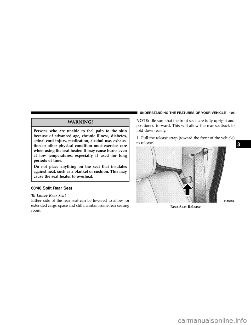
1. Pull the release strap (toward the front of the vehicle)
to release.
Rear Seat Release
UNDERSTANDING THE FEATURES OF YOUR VEHICLE 105
3
Page 235 of 395

Extreme Cold Weather (below ±20ÉF (±29ÉC)
To insure reliable starting at these temperatures, use of an
externally powered electric engine block heater (available
from your authorized dealer) is recommended.
If Engine Fails to Start
If the engine fails to start after you have followed the
ªNormal Startingº or ªExtreme Cold Weatherº proce-
dures, it may be flooded. Push the accelerator pedal all
the way to the floor and hold it there while cranking the
engine. This should clear any excess fuel in case the
engine is flooded.
CAUTION!
To prevent damage to the starter, do not crank the
engine for more than 15 seconds at a time. Wait 10 to
15 seconds before trying again.
Ignition Key Positions
STARTING AND OPERATING 235
5
Page 293 of 395

IF YOUR ENGINE OVERHEATS
In any of the following situations, you can reduce the
potential for overheating by taking the appropriate ac-
tion.
²On the highways Ð Slow down.
²In city traffic Ð While stopped, put transmission in N
(Neutral), but do not increase engine idle speed.
NOTE:There are steps that you can take to slow down
an impending overheat condition. If your air conditioner
is on, turn it off. The air conditioning system adds heat to
the engine cooling system and turning off the A/C
removes this heat. You can also turn the Temperature
Control to maximum heat, the Mode Control to floor, and
the Fan Control to High. This allows the heater core to act
as a supplement to the radiator and aids in removing heat
from the engine cooling system.
CAUTION!
Driving with a hot cooling system could damage
your vehicle. If the temperature gauge reads ªHº,
pull over and stop the vehicle. Idle the vehicle with
the air conditioner turned off until the pointer drops
back into the normal range. If the pointer remains on
the ªHº, and you hear continuous chimes, turn the
engine off immediately, and call for service.
JUMP STARTING
If the vehicle has a discharged battery, booster cables may
be used to obtain a start from a booster battery or the
battery in another vehicle. This type of start can be
dangerous if done improperly, so follow this procedure
carefully.
WHAT TO DO IN EMERGENCIES 293
6
Page 294 of 395

WARNING!
Battery fluid is a corrosive acid solution; do not
allow battery fluid to contact eyes, skin or clothing.
Don't lean over battery when attaching clamps or
allow the clamps to touch each other. If acid splashes
in eyes or on skin, flush contaminated area immedi-
ately with large quantities of water.
A battery generates hydrogen gas which is flam-
mable and explosive. Keep flame or spark away
from the vent holes.
Do not use a booster battery or any other booster
source that has a greater than 12 volt system, i.e. Do
not use a 24 volt power source.
1. Remove all metal jewelry such as watch bands or
bracelets which might make an unintended electrical
contact.2. Park the booster vehicle within cable reach but with-
out letting the vehicles touch. Set the parking brake on
both vehicles, place the transmission in P (Park), and turn
the ignition OFF.
3. Turn off the heater, radio, and all unnecessary electri-
cal loads.
4. Connect one end of a jumper cable to the positive
terminal of the booster battery. Connect the other end of
the same cable to the positive terminal of the discharged
battery.
WARNING!
Do not permit vehicles to touch each other as this
could establish a ground connection and personal
injury could result.
294 WHAT TO DO IN EMERGENCIES
Page 295 of 395

1. Remove all metal jewelry such as watch bands or
bracelets which might make an unintended electrical
contact.
2. Park the booster vehicle within cable reach but with-
out letting the vehicles touch. Set the parking brake on
both vehicles, place the transmission in P (Park), and turn
the ignition OFF.
3. Turn off the heater, radio, and all unnecessary electri-
cal loads.
4. Connect one end of a jumper cable to the positive
terminal of the booster battery. Connect the other end of
the same cable to the positive terminal of the discharged
battery.WARNING!
Do not permit vehicles to touch each other as this
could establish a ground connection and personal
injury could result.
5. Connect the other cable, first to the negative terminal
of the booster battery and then to the engine of the
vehicle with the discharged battery. Make sure you have
a good contact on the engine.
6. Start the engine in the vehicle which has the booster
battery, let the engine idle a few minutes, then start the
engine in the vehicle with the discharged battery.
7. When removing the jumper cables, reverse the above
sequence exactly. Be careful of the moving belts and fan.
WHAT TO DO IN EMERGENCIES 295
6
Page 334 of 395

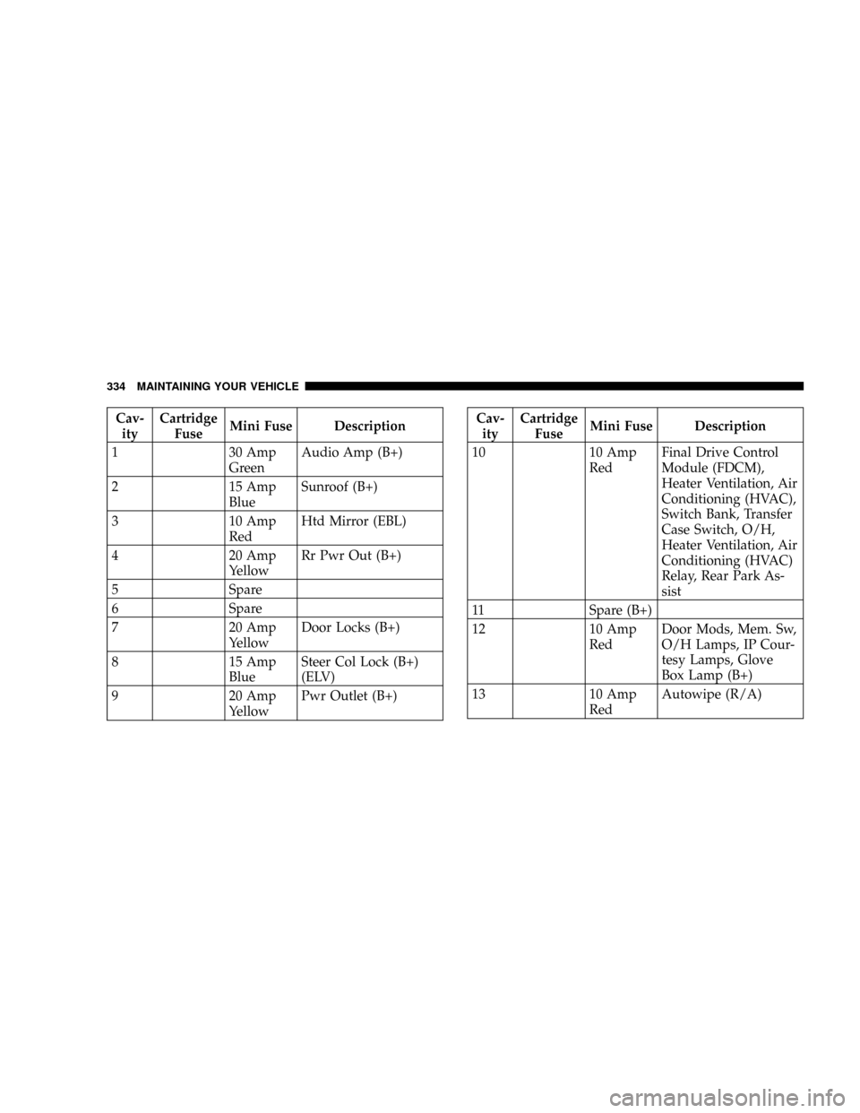
Cav-
ityCartridge
FuseMini Fuse Description
1 30 Amp
GreenAudio Amp (B+)
2 15 Amp
BlueSunroof (B+)
3 10 Amp
RedHtd Mirror (EBL)
4 20 Amp
YellowRr Pwr Out (B+)
5 Spare
6 Spare
7 20 Amp
YellowDoor Locks (B+)
8 15 Amp
BlueSteer Col Lock (B+)
(ELV)
9 20 Amp
YellowPwr Outlet (B+)Cav-
ityCartridge
FuseMini Fuse Description
10 10 Amp
RedFinal Drive Control
Module (FDCM),
Heater Ventilation, Air
Conditioning (HVAC),
Switch Bank, Transfer
Case Switch, O/H,
Heater Ventilation, Air
Conditioning (HVAC)
Relay, Rear Park As-
sist
11 Spare (B+)
12 10 Amp
RedDoor Mods, Mem. Sw,
O/H Lamps, IP Cour-
tesy Lamps, Glove
Box Lamp (B+)
13 10 Amp
RedAutowipe (R/A)
334 MAINTAINING YOUR VEHICLE
Page 346 of 395

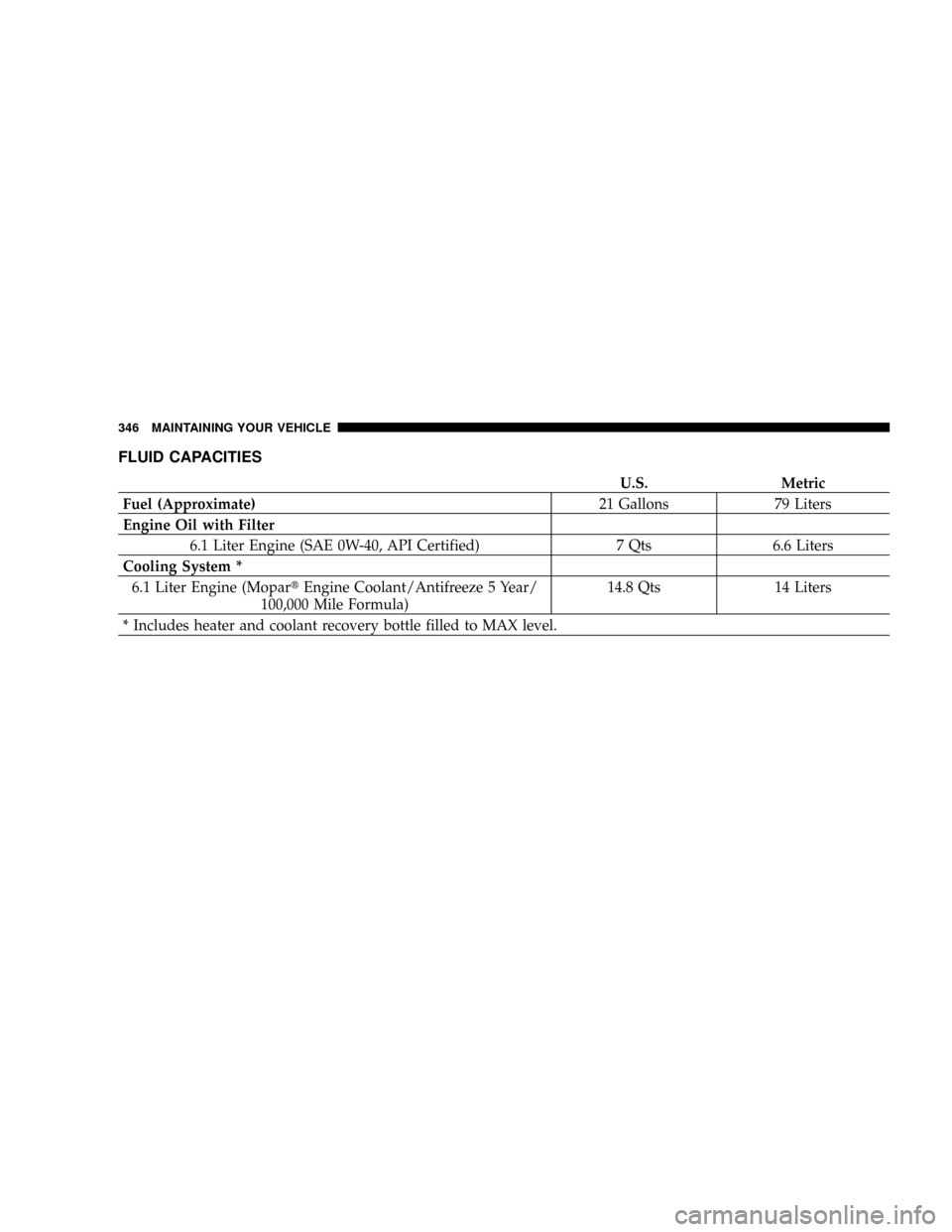
FLUID CAPACITIES
U.S. Metric
Fuel (Approximate)21 Gallons 79 Liters
Engine Oil with Filter
6.1 Liter Engine (SAE 0W-40, API Certified) 7 Qts 6.6 Liters
Cooling System *
6.1 Liter Engine (MopartEngine Coolant/Antifreeze 5 Year/
100,000 Mile Formula)14.8 Qts 14 Liters
* Includes heater and coolant recovery bottle filled to MAX level.
346 MAINTAINING YOUR VEHICLE