ignition JEEP GRAND CHEROKEE 2010 WK / 3.G Owner's Manual
[x] Cancel search | Manufacturer: JEEP, Model Year: 2010, Model line: GRAND CHEROKEE, Model: JEEP GRAND CHEROKEE 2010 WK / 3.GPages: 84, PDF Size: 14.64 MB
Page 56 of 84

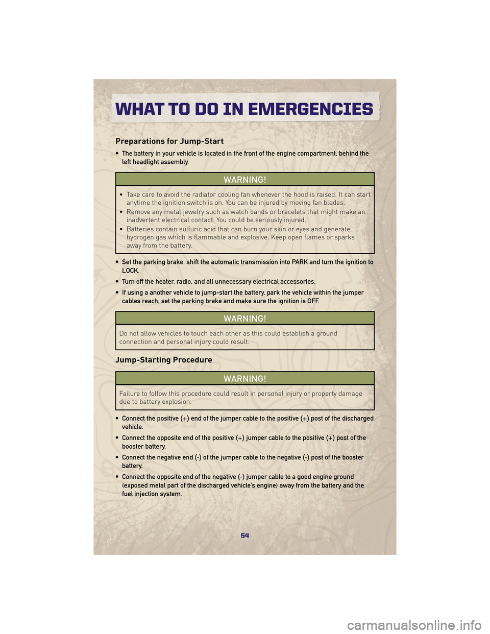
Preparations for Jump-Start
• The battery in your vehicle is located in the front of the engine compartment, behind theleft headlight assembly.
WARNING!
• Take care to avoid the radiator cooling fan whenever the hood is raised. It can start anytime the ignition switch is on. You can be injured by moving fan blades.
• Remove any metal jewelry such as watch bands or bracelets that might make an inadvertent electrical contact. You could be seriously injured.
• Batteries contain sulfuric acid that can burn your skin or eyes and generate hydrogen gas which is flammable and explosive. Keep open flames or sparks
away from the battery.
• Set the parking brake, shift the automatic transmission into PARK and turn the ignition to LOCK.
• Turn off the heater, radio, and all unnecessary electrical accessories.
• If using a another vehicle to jump-start the battery, park the vehicle within the jumper cables reach, set the parking brake and make sure the ignition is OFF.
WARNING!
Do not allow vehicles to touch each other as this could establish a ground
connection and personal injury could result.
Jump-Starting Procedure
WARNING!
Failure to follow this procedure could result in personal injury or property damage
due to battery explosion.
• Connect the positive (+)end of the jumper cable to the positive (+)post of the discharged
vehicle.
• Connect the opposite end of the positive (+)jumper cable to the positive (+)post of the
booster battery.
• Connect the negative end (-)of the jumper cable to the negative (-)post of the booster
battery.
• Connect the opposite end of the negative (-)jumper cable to a good engine ground
(exposed metal part of the discharged vehicle’s engine) away from the battery and the
fuel injection system.
WHAT TO DO IN EMERGENCIES
54
Page 71 of 84

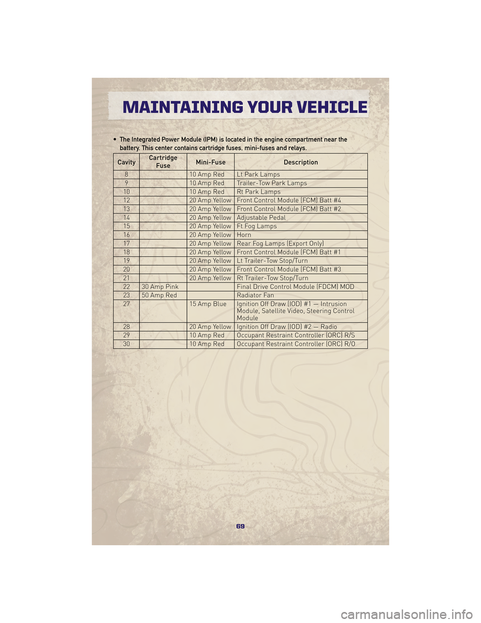
• The Integrated Power Module (IPM) is located in the engine compartment near thebattery. This center contains cartridge fuses, mini-fuses and relays.
Cavity Cartridge
Fuse Mini-Fuse
Description
8 10 Amp Red Lt Park Lamps
9 10 Amp Red Trailer-Tow Park Lamps
10 10 Amp Red Rt Park Lamps
12 20 Amp Yellow Front Control Module (FCM) Batt #4
13 20 Amp Yellow Front Control Module (FCM) Batt #2
14 20 Amp Yellow Adjustable Pedal
15 20 Amp Yellow Ft Fog Lamps
16 20 Amp Yellow Horn
17 20 Amp Yellow Rear Fog Lamps (Export Only)
18 20 Amp Yellow Front Control Module (FCM) Batt #1
19 20 Amp Yellow Lt Trailer-Tow Stop/Turn
20 20 Amp Yellow Front Control Module (FCM) Batt #3
21 20 Amp Yellow Rt Trailer-Tow Stop/Turn
22 30 Amp Pink Final Drive Control Module (FDCM) MOD
23 50 Amp Red Radiator Fan
27 15 Amp Blue Ignition Off Draw (IOD) #1 — Intrusion
Module, Satellite Video, Steering Control
Module
28 20 Amp Yellow Ignition Off Draw (IOD) #2 — Radio
29 10 Amp Red Occupant Restraint Controller (ORC) R/S
30 10 Amp Red Occupant Restraint Controller (ORC) R/O
69
MAINTAINING YOUR VEHICLE
Page 73 of 84

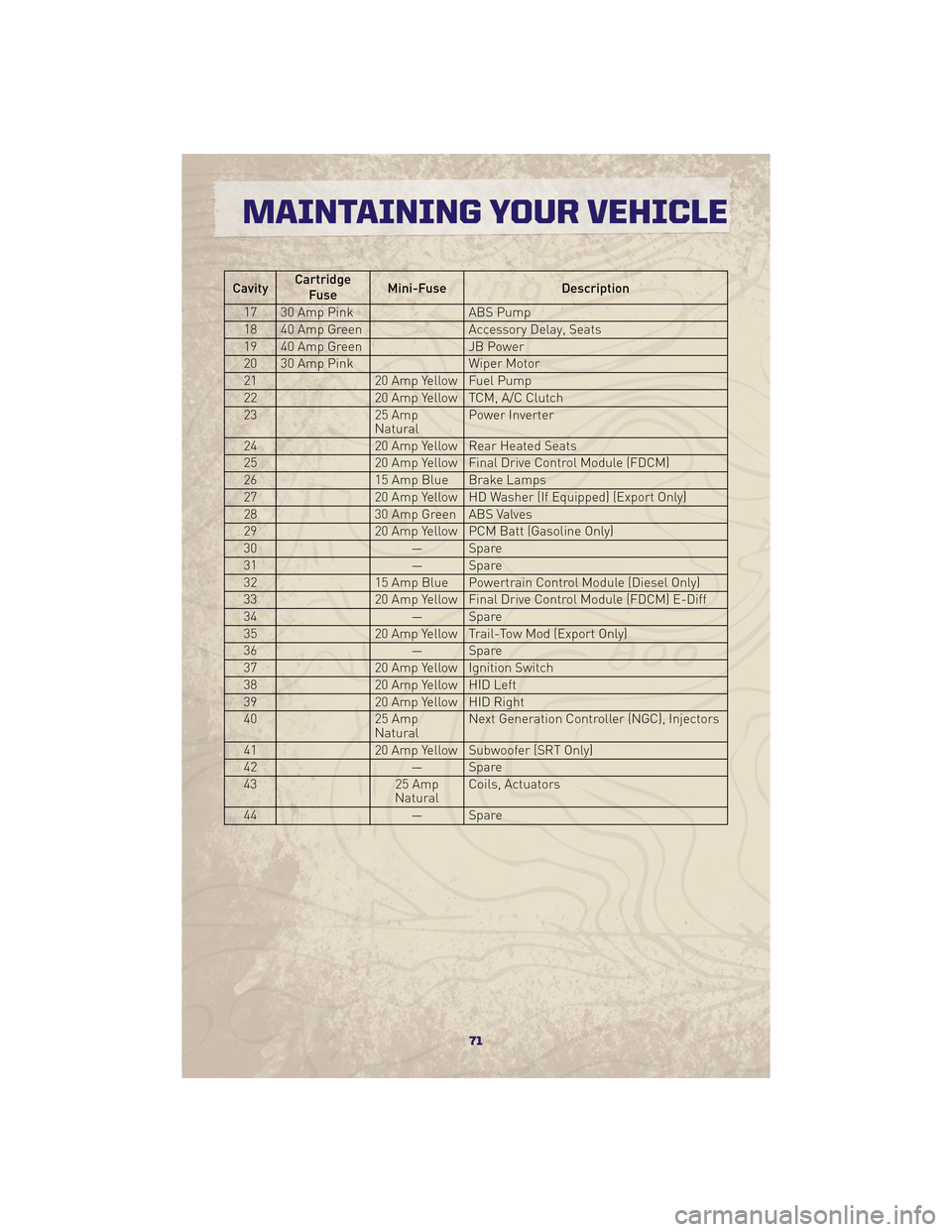
CavityCartridge
Fuse Mini-Fuse
Description
17 30 Amp Pink ABS Pump
18 40 Amp Green Accessory Delay, Seats
19 40 Amp Green JB Power
20 30 Amp Pink Wiper Motor
21 20 Amp Yellow Fuel Pump
22 20 Amp Yellow TCM, A/C Clutch
23 25 Amp
NaturalPower Inverter
24 20 Amp Yellow Rear Heated Seats
25 20 Amp Yellow Final Drive Control Module (FDCM)
26 15 Amp Blue Brake Lamps
27 20 Amp Yellow HD Washer (If Equipped) (Export Only)
28 30 Amp Green ABS Valves
29 20 Amp Yellow PCM Batt (Gasoline Only)
30 — Spare
31 — Spare
32 15 Amp Blue Powertrain Control Module (Diesel Only)
33 20 Amp Yellow Final Drive Control Module (FDCM) E-Diff
34 — Spare
35 20 Amp Yellow Trail-Tow Mod (Export Only)
36 — Spare
37 20 Amp Yellow Ignition Switch
38 20 Amp Yellow HID Left
39 20 Amp Yellow HID Right
40 25 Amp
NaturalNext Generation Controller (NGC), Injectors
41 20 Amp Yellow Subwoofer (SRT Only)
42 — Spare
43 25 Amp
Natural Coils, Actuators
44 — Spare
71
MAINTAINING YOUR VEHICLE