battery JEEP GRAND CHEROKEE 2010 WK / 3.G User Guide
[x] Cancel search | Manufacturer: JEEP, Model Year: 2010, Model line: GRAND CHEROKEE, Model: JEEP GRAND CHEROKEE 2010 WK / 3.GPages: 84, PDF Size: 14.64 MB
Page 11 of 84
WARNING!
• Do not start or run an engine in a closed garage or confined area. Exhaust gascontains Carbon Monoxide (CO) which is odorless and colorless. Carbon Monoxide
is poisonous and can cause serious injury or death when inhaled.
• Keep Key Fob transmitters away from children. Operation of the Remote Start System, windows, door locks or other controls could cause serious injury or
death.
Panic Alarm
• Press the PANIC button once to turn the panic alarm on.
• Wait approximately three seconds and press the button a second time to turn the panic
alarm off.
Express Window Feature
• To remotely lower both front door windows at the same time, press and release theUNLOCK button and then immediately press and hold the UNLOCK button until the
windows lower to the level desired or until they lower completely.
Emergency Key
• Should the battery in the vehicle or the Key Fob transmitter go dead, there is anemergency key located in the Key Fob. To remove the emergency key, slide the button at
the top of the Key Fob sideways with your thumb and then pull the key out with your
other hand.
• The emergency key is also for locking the glove compartment.
THEFT ALARM
To Arm
• Press the Key Fob LOCK button or the power door lock switch while the door is open.
To Disarm
• Press the Key Fob UNLOCK button and turn the ignition to the ON position.
SEAT BELT
• Be sure everyone in your vehicle is in a seat and using a seat belt properly.
WARNING!
In a collision, you and your passengers can suffer much greater injuries if you are
not properly buckled up. You can strike the interior of your vehicle or other
passengers, or you can be thrown out of the vehicle. Always be sure you and others
in your vehicle are buckled up properly.
9
GETTING STARTED
Page 37 of 84
POWER INVERTER
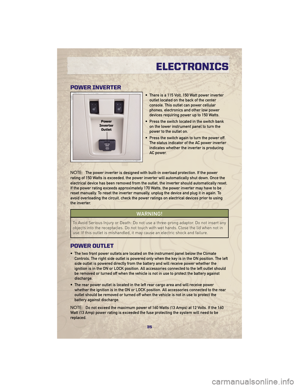
• There is a 115 Volt, 150 Watt power inverteroutlet located on the back of the center
console. This outlet can power cellular
phones, electronics and other low power
devices requiring power up to 150 Watts.
• Press the switch located in the switch bank on the lower instrument panel to turn the
power to the outlet on.
• Press the switch again to turn the power off. The status indicator of the AC power inverter
indicates whether the inverter is producing
AC power.
NOTE: The power inverter is designed with built-in overload protection. If the power
rating of 150 Watts is exceeded, the power inverter will automatically shut down. Once the
electrical device has been removed from the outlet, the inverter should automatically reset.
If the power rating exceeds approximately 170 Watts, the power inverter may have to be
reset manually. To reset the inverter manually, unplug the device and plug it in again. To
avoid overloading the circuit, check the power ratings on electrical devices prior to using
the inverter.
WARNING!
To Avoid Serious Injury or Death: Do not use a three-prong adaptor. Do not insert any
objects into the receptacles. Do not touch with wet hands. Close the lid when not in
use. If this outlet is mishandled, it may cause an electric shock and failure.
POWER OUTLET
• The two front power outlets are located on the instrument panel below the Climate Controls. The right side outlet is powered only when the key is in the ON position. The left
side outlet is powered directly from the battery and will receive power whether the
ignition is in the ON or LOCK position. All accessories connected to the left outlet should
be removed or turned off when the vehicle is not in use to protect the battery against
discharge.
• The rear power outlet is located in the left rear cargo area and will receive power whether the ignition is in the ON or LOCK position. All accessories connected to the rear
outlet should be removed or turned off when the vehicle is not in use to protect the
battery against discharge.
NOTE: Do not exceed the maximum power of 160 Watts (13 Amps) at 12 Volts. If the 160
Watt (13 Amp) power rating is exceeded the fuse protecting the system will need to be
replaced.
35
ELECTRONICS
Page 55 of 84
JUMP-STARTING
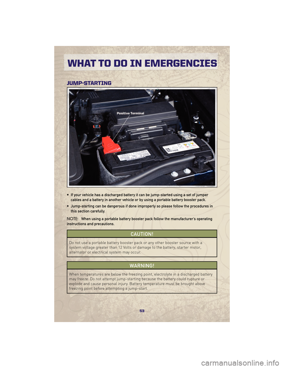
• If your vehicle has a discharged battery it can be jump-started using a set of jumpercables and a battery in another vehicle or by using a portable battery booster pack.
• Jump-starting can be dangerous if done improperly so please follow the procedures in this section carefully.
NOTE: When using a portable battery booster pack follow the manufacturer’s operating
instructions and precautions.
CAUTION!
Do not use a portable battery booster pack or any other booster source with a
system voltage greater than 12 Volts or damage to the battery, starter motor,
alternator or electrical system may occur.
WARNING!
When temperatures are below the freezing point, electrolyte in a discharged battery
may freeze. Do not attempt jump-starting because the battery could rupture or
explode and cause personal injury. Battery temperature must be brought above
freezing point before attempting a jump-start.
53
WHAT TO DO IN EMERGENCIES
Page 56 of 84
Preparations for Jump-Start
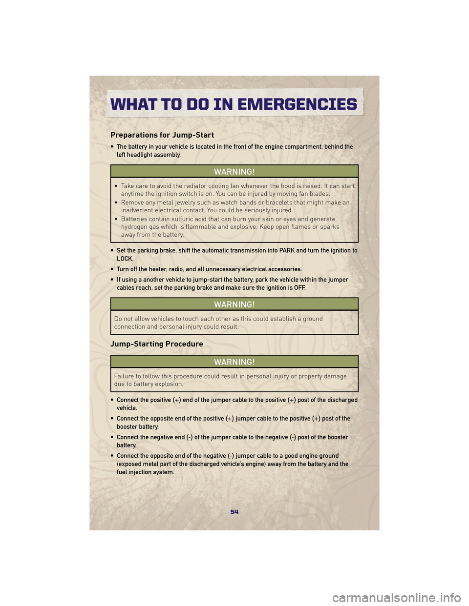
• The battery in your vehicle is located in the front of the engine compartment, behind theleft headlight assembly.
WARNING!
• Take care to avoid the radiator cooling fan whenever the hood is raised. It can start anytime the ignition switch is on. You can be injured by moving fan blades.
• Remove any metal jewelry such as watch bands or bracelets that might make an inadvertent electrical contact. You could be seriously injured.
• Batteries contain sulfuric acid that can burn your skin or eyes and generate hydrogen gas which is flammable and explosive. Keep open flames or sparks
away from the battery.
• Set the parking brake, shift the automatic transmission into PARK and turn the ignition to LOCK.
• Turn off the heater, radio, and all unnecessary electrical accessories.
• If using a another vehicle to jump-start the battery, park the vehicle within the jumper cables reach, set the parking brake and make sure the ignition is OFF.
WARNING!
Do not allow vehicles to touch each other as this could establish a ground
connection and personal injury could result.
Jump-Starting Procedure
WARNING!
Failure to follow this procedure could result in personal injury or property damage
due to battery explosion.
• Connect the positive (+)end of the jumper cable to the positive (+)post of the discharged
vehicle.
• Connect the opposite end of the positive (+)jumper cable to the positive (+)post of the
booster battery.
• Connect the negative end (-)of the jumper cable to the negative (-)post of the booster
battery.
• Connect the opposite end of the negative (-)jumper cable to a good engine ground
(exposed metal part of the discharged vehicle’s engine) away from the battery and the
fuel injection system.
WHAT TO DO IN EMERGENCIES
54
Page 57 of 84
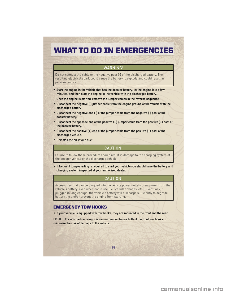
WARNING!
Do not connect the cable to the negative post(-)of the discharged battery. The
resulting electrical spark could cause the battery to explode and could result in
personal injury.
• Start the engine in the vehicle that has the booster battery, let the engine idle a few minutes, and then start the engine in the vehicle with the discharged battery.
Once the engine is started, remove the jumper cables in the reverse sequence:
• Disconnect the negative (-)jumper cable from the engine ground of the vehicle with the
discharged battery.
• Disconnect the negative end (-)of the jumper cable from the negative (-)post of the
booster battery.
• Disconnect the opposite end of the positive (+)jumper cable from the positive (+)post of
the booster battery.
• Disconnect the positive (+)end of the jumper cable from the positive (+)post of the
discharged vehicle.
• Reinstall the air intake duct.
CAUTION!
Failure to follow these procedures could result in damage to the charging system of
the booster vehicle or the discharged vehicle.
• If frequent jump-starting is required to start your vehicle you should have the battery and charging system inspected at your authorized dealer.
CAUTION!
Accessories that can be plugged into the vehicle power outlets draw power from the
vehicle’s battery, even when not in use (i.e., cellular phones, etc.). Eventually, if
plugged in long enough, the vehicle’s battery will discharge sufficiently to degrade
battery life and/or prevent the engine from starting.
EMERGENCY TOW HOOKS
• If your vehicle is equipped with tow hooks, they are mounted in the front and the rear.
NOTE: For off-road recovery, it is recommended to use both of the front tow hooks to
minimize the risk of damage to the vehicle.
55
WHAT TO DO IN EMERGENCIES
Page 71 of 84
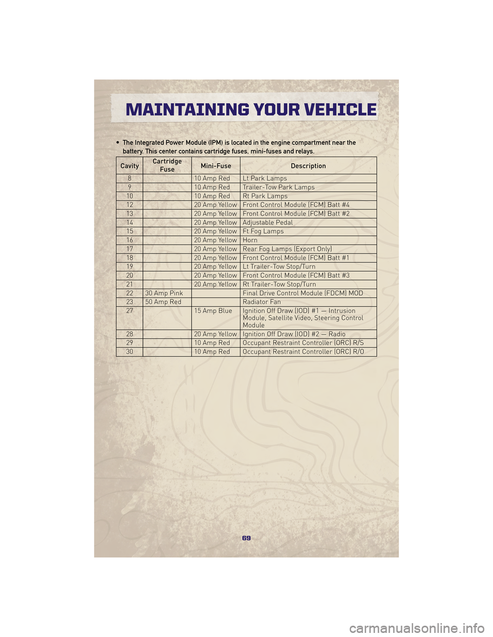
• The Integrated Power Module (IPM) is located in the engine compartment near thebattery. This center contains cartridge fuses, mini-fuses and relays.
Cavity Cartridge
Fuse Mini-Fuse
Description
8 10 Amp Red Lt Park Lamps
9 10 Amp Red Trailer-Tow Park Lamps
10 10 Amp Red Rt Park Lamps
12 20 Amp Yellow Front Control Module (FCM) Batt #4
13 20 Amp Yellow Front Control Module (FCM) Batt #2
14 20 Amp Yellow Adjustable Pedal
15 20 Amp Yellow Ft Fog Lamps
16 20 Amp Yellow Horn
17 20 Amp Yellow Rear Fog Lamps (Export Only)
18 20 Amp Yellow Front Control Module (FCM) Batt #1
19 20 Amp Yellow Lt Trailer-Tow Stop/Turn
20 20 Amp Yellow Front Control Module (FCM) Batt #3
21 20 Amp Yellow Rt Trailer-Tow Stop/Turn
22 30 Amp Pink Final Drive Control Module (FDCM) MOD
23 50 Amp Red Radiator Fan
27 15 Amp Blue Ignition Off Draw (IOD) #1 — Intrusion
Module, Satellite Video, Steering Control
Module
28 20 Amp Yellow Ignition Off Draw (IOD) #2 — Radio
29 10 Amp Red Occupant Restraint Controller (ORC) R/S
30 10 Amp Red Occupant Restraint Controller (ORC) R/O
69
MAINTAINING YOUR VEHICLE