ignition JEEP GRAND CHEROKEE 2012 WK2 / 4.G Owner's Manual
[x] Cancel search | Manufacturer: JEEP, Model Year: 2012, Model line: GRAND CHEROKEE, Model: JEEP GRAND CHEROKEE 2012 WK2 / 4.GPages: 148, PDF Size: 5.91 MB
Page 85 of 148
• The power outlets are labeled with either a “key” or a “battery” symbolto indicate how the outlet is powered. Power outlets labeled with a “key”
are powered when the ignition switch is in the ON/RUN or ACC position,
while the outlets labeled with a “battery” are connected directly to the
battery and powered at all times.
NOTE:
• Do not exceed the maximum power of 160 Watts (13 Amps) at 12 Volts. If the 160 Watt (13 Amp) power rating is exceeded, the fuse protecting the
system will need to be replaced.
• Power outlets are designed for accessory plugs only. Do not insert any other object in the power outlet as this will damage the outlet and blow
the fuse. Improper use of the power outlet can cause damage not covered
by your new vehicle warranty.
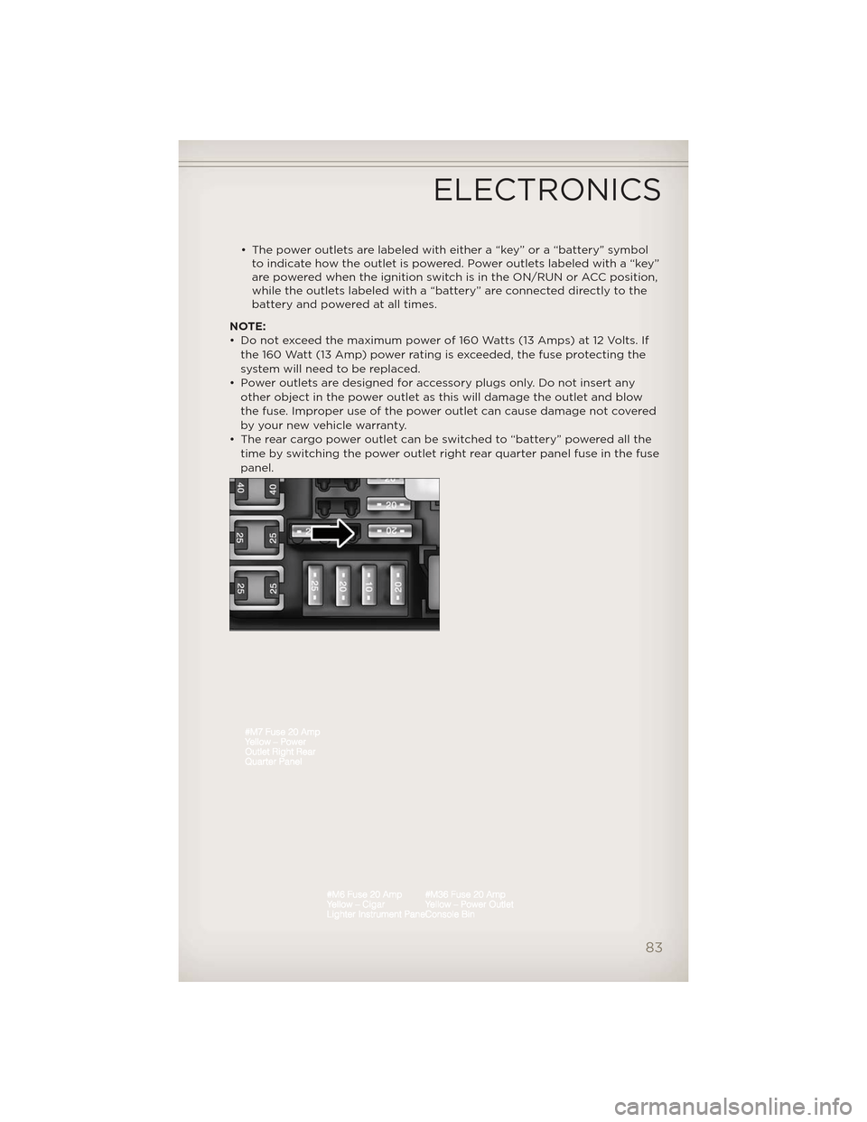
• The rear cargo power outlet can be switched to “battery” powered all the time by switching the power outlet right rear quarter panel fuse in the fuse
panel.
ELECTRONICS
83
Page 87 of 148
Shifting Procedures
4WD HI To 4WD LOW• With the vehicle at speeds of 0 to 3 mph (0 to 5 km/h), the ignition switch in the ON/RUN position or the engine running, shift the
transmission into NEUTRAL, and press the “4WD LOW” button once on
the transfer case switch. The “4WD LOW” indicator light in the
instrument cluster will begin to flash and remain on solid when the shift
is complete.
4WD LOW To 4WD HI • With the vehicle at speeds of 0 to 3 mph (0 to 5 km/h), the ignition switch in the ON/RUN position or the engine running, shift the
transmission into NEUTRAL, and press the “4WD LOW” button once on
the transfer case switch. The “4WD LOW” indicator light in the
instrument cluster will flash and turn off when the shift is complete.
NOTE:
• If the shift conditions/interlocks are not met, or a transfer case motor temperature protection exists, a “For 4x4 Low Slow Below 5 MPH or 8 KPH
Put Trans in N Press 4 Low” message will flash on the Electronic Vehicle
Information Center (EVIC).
• Shifting into or out of 4WD LOW is possible with the vehicle completely stopped; however, d ifficulty may occur due to the mating clutch teeth not
being properly aligned. Several attempts may be required for clutch teeth
alignment and shift completion to occur. The preferred method is with the
vehicle rolling 0 to 3 mph (0 to 5 km/h). If the vehicle is moving faster than
3 mph (5 km/h), the transfer case will not allow the shift.
NEUTRAL Shift Procedure
• Turn the ignition switch to the ON/RUN position, engine off.
• Vehicle stopped, with foot on brake.
• Place the transmission into NEUTRAL.
• Press and hold the NEUTRAL button located near the 4WD mode control knob with a pen or similar object for four seconds. The indicator light will
begin to flash indicating the shift is in progress. The light will stop
blinking (stay on solid) when the NEUTRAL shift is complete. A “4WD
SYSTEM IN NEUTRAL” message will display on the Electronic Vehicle
Information Center (EVIC).
• Repeat these Steps to shift out of NEUTRAL.
OFF-ROAD CAPABILITIES
85
Page 93 of 148
• For vehicles with Keyless Enter-N-Go™, remove the Keyless Enter-N-Go™button and use the Key Fob to complete this procedure.
• Turn the ignition switch to the ON/RUN position, but do not start the engine.
• Press and hold the brake pedal and shift the transmission into NEUTRAL.
• Using a ballpoint pen or similar object, press and hold the recessed transfer case N (Neutral) button for four seconds, until the light next to
the N symbol starts to blink, indicating shift in progress. The light will
stop blinking (stay on solid) when the shift to N (Neutral) is complete. A
“FOUR WHEEL DRIVE SYSTEM IN NEUTRAL” message will display on
the EVIC (Electronic Vehicle Information Center).
• Start the engine and shift the transmission into REVERSE.
• Release the brake pedal for five seconds and ensure that there is no vehicle movement.
• Turn the engine off and firmly apply the parking brake.
• Shift the transmission into PARK and remove the Key Fob.
• Attach the vehicle to the tow vehicle using a suitable tow bar and release the parking brake.
NOTE: Vehicles equipped with Quadra-Lift™ must be lowered to the “Park”
(lowest) level, and have automatic leveling disabled, before tying them down
(from the body) on a trailer or a flatbed truck. Refer to “Quadra-Lift™” in
“Off-Road Capabilities” for more information. If the vehicle cannot be
lowered to the “Park” level (for example, engine will not run), tie-downs must
be fastened to the axles (not the body). Failure to follow these instructions
may cause fault codes to be set and/or loss of proper tie-down tension.
CAUTION!
• Towing with the rear wheels on the ground will cause severe transmission damage. Damage from improper towing is not covered
under the New Vehicle Limited Warranty.
• Front or rear wheel lifts should not be used. Internal damage to the transmission or transfer case will occur if a front or rear wheel lift is
used when recreational towing.
• It is necessary to follow these steps to be certain that the transfer case is fully in NEUTRAL before recreational towing to prevent
damage to internal parts.
UTILITY
91
Page 101 of 148
- Malfunction Indicator Light (MIL)
• Certain conditions, such as a loose or missing gas cap, poor fuel quality,etc., may illuminate the MIL after engine start. The vehicle should be
serviced if the light stays on through several typical driving cycles. In
most situations, the vehicle will drive normally and not require towing.
• If the MIL flashes when the engine is running, serious conditions may exist that could lead to immediate loss of power or severe catalytic
converter damage. We recommend you do not operate the vehicle. Have
the vehicle serviced immediately.
- Electronic Stability Control (ESC) Activation/MalfunctionIndicator Light
• If the “ESC Activation/Malfunction Indicator Light” comes on
continuously with the engine running, a malfunction has been detected
in the ESC system. If this light remains on after several ignition cycles,
and the vehicle has been driven several miles (kilometers) at speeds
greater than 30 mph (48 km/h), we recommend you drive to the nearest
service center and have the vehicle serviced immediately.
• The “ESC Activation/Malfunction Indicator Light” starts to flash as soon as the tires lose traction and the ESC system becomes active. If the light
begins to flash during acceleration, ease up on the accelerator and apply
as little throttle as possible. Be sure to adapt your speed and driving to
the prevailing road conditions. The light also flashes when TCS is active.
To improve the vehicle's traction when starting off in deep snow, sand or
gravel, it may be desirable to switch the ESC system to Partial Off mode
by momentarily pressing the ESC Off
switch located below the
climate controls, on the switch panel.
- Charging System Light
• This light shows the status of the electrical charging system. If the charging system light remains on, it means that the vehicle is
experiencing a problem with the charging system.
• We recommend you do not continue driving if the charging system light is on. Have the vehicle serviced immediately.
- Oil Pressure Warning Light
• This light indicates low engine oil pressure. If the light turns on whiledriving, stop the vehicle and shut off the engine as soon as possible. A
chime will sound for four minutes when this light turns on.
• We recommend you do not operate the vehicle or engine damage will occur. Have the vehicle serviced immediately.
- Anti-Lock Brake (ABS) Light
• This light monitors the Anti-Lock Brake System (ABS).
• If the light is not on during starting, stays on, or turns on while driving,we recommend you drive to the nearest service center and have the
vehicle serviced immediately.
WHAT TO DO IN EMERGENCIES
99
Page 102 of 148
- Electronic Throttle Control (ETC) Light
• This light informs you of a problem with the Electronic Throttle Control(ETC) system.
• If a problem is detected, the light will come on while the engine is running. Cycle the ignition key when the vehicle has completely stopped
and the shift lever is placed in the PARK position; the light should turn
off.
• If the light remains lit with the engine running, your vehicle will usually be drivable; however, see an authorized service center i mmediately. If the
light is flashing when the engine is running, immediate service is required
and you may experience reduced performance, an elevated/rough idle or
engine stall and your vehicle may require towing.
- Air Bag Warning Light
• If the light is not on during starting, stays on, or turns on while driving, have the vehicle serviced by an authorized service center immediately.
Fuel Cap/Loose Gas Cap Message
• If a “gas cap” message (shown as Check Gascap) appears, tighten thegas cap until a “clicking” sound is heard.
• If the message continues to appear for more than three days after tightening the gas cap, have the vehicle serviced by an authorized
service center immediately.
Oil Change IndicatorMessage
• If an “oil change” message (shown as Oil Change Required) appears and a single chime sounds, it is time for your next required oil change.
Resetting The Light After Servicing
Vehicles Equipped With Keyless Enter-N-Go™ • Without pressing the brake pedal, push the ENGINE START/STOP button and cycle the ignition to the ON/RUN position (Do not start the engine.)
• Fully depress the accelerator pedal, slowly, three times within 10 seconds.
• Without pressing the brake pedal, push the ENGINE START/STOP button once to return the ignition to the OFF/LOCK position.
Vehicles Not Equipped With Keyless Enter-N-Go™
• Turn the ignition switch to the ON/RUN position (Do not start the engine.)
• Fully depress the accelerator pedal, slowly, three times within 10 seconds.
• Turn the ignition switch to the OFF/LOCK position.
WHAT TO DO IN EMERGENCIES
100
Page 106 of 148
Preparations For Jacking
1. Park the vehicle on a firm, level surface. Avoid ice or slippery surfaces.
2. Turn on the Hazard Warning flasher.
3. Set the parking brake.
4. Place the shift lever into PARK.
5. Turn the ignition OFF.
6. For vehicle equipped with Quadra-Lift® refer to “Quadra-Lift — IfEquipped” in “Starting And Operating” on the DVD for further
information on disabling automatic leveling.
Block both the front and rear of the
wheel diagonally opposite of the
jacking position. For example, if
changing the right front tire, block the
left rear wheel.
NOTE:Passengers should not remain
in the vehicle when the vehicle is
being jacked.
Jacking Instructions
1. Remove the spare tire, jack, and tools from storage.
2. Loosen (but do not remove) the wheel lug nuts by turning them to
the left, one turn, while the wheel
is still on the ground.
3. Assemble the jack and jacking tools.
WHAT TO DO IN EMERGENCIES
104
Page 111 of 148
Preparations for Jump-Start
• The battery in your vehicle islocated under the passengers
front seat. There are remote
locations under the hood to assist
in jump starting.
• Set the parking brake, shift the automatic transmission into PARK
and turn the ignition to LOCK.
• Turn off the heater, radio, and all unnecessary electrical accessories.
• Remove the protective cover over the remote positive (+) battery
post. Pull upward on the cover to
remove it.
• If using another vehicle to jump-start the battery, park the vehicle within the jumper cables reach, set the parking brake and make sure the
ignition is OFF.
Jump-Starting Procedure
• Connect the positive (+)end of the jumper cable to the remote positive
(+) post of the discharged vehicle.
• Connect the opposite end of the positive (+)jumper cable to the positive
(+) post of the booster battery.
• Connect the negative end (-)of the jumper cable to the negative (-)post
of the booster battery.
• Connect the opposite end of the negative (-)jumper cable to the remote
negative (-)post of the vehicle with the discharged battery.
• Start the engine in the vehicle that has the booster battery, let the engine idle a few minutes, and then start the engine in the vehicle with the
discharged battery.
Once the engine is started, remove the jumper cables in the reverse
sequence:
• Disconnect the negative (-)jumper cable from the remote negative (-)
post of the vehicle with the discharged battery.
• Disconnect the negative end (-)of the jumper cable from the negative
(-) post of the booster battery.
• Disconnect the opposite end of the positive (+)jumper cable from the
positive (+)post of the booster battery.
• Disconnect the positive (+)end of the jumper cable from the remote
positive (+)post of the discharged vehicle.
• Reinstall the protective cover over the remote positive (+)battery post
of the discharged vehicle.
WHAT TO DO IN EMERGENCIES
109
Page 112 of 148
• If frequent jump-starting is required to start your vehicle you should havethe battery and charging system inspected at your authorized dealer.
CAUTION!
• Do not use a portable battery booster pack or any other boostersource with a system voltage greater than 12 Volts or damage to the
battery, starter motor, alternator or electrical system may occur.
• Failure to follow these procedures could result in damage to the charging system of the booster vehicle or the discharged vehicle.
• Accessories that can be plugged into the vehicle power outlets draw power from the vehicle’s battery, even when not in use (i.e.,
cellular phones, etc.). Eventually, if plugged in long enough, the
vehicle’s battery will discharge sufficiently to degrade battery life
and/or prevent the engine from starting.
WARNING!
• When temperatures are below the freezing point, electrolyte in adischarged battery may freeze. Do not attempt jump-starting
because the battery could rupture or explode and cause personal
injury. Battery temperature must be brought above freezing point
before attempting a jump-start.
• Take care to avoid the radiator cooling fan whenever the hood is raised. It can start anytime the ignition switch is on. You can be
injured by moving fan blades.
• Remove any metal jewelry, such as watch bands or bracelets, that might make an inadvertent electrical contact. You could be severely
injured.
• Batteries contain sulfuric acid that can burn your skin or eyes and generate hydrogen gas which is flammable and explosive. Keep
open flames or sparks away from the battery.
• Do not allow vehicles to touch each other as this could establish a ground connection and personal injury could result.
• Failure to follow this procedure could result in personal injury or property damage due to battery explosion.
• Do not connect the cable to the negative post (-)of the discharged
battery. The resulting electrical spark could cause the battery to
explode and could result in personal injury.
WHAT TO DO IN EMERGENCIES
110
Page 113 of 148
EMERGENCY TOW HOOKS
• If your vehicle is equipped with tow hooks, they are mounted in the frontand the rear.
NOTE: For off-road recovery, it is recommended to use both of the front
tow hooks to minimize the risk of damage to the vehicle.
CAUTION!
Tow hooks are for emergency use only, to rescue a vehicle stranded
off-road. Do not use tow hooks for tow truck hookup or highway
towing. You could damage your vehicle. Tow straps are recommended
when towing the vehicle; chains may cause vehicle damage.
WARNING!
• Chains are not recommended for freeing a stuck vehicle. Chains may break, causing serious injury or death.
• Stand clear of vehicles when pulling with tow hooks. Tow straps may become disengaged, causing serious injury.
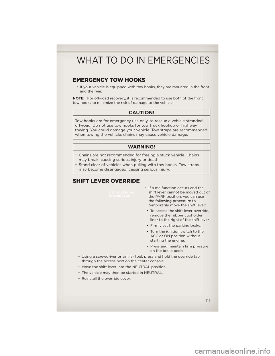
SHIFT LEVER OVERRIDE
• If a malfunction occurs and theshift lever cannot be moved out of
the PARK position, you can use
the following procedure to
temporarily move the shift lever:
• To access the shift lever override, remove the rubber cupholder
liner to the right of the shift lever.
• Firmly set the parking brake.
• Turn the ignition switch to the ACC or ON position without
starting the engine.
• Press and maintain firm pressure on the brake pedal.
• Using a screwdriver or similar tool, press and hold the override tab through the access port on the center console.
• Move the shift lever into the NEUTRAL position.
• The vehicle may then be started in NEUTRAL.
• Reinstall the override cover.
WHAT TO DO IN EMERGENCIES
111
Page 130 of 148
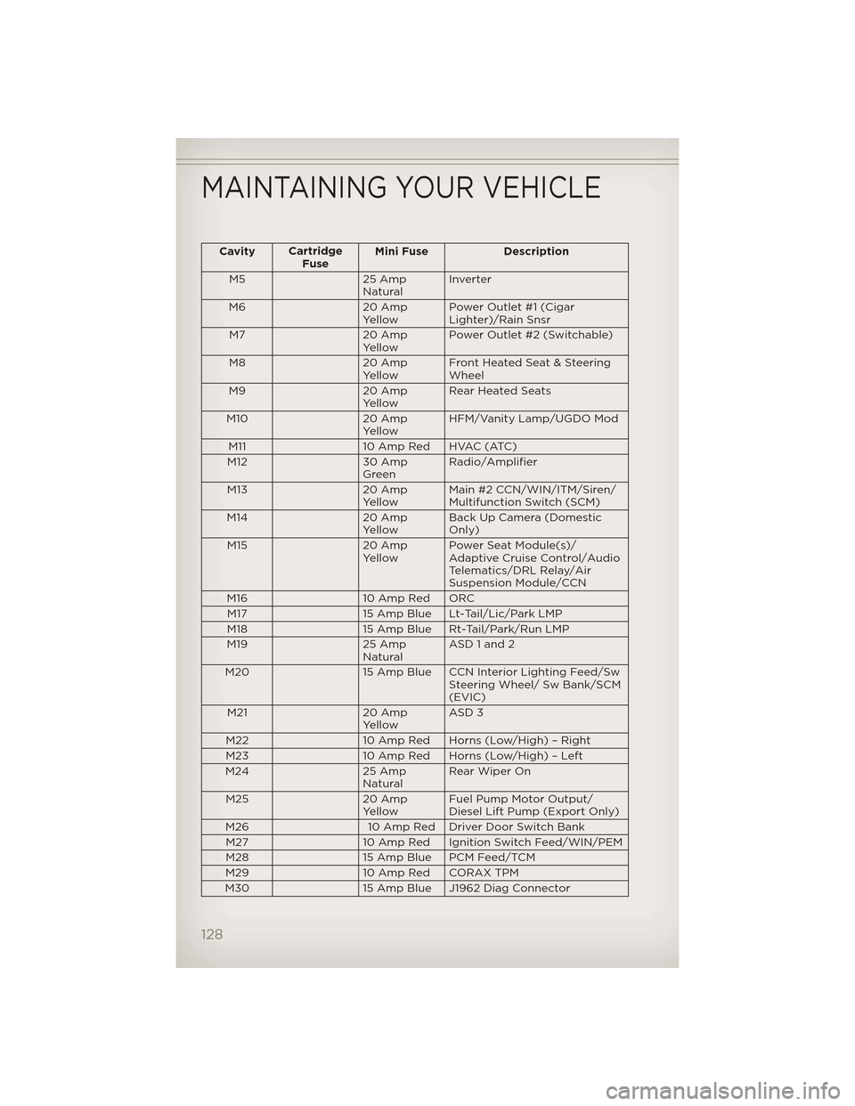
CavityCartridge
Fuse Mini Fuse Description
M5 25 Amp NaturalInverter
M6 20 Amp YellowPower Outlet #1 (Cigar
Lighter)/Rain Snsr
M7 20 Amp YellowPower Outlet #2 (Switchable)
M8 20 Amp YellowFront Heated Seat & Steering
Wheel
M9 20 Amp YellowRear Heated Seats
M10 20 Amp YellowHFM/Vanity Lamp/UGDO Mod
M11 10 Amp Red HVAC (ATC)
M12 30 Amp GreenRadio/Amplifier
M13 20 Amp
Yellow Main #2 CCN/WIN/ITM/Siren/
Multifunction Switch (SCM)
M14 20 Amp
Yellow Back Up Camera (Domestic
Only)
M15 20 Amp
Yellow Power Seat Module(s)/
Adaptive Cruise Control/Audio
Telematics/DRL Relay/Air
Suspension Module/CCN
M16 10 Amp Red ORC
M17 15 Amp Blue Lt-Tail/Lic/Park LMP
M18 15 Amp Blue Rt-Tail/Park/Run LMP
M19 25 Amp
Natural ASD 1 and 2
M20 15 Amp Blue CCN Interior Lighting Feed/Sw
Steering Wheel/ Sw Bank/SCM
(EVIC)
M21 20 Amp
Yellow ASD 3
M22 10 Amp Red Horns (Low/High) – Right
M23 10 Amp Red Horns (Low/High) – Left
M24 25 Amp
Natural Rear Wiper On
M25 20 Amp
Yellow Fuel Pump Motor Output/
Diesel Lift Pump (Export Only)
M26 10 Amp Red Driver Door Switch Bank
M27 10 Amp Red Ignition Switch Feed/WIN/PEM
M28 15 Amp Blue PCM Feed/TCM
M29 10 Amp Red CORAX TPM
M30 15 Amp Blue J1962 Diag Connector
MAINTAINING YOUR VEHICLE
128