parking brake JEEP GRAND CHEROKEE 2012 WK2 / 4.G User Guide
[x] Cancel search | Manufacturer: JEEP, Model Year: 2012, Model line: GRAND CHEROKEE, Model: JEEP GRAND CHEROKEE 2012 WK2 / 4.GPages: 148, PDF Size: 5.91 MB
Page 6 of 148
Rollover Warning
WARNING!
• Pedals that cannot move freely can cause loss of vehicle control andincrease the risk of serious personal injury.
• Always make sure that objects cannot fall into the driver foot well
while the vehicle is moving. Objects can become trapped under the
brake pedal and accelerator pedal causing a loss of vehicle control.
• Failure to properly follow floor mat installation or mounting can cause interference with the brake pedal and accelerator pedal
operation causing loss of control of the vehicle.
• Never use the ‘PARK’ position as a substitute for the parking brake. Always apply the parking brake fully when parked to guard against
vehicle movement and possible injury or damage.
• Refer to your Owner's Manual on the DVD for further details.
INTRODUCTION/WELCOME
4
Page 9 of 148
A. Headlight Switch pg. 28
B. Electronic Vehicle InformationCenter (EVIC) Controls pg. 78
C. Turn Signal/Wiper/Washer/High Beams Lever (behind steering
wheel) pg. 29
D. Instrument Cluster pg. 8
E. Electronic Vehicle Information Center (EVIC) Display pg. 78
F. Ignition Switch (behind steering wheel)
G. Audio System (touch-screen-radio shown) pg. 42 H. Climate Controls pg. 35
I. Transmission Gear Selector
J. SWITCH PANEL
− Electronic Stability Controlpg. 99
− Tow/Haul pg. 90
− Heated Steering Wheel pg. 25
− Hazard Switch
− Power Inverter pg. 82
− ParkSense® pg. 36 K. Speed Control pg. 30
L. Fuel Door Release pg. 114
M. Hood Release pg. 114
N. Parking Brake Release
O. Power Mirrors
P. Power Windows
Q. Power Door Locks
CONTROLS AT A GLANCE
7
Page 14 of 148
WARNING!
• Leaving unattended children in a vehicle is dangerous for a numberof reasons. A child or others could be severely injured or killed.
Children should be warned not to touch the parking brake, brake
pedal, or the shift lever. Do not leave the Key Fob inside the vehicle
or in the ignition. A child could start the vehicle, operate power
windows, other controls, or move the vehicle.
• Do not leave children or animals inside parked vehicles in hot weather. Interior heat build-up may cause them to be severely
injured or killed.
• Keep Key Fob transmitters away fromchildren. Operation of the
Remote Start System, windows, door locks or other controls could
cause serious injury or death.
• Driving with the liftgate open can allow poisonous exhaust gases into your vehicle. You and your passengers could be injured by
these fumes. Keep the flipper glass closed when you are operating
the vehicle.
REMOTE START
• Press the REMOTE START buttonx2on the Key Fob twice within five
seconds. Pressing the REMOTE START button a third time shuts the
engine off.
• To drive the vehicle, with a valid Keyless Enter-N-Go™ Key Fob within 5 ft (1.5m) of the driver's side of the vehicle, grab the front driver door
handle to unlock the driver's door automatically, then press the
Start/Stop switch. Or press the UNLOCK button, insert the Key Fob in
the ignition and turn to the ON/RUN position.
• With remote start, the engine will only run for 15 minutes (timeout) unless the ignition is placed in the ON/RUN position.
• The vehicle must be started with the Key Fob after two consecutive timeouts.
WARNING!
• Do not start or run an engine in a closed garage or confined area.Exhaust gas contains Carbon Monoxide (CO) which is odorless and
colorless. Carbon Monoxide is poisonous and can cause you or
others to be severely injured or killed when inhaled.
• Keep Key Fob transmitters away fromchildren. Operation of the
Remote Start System, windows, door locks or other controls could
cause you and others to be severely injured or killed.
GETTING STARTED
12
Page 90 of 148
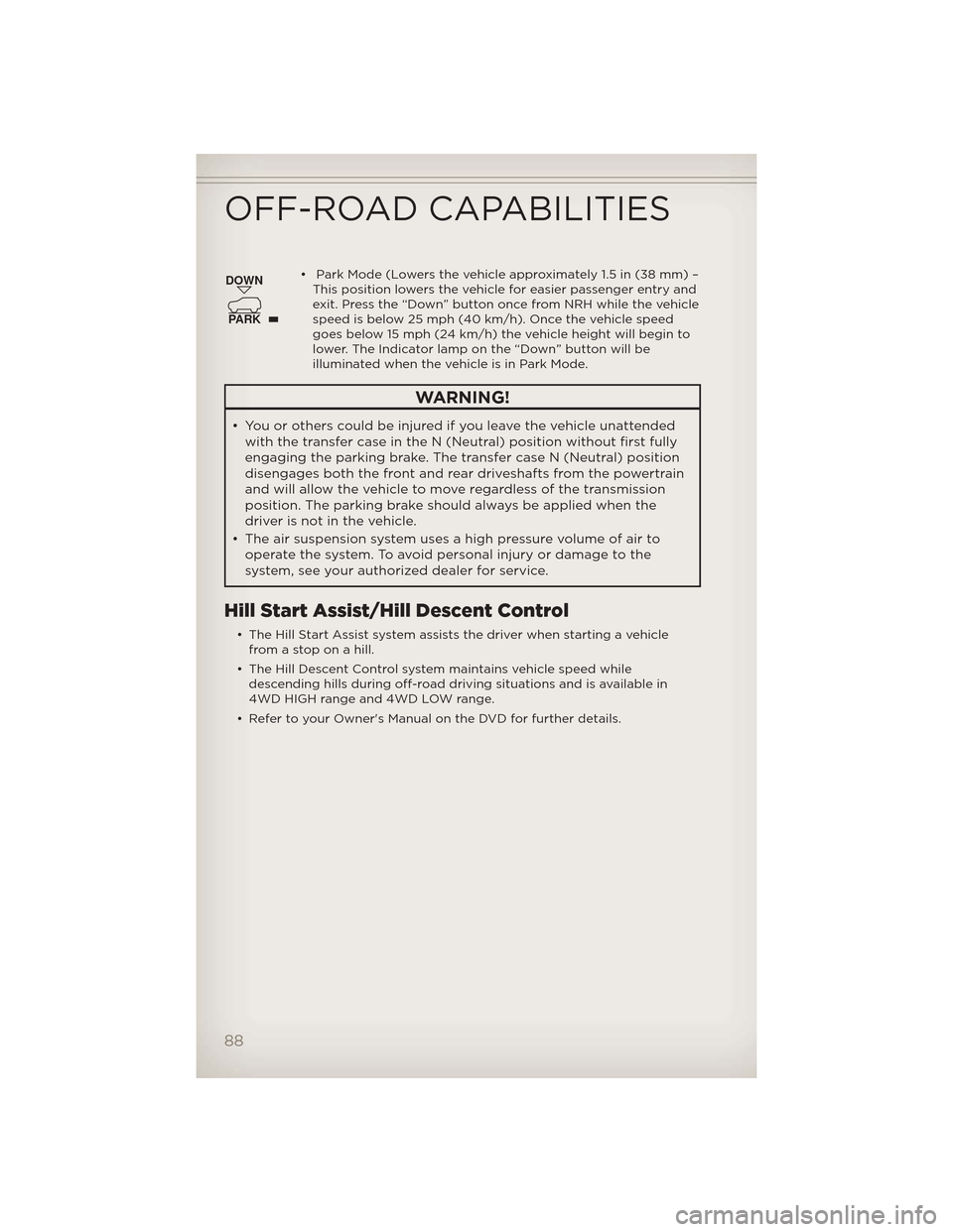
• Park Mode (Lowers the vehicle approximately 1.5 in (38 mm) –This position lowers the vehicle for easier passenger entry and
exit. Press the “Down” button once from NRH while the vehicle
speed is below 25 mph (40 km/h). Once the vehicle speed
goes below 15 mph (24 km/h) the vehicle height will begin to
lower. The Indicator lamp on the “Down” button will be
illuminated when the vehicle is in Park Mode.
WARNING!
• You or others could be injured if you leave the vehicle unattendedwith the transfer case in the N (Neutral) position without first fully
engaging the parking brake. The transfer case N (Neutral) position
disengages both the front and rear driveshafts from the powertrain
and will allow the vehicle to move regardless of the transmission
position. The parking brake should always be applied when the
driver is not in the vehicle.
• The air suspension system uses a high pressure volume of air to operate the system. To avoid personal injury or damage to the
system, see your authorized dealer for service.
Hill Start Assist/Hill Descent Control
• The Hill Start Assist system assists the driver when starting a vehiclefrom a stop on a hill.
• The Hill Descent Control system maintains vehicle speed while descending hills during off-road driving situations and is available in
4WD HIGH range and 4WD LOW range.
• Refer to your Owner's Manual on the DVD for further details.
DOWN
PARK
OFF-ROAD CAPABILITIES
88
Page 93 of 148
• For vehicles with Keyless Enter-N-Go™, remove the Keyless Enter-N-Go™button and use the Key Fob to complete this procedure.
• Turn the ignition switch to the ON/RUN position, but do not start the engine.
• Press and hold the brake pedal and shift the transmission into NEUTRAL.
• Using a ballpoint pen or similar object, press and hold the recessed transfer case N (Neutral) button for four seconds, until the light next to
the N symbol starts to blink, indicating shift in progress. The light will
stop blinking (stay on solid) when the shift to N (Neutral) is complete. A
“FOUR WHEEL DRIVE SYSTEM IN NEUTRAL” message will display on
the EVIC (Electronic Vehicle Information Center).
• Start the engine and shift the transmission into REVERSE.
• Release the brake pedal for five seconds and ensure that there is no vehicle movement.
• Turn the engine off and firmly apply the parking brake.
• Shift the transmission into PARK and remove the Key Fob.
• Attach the vehicle to the tow vehicle using a suitable tow bar and release the parking brake.
NOTE: Vehicles equipped with Quadra-Lift™ must be lowered to the “Park”
(lowest) level, and have automatic leveling disabled, before tying them down
(from the body) on a trailer or a flatbed truck. Refer to “Quadra-Lift™” in
“Off-Road Capabilities” for more information. If the vehicle cannot be
lowered to the “Park” level (for example, engine will not run), tie-downs must
be fastened to the axles (not the body). Failure to follow these instructions
may cause fault codes to be set and/or loss of proper tie-down tension.
CAUTION!
• Towing with the rear wheels on the ground will cause severe transmission damage. Damage from improper towing is not covered
under the New Vehicle Limited Warranty.
• Front or rear wheel lifts should not be used. Internal damage to the transmission or transfer case will occur if a front or rear wheel lift is
used when recreational towing.
• It is necessary to follow these steps to be certain that the transfer case is fully in NEUTRAL before recreational towing to prevent
damage to internal parts.
UTILITY
91
Page 94 of 148
WARNING!
You or others could be injured if you leave the vehicle unattended
with the transfer case in the NEUTRAL position without first fully
engaging the parking brake. The transfer case NEUTRAL position
disengages both the front and rear driveshafts from the powertrain
and will allow the vehicle to move even if the transmission is in PARK.
The parking brake should always beapplied when the driver is not in
the vehicle.
UTILITY
92
Page 100 of 148
• Your vehicle has also been equipped with a TPMS malfunction indicatorto indicate when the system is not operating properly. The TPMS
malfunction indicator is combined with the low tire pressure telltale.
When the system detects a malfunction, the telltale will flash for
approximately one minute and then remain continuously illuminated. This
sequence will continue each time the vehicle is restarted as long as the
malfunction exists.
• When the malfunction indicator is illuminated, the system may not be able to detect or signal low tire pressure as intended. TPMS malfunctions
may occur for a variety of reasons, including the installation of
replacement or alternate tires or wheels on the vehicle that prevent the
TPMS from functioning properly. Always check the TPMS malfunction
telltale after replacing one or more tires or wheels on your vehicle, to
ensure that the replacement or alternate tires and wheels allow the TPMS
to continue to function properly.
NOTE: Tire pressures change by approximately 1 psi (7 kPa) per 12° F (7° C)
of air temperature change. Keep this in mind when checking tire pressure
inside a garage, especially in the Winter. Example: If garage temperature is
68°F (20°C) and the outside temperature is 32°F (0°C), then the cold tire
inflation pressure should be increased by 3 psi (21 kPa), which equals 1 psi
(7 kPa) for every 12°F (7°C) for this outside temperature condition.
CAUTION!
The TPMS has been optimized for the original equipment tires and
wheels. TPMS pressures and warning have been established for the
tire size equipped on your vehicle. Undesirable system operation or
sensor damage may result when using replacement equipment that is
not of the same size, type, and/or style. Aftermarket wheels can cause
sensor damage. Do not use tire sealant from a can, or balance beads if
your vehicle is equipped with a TPMS, as damage to the sensors may
result.
BRAKE- Brake Warning Light
• The Brake Warning light illuminates when there is either a system malfunction or the parking brake is applied. If the light is on and the
parking brake is not applied, it indicates a possible brake hydraulic
malfunction, brake booster problem or an Anti-Lock Brake System
problem.
• Please have your vehicle serviced immediately.
WARNING!
Driving a vehicle with the red brake light on is dangerous. Part of the
brake system may have failed. It will take longer to stop the vehicle.
You could have a collision. Have the vehicle checked immediately.
WHAT TO DO IN EMERGENCIES
98
Page 106 of 148
Preparations For Jacking
1. Park the vehicle on a firm, level surface. Avoid ice or slippery surfaces.
2. Turn on the Hazard Warning flasher.
3. Set the parking brake.
4. Place the shift lever into PARK.
5. Turn the ignition OFF.
6. For vehicle equipped with Quadra-Lift® refer to “Quadra-Lift — IfEquipped” in “Starting And Operating” on the DVD for further
information on disabling automatic leveling.
Block both the front and rear of the
wheel diagonally opposite of the
jacking position. For example, if
changing the right front tire, block the
left rear wheel.
NOTE:Passengers should not remain
in the vehicle when the vehicle is
being jacked.
Jacking Instructions
1. Remove the spare tire, jack, and tools from storage.
2. Loosen (but do not remove) the wheel lug nuts by turning them to
the left, one turn, while the wheel
is still on the ground.
3. Assemble the jack and jacking tools.
WHAT TO DO IN EMERGENCIES
104
Page 109 of 148
Road Tire Installation
1. Mount the road tire on the axle.
2. Install the remaining lug nuts with the cone shaped end of the nuttoward the wheel. Lightly tighten the lug nuts.
3. Lower the vehicle to the ground by turning the jack handle counterclockwise.
4. Finish tightening the lug nuts. Push down on the wrench while at the end of the handle for increased leverage. Tighten the lug nuts in a star
pattern until each nut has been tightened twice. The correct tightness of
each lug nut is 110 ft/lbs (150 N·m). If in doubt about the correct
tightness, have them checked with a torque wrench by your authorized
dealer or service station.
5. After 25 miles (40 km) check the lug nut torque with a torque wrench to ensure that all lug nuts are properly seated against the wheel.
CAUTION!
• Do not attempt to raise the vehicle by jacking on locations otherthan those indicated in the Jacking Instructions for this vehicle.
• Be sure to mount the spare tire with the valve stem facing outward. The vehicle could be damaged if the spare tire is mounted
incorrectly.
WARNING!
• Do not attempt to change a tire on the side of the vehicle close tomoving traffic. Pull far enough off the road to avoid the danger of
being hit when operating the jack or changing the wheel.
• Being under a jacked-up vehicle is dangerous. The vehicle could slip off the jack and fall on you. You could be crushed. Never put any
part of your body under a vehicle that is on a jack. If you need to
get under a raised vehicle, take it to a service center where it can be
raised on a lift.
• Never start or run the engine while the vehicle is on a jack.
• The jack is designed to be used as a tool for changing tires only. The jack should not be used to lift the vehicle for service purposes. The
vehicle should be jacked on a firm level surface only. Avoid ice or
slippery areas.
• Always park on a firm, level surface as far from the edge of the
roadway as possible before raising the vehicle.
• Turn on the Hazard Warning flasher.
• Block the wheel diagonally opposite the wheel to be raised.
• Set the parking brake firmly and set an automatic transmission in PARK.
(Continued)
WHAT TO DO IN EMERGENCIES
107
Page 111 of 148
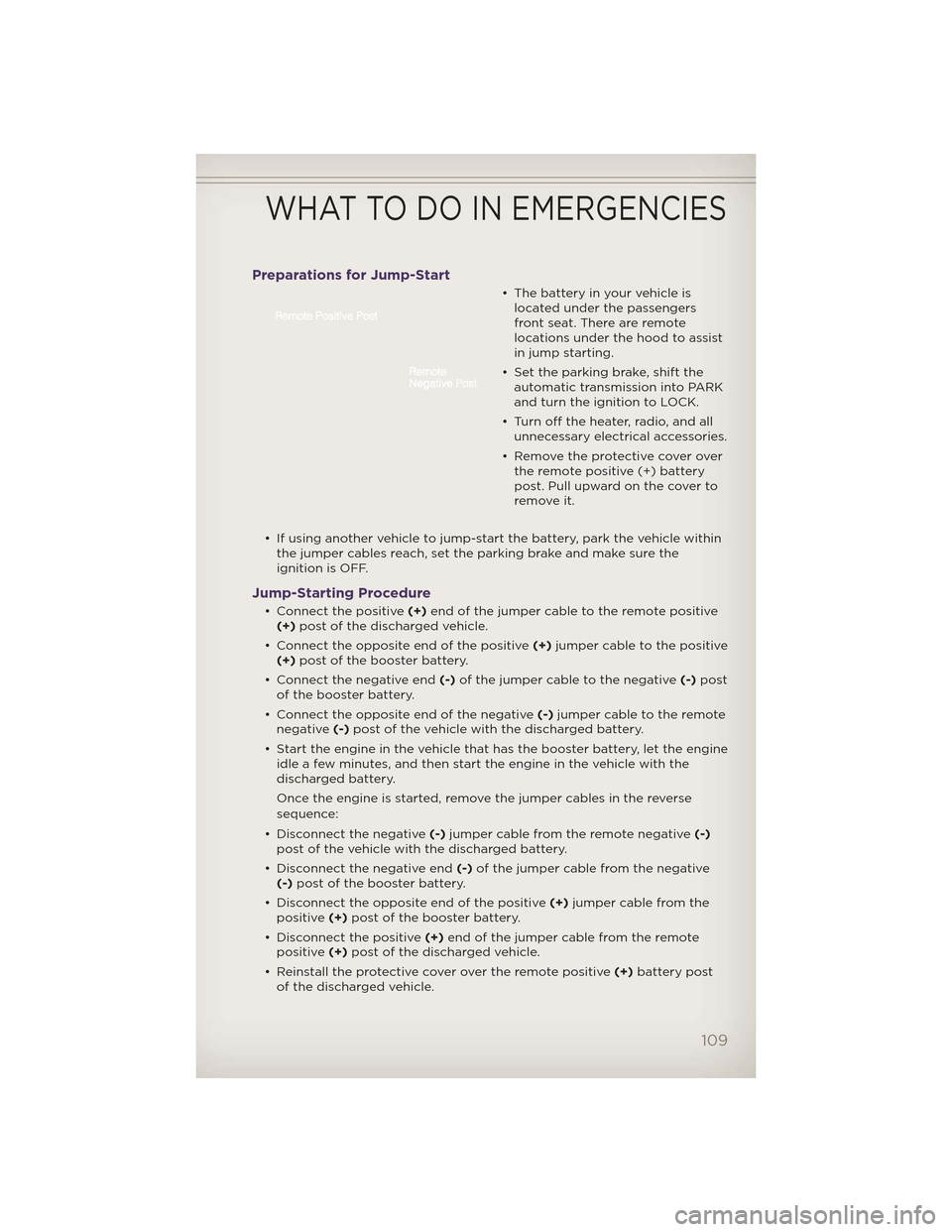
Preparations for Jump-Start
• The battery in your vehicle islocated under the passengers
front seat. There are remote
locations under the hood to assist
in jump starting.
• Set the parking brake, shift the automatic transmission into PARK
and turn the ignition to LOCK.
• Turn off the heater, radio, and all unnecessary electrical accessories.
• Remove the protective cover over the remote positive (+) battery
post. Pull upward on the cover to
remove it.
• If using another vehicle to jump-start the battery, park the vehicle within the jumper cables reach, set the parking brake and make sure the
ignition is OFF.
Jump-Starting Procedure
• Connect the positive (+)end of the jumper cable to the remote positive
(+) post of the discharged vehicle.
• Connect the opposite end of the positive (+)jumper cable to the positive
(+) post of the booster battery.
• Connect the negative end (-)of the jumper cable to the negative (-)post
of the booster battery.
• Connect the opposite end of the negative (-)jumper cable to the remote
negative (-)post of the vehicle with the discharged battery.
• Start the engine in the vehicle that has the booster battery, let the engine idle a few minutes, and then start the engine in the vehicle with the
discharged battery.
Once the engine is started, remove the jumper cables in the reverse
sequence:
• Disconnect the negative (-)jumper cable from the remote negative (-)
post of the vehicle with the discharged battery.
• Disconnect the negative end (-)of the jumper cable from the negative
(-) post of the booster battery.
• Disconnect the opposite end of the positive (+)jumper cable from the
positive (+)post of the booster battery.
• Disconnect the positive (+)end of the jumper cable from the remote
positive (+)post of the discharged vehicle.
• Reinstall the protective cover over the remote positive (+)battery post
of the discharged vehicle.
WHAT TO DO IN EMERGENCIES
109