spare tire JEEP GRAND CHEROKEE 2012 WK2 / 4.G User Guide
[x] Cancel search | Manufacturer: JEEP, Model Year: 2012, Model line: GRAND CHEROKEE, Model: JEEP GRAND CHEROKEE 2012 WK2 / 4.GPages: 148, PDF Size: 5.91 MB
Page 89 of 148
• The Quadra-Lift™ air suspension system uses a lifting and loweringpattern which keeps the headlights from shining into oncoming traffic.
When raising the vehicle, the rear of the vehicle will move up first and
then the front. When lowering the vehicle, the front will move down first
and then the rear.
• After the engine is turned off, you may notice that the air suspension system operates briefly. This is normal. The system is correcting the
position of the vehicle.
• To assist with changing a spare tire, the Quadra-Lift™ air suspension system has a feature which allows the automatic leveling to be disabled.
Press and hold both the “Up” and “Down” buttons simultaneously
between 5 and 10 seconds; a message will appear in the EVIC stating
leveling has been disabled immediately after both buttons have been
released. Driving the vehicle over 5 mph (8 km/h) will return the air
suspension to normal operation.
• An audible chime will be heard whenever a system error has been detected.
Operation • Pressing the “Up” or “Down” button once will move the suspension one position higher or lower from the current position, assuming all
conditions are met (i.e., engine running and all doors and liftgate closed).
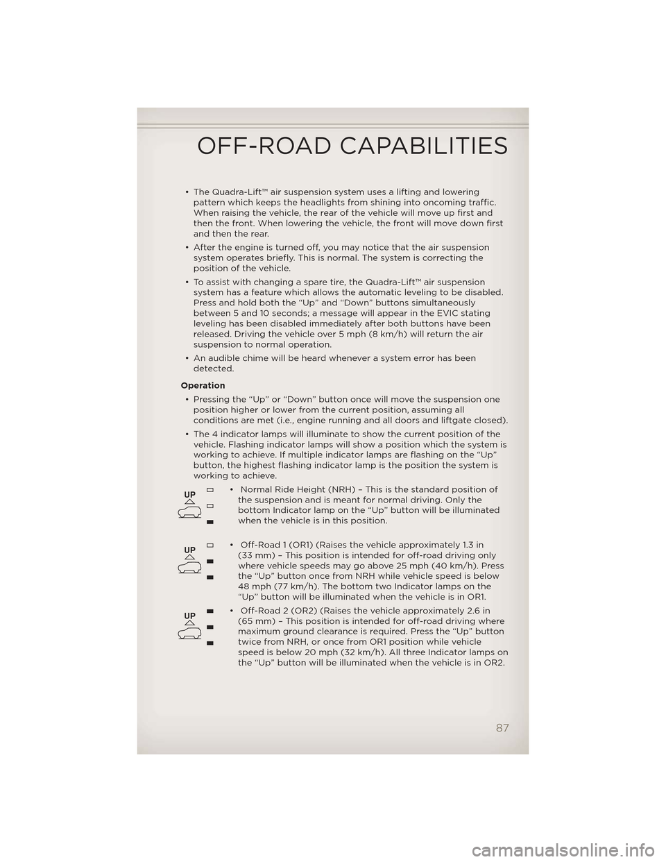
• The 4 indicator lamps will illuminate to show the current position of the vehicle. Flashing indicator lamps will show a position which the system is
working to achieve. If multiple indicator lamps are flashing on the “Up”
button, the highest flashing indicator lamp is the position the system is
working to achieve.
• Normal Ride Height (NRH) – This is the standard position ofthe suspension and is meant for normal driving. Only the
bottom Indicator lamp on the “Up” button will be illuminated
when the vehicle is in this position.
• Off-Road 1 (OR1) (Raises the vehicle approximately 1.3 in (33 mm) – This position is intended for off-road driving only
where vehicle speeds may go above 25 mph (40 km/h). Press
the “Up” button once from NRH while vehicle speed is below
48 mph (77 km/h). The bottom two Indicator lamps on the
“Up” button will be illuminated when the vehicle is in OR1.
• Off-Road 2 (OR2) (Raises the vehicle approximately 2.6 in (65 mm) – This position is intended for off-road driving where
maximum ground clearance is required. Press the “Up” button
twice from NRH, or once from OR1 position while vehicle
speed is below 20 mph (32 km/h). All three Indicator lamps on
the “Up” button will be illuminated when the vehicle is in OR2.
UP
UP
UP
OFF-ROAD CAPABILITIES
87
Page 91 of 148
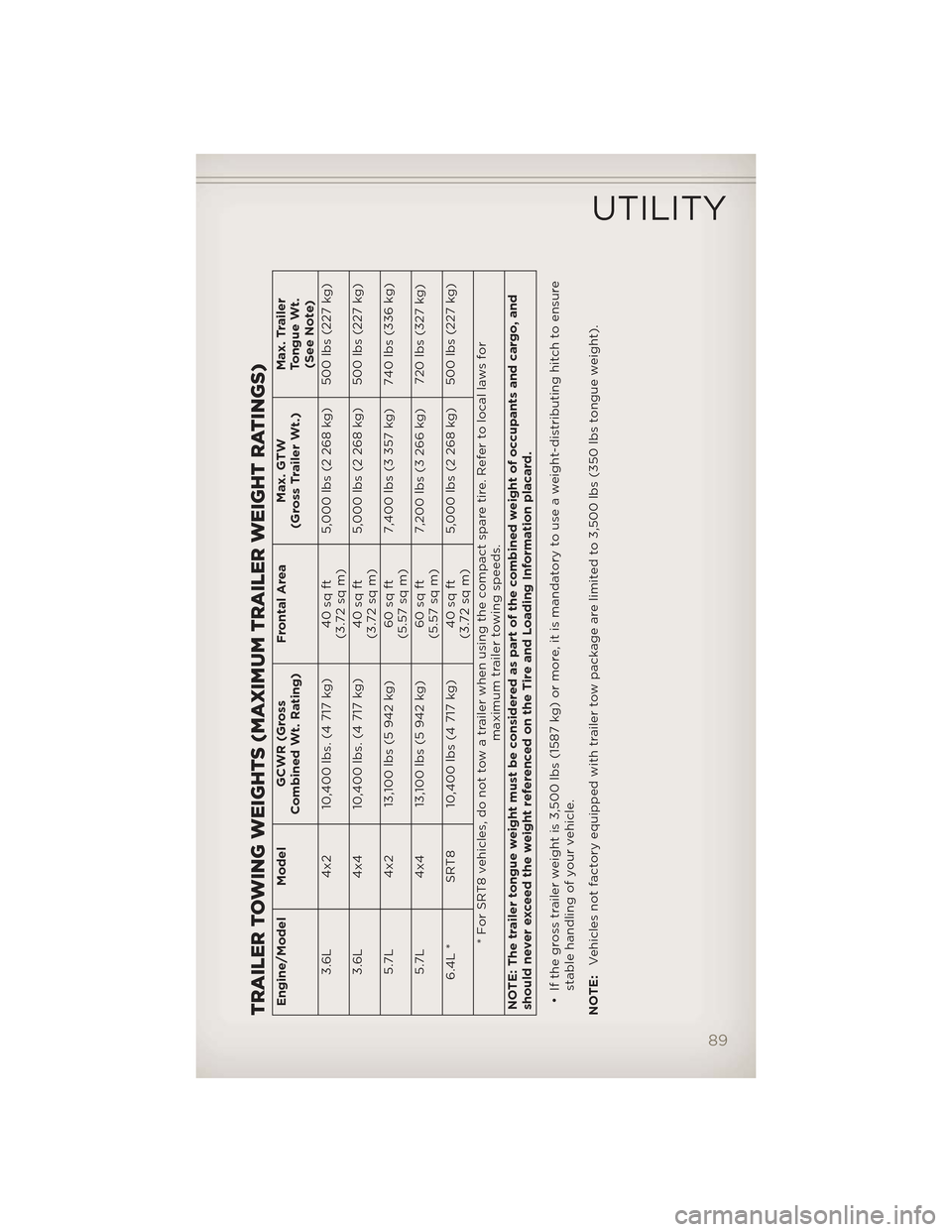
TRAILER TOWING WEIGHTS (MAXIMUM TRAILER WEIGHT RATINGS)Engine/Model ModelGCWR (Gross
Combined Wt. Rating) Frontal Area
Max. GTW
(Gross Trailer Wt.) Max. Trailer
Tongue Wt.
(See Note)
3.6L 4x2 10,400 lbs. (4 717 kg) 40 sq ft
(3.72 sq m)5,000 lbs (2 268 kg) 500 lbs (227 kg)
3.6L 4x4 10,400 lbs. (4 717 kg) 40 sq ft
(3.72 sq m)5,000 lbs (2 268 kg) 500 lbs (227 kg)
5.7L 4x2 13,100 lbs (5 942 kg) 60 sq ft
(5.57 sq m)7,400 lbs (3 357 kg) 740 lbs (336 kg)
5.7L 4x4 13,100 lbs (5 942 kg) 60 sq ft
(5.57 sq m)7,200 lbs (3 266 kg) 720 lbs (327 kg)
6.4L * SRT8 10,400 lbs (4 717 kg) 40 sq ft (3.72 sq m)5,000 lbs (2 268 kg) 500 lbs (227 kg)
* For SRT8 vehicles, do not tow a trailer when using the compact spare tire. Refer to local laws for maximum trailer towing speeds.
NOTE: The trailer tongue weight must be considered as part of the combined weight of occupants and cargo, and
should never exceed the weight referenced on the Tire and Loading Information placard.
• If the gross trailer weight is 3,500 lbs (1587 kg) or more, it is mandatory to use a weight-distributing hitch to ensure stable handling of your vehicle.
NOTE: Vehicles not factory equipped with trailer tow package are limited to 3,500 lbs (350 lbs tongue weight).
UTILITY
89
Page 99 of 148
24-HOUR TOWING ASSISTANCE
• Dial toll-free 1-800-521-2779 or 1-800-363-4869 for Canadian residents.
• Provide your name, vehicle identification number and license platenumber.
• Provide your location, including telephone number, from which you are calling.
• Briefly describe the nature of the problem and answer a few simple questions.
• You will be given the name of the service provider and an estimated time of arrival. If you feel you are in an “unsafe situation”, please let us know.
With your consent, we will contact local police or safety authorities.
INSTRUMENT CLUSTER WARNING LIGHTS
- Tire Pressure Monitoring System (TPMS) Light
• Each tire, including the spare (if provided), should be checked monthly,when cold and inflated to the inflation pressure recommended by the
vehicle manufacturer on the vehicle placard or tire inflation pressure
label. (If your vehicle has tires of a different size than the size indicated
on the vehicle placard or tire inflation pressure label, you should
determine the proper tire inflation pressure for those tires.)
• As an added safety feature, your vehicle has been equipped with a Tire Pressure Monitoring System (TPMS) that illuminates a low tire pressure
telltale when one or more of your tires is significantly under-inflated.
Accordingly, when the low tire pressure telltale illuminates, you should
stop and check your tires as soon as possible, and inflate them to the
proper pressure. Driving on a significantly under-inflated tire causes the
tire to overheat and can lead to tire failure. Under-inflation also reduces
fuel efficiency and tire tread life, and may affect the vehicle’s handling
and stopping ability.
• IF THE LIGHT STARTS FLASHING INDICATING A LOW TIRE PRESSURE,
ADJUST THE AIR PRESSURE IN THE LOW TIRE TO THE AIR PRESSURE
SHOWN ON THE VEHICLE PLACARD OR TIRE INFLATION PRESSURE
LABEL LOCATED ON THE DRIVER'S DOOR. NOTE: AFTER INFLATION,
THE VEHICLE MAY NEED TO BE DRIVEN FOR 20 MINUTES BEFORE
THE FLASHING LIGHT WILL TURN OFF.
• Please note that the TPMS is not a substitute for proper tire maintenance, and it is the driver’s responsibility to maintain correct tire
pressure, even if under-inflation has not reached the level to trigger
illumination of the TPMS low tire pressure telltale.
WHAT TO DO IN EMERGENCIES
97
Page 104 of 148

JACKING AND TIRE CHANGING
Run Flat Tires – SRT8 Only
• This vehicle is equipped with a compact spare along with run flat tires.Although the tires are designed with a “run flat” feature that allows the
vehicle to be driven approximately 50 miles (80 km) at 55 mph
(88 km/h). immediate service should be obtained.
NOTE:
The compact spare tire is to be used for rear wheel(s) only. For a flat
front tire, move the rear tire to the front and use the compact spare on the rear.
WARNING!
• Do not exceed 50 mph (80 km/h) if the “Tire Pressure Monitoring Telltale Light” is illuminated. Vehicle handling and braking may be
reduced. You could have a collision and be severely or fatally
injured.
• Do not tow a trailer when using the compact spare tire.
WHAT TO DO IN EMERGENCIES
102
Page 105 of 148

Jack Location
• The scissor-type jack and tire changing tools are located in rear cargoarea, below the load floor.
Spare Tire Stowage
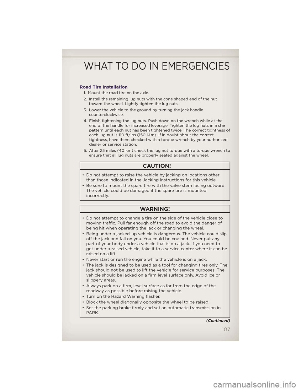
• The spare tire is stowed under the load floor in the rear cargo area and issecured to the body with a special wing nut.
WHAT TO DO IN EMERGENCIES
103
Page 106 of 148
Preparations For Jacking
1. Park the vehicle on a firm, level surface. Avoid ice or slippery surfaces.
2. Turn on the Hazard Warning flasher.
3. Set the parking brake.
4. Place the shift lever into PARK.
5. Turn the ignition OFF.
6. For vehicle equipped with Quadra-Lift® refer to “Quadra-Lift — IfEquipped” in “Starting And Operating” on the DVD for further
information on disabling automatic leveling.
Block both the front and rear of the
wheel diagonally opposite of the
jacking position. For example, if
changing the right front tire, block the
left rear wheel.
NOTE:Passengers should not remain
in the vehicle when the vehicle is
being jacked.
Jacking Instructions
1. Remove the spare tire, jack, and tools from storage.
2. Loosen (but do not remove) the wheel lug nuts by turning them to
the left, one turn, while the wheel
is still on the ground.
3. Assemble the jack and jacking tools.
WHAT TO DO IN EMERGENCIES
104
Page 108 of 148
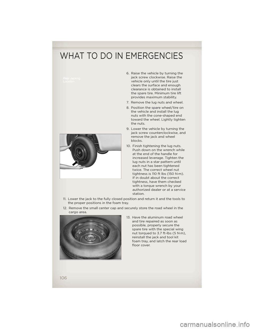
6. Raise the vehicle by turning thejack screw clockwise. Raise the
vehicle only until the tire just
clears the surface and enough
clearance is obtained to install
the spare tire. Minimum tire lift
provides maximum stability.
7. Remove the lug nuts and wheel.
8. Position the spare wheel/tire on the vehicle and install the lug
nuts with the cone-shaped end
toward the wheel. Lightly tighten
the nuts.
9. Lower the vehicle by turning the jack screw counterclockwise, and
remove the jack and wheel
blocks.
10. Finish tightening the lug nuts. Push down on the wrench while
at the end of the handle for
increased leverage. Tighten the
lug nuts in a star pattern until
each nut has been tightened
twice. The correct wheel nut
tightness is 110 ft lbs (150 N·m).
If in doubt about the correct
tightness, have them checked
with a torque wrench by your
authorized dealer or at a service
station.
11. Lower the jack to the fully closed position and return it and the tools to the proper positions in the foam tray.
12. Remove the small center cap and securely store the road wheel in the cargo area.
13. Have the aluminum road wheeland tire repaired as soon as
possible, properly secure the
spare tire with the special wing
nut torqued to 3.7 ft-lbs (5 N·m),
reinstall the jack and tool kit
foam tray, and latch the rear load
floor cover.
WHAT TO DO IN EMERGENCIES
106
Page 109 of 148
Road Tire Installation
1. Mount the road tire on the axle.
2. Install the remaining lug nuts with the cone shaped end of the nuttoward the wheel. Lightly tighten the lug nuts.
3. Lower the vehicle to the ground by turning the jack handle counterclockwise.
4. Finish tightening the lug nuts. Push down on the wrench while at the end of the handle for increased leverage. Tighten the lug nuts in a star
pattern until each nut has been tightened twice. The correct tightness of
each lug nut is 110 ft/lbs (150 N·m). If in doubt about the correct
tightness, have them checked with a torque wrench by your authorized
dealer or service station.
5. After 25 miles (40 km) check the lug nut torque with a torque wrench to ensure that all lug nuts are properly seated against the wheel.
CAUTION!
• Do not attempt to raise the vehicle by jacking on locations otherthan those indicated in the Jacking Instructions for this vehicle.
• Be sure to mount the spare tire with the valve stem facing outward. The vehicle could be damaged if the spare tire is mounted
incorrectly.
WARNING!
• Do not attempt to change a tire on the side of the vehicle close tomoving traffic. Pull far enough off the road to avoid the danger of
being hit when operating the jack or changing the wheel.
• Being under a jacked-up vehicle is dangerous. The vehicle could slip off the jack and fall on you. You could be crushed. Never put any
part of your body under a vehicle that is on a jack. If you need to
get under a raised vehicle, take it to a service center where it can be
raised on a lift.
• Never start or run the engine while the vehicle is on a jack.
• The jack is designed to be used as a tool for changing tires only. The jack should not be used to lift the vehicle for service purposes. The
vehicle should be jacked on a firm level surface only. Avoid ice or
slippery areas.
• Always park on a firm, level surface as far from the edge of the
roadway as possible before raising the vehicle.
• Turn on the Hazard Warning flasher.
• Block the wheel diagonally opposite the wheel to be raised.
• Set the parking brake firmly and set an automatic transmission in PARK.
(Continued)
WHAT TO DO IN EMERGENCIES
107
Page 110 of 148
WARNING!(Continued)
• Do not let anyone sit in the vehicle when it is on a jack.
• Do not get under the vehicle when it is on a jack.
• Only use the jack in the positions indicated and for lifting thisvehicle during a tire change.
• If working on or near a roadway, be extremely careful of motor traffic.
• To assure that spare tires, flat or inflated, are securely stowed, spares must be stowed with the valve stem facing the ground.
• Carefully follow these tire changing warnings to help prevent personal injury or damage to your vehicle:
• Raising the vehicle higher than necessary can make the vehicle less stable. It could slip off the jack and hurt someone near it. Raise the
vehicle only enough to remove the tire.
• To avoid the risk of forcing the vehicle off the jack, do not tighten the wheel nuts fully until the vehicle has been lowered. Failure to
follow this warning may result in personal injury.
• A loose tire or jack, thrown forward in a collision or hard stop could endanger the occupants of the vehicle. Always stow the jack parts
and the spare tire in the places provided. Have the deflated (flat)
tire repaired or replaced immediately.
BATTERY LOCATION
• The battery in your vehicle is located under the passenger's front seat. Remote battery posts are located on the right side of the engine
compartment for jump-starting.
JUMP-STARTING
• If your vehicle has a discharged battery it can be jump-started using aset of jumper cables and a battery in another vehicle or by using a
portable battery booster pack.
• Jump-starting can be dangerous if done improperly so please follow the procedures in this section carefully.
NOTE: When using a portable battery booster pack follow the
manufacturer’s operating instructions and precautions.
WHAT TO DO IN EMERGENCIES
108
Page 131 of 148
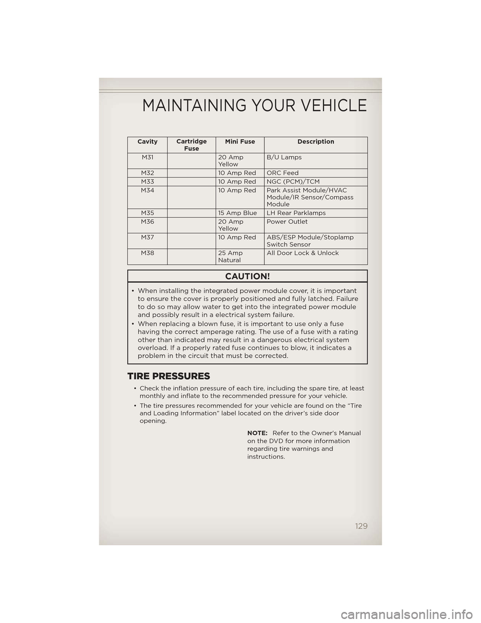
CavityCartridge
Fuse Mini Fuse Description
M31 20 Amp YellowB/U Lamps
M32 10 Amp Red ORC Feed
M33 10 Amp Red NGC (PCM)/TCM
M34 10 Amp Red Park Assist Module/HVAC Module/IR Sensor/Compass
Module
M35 15 Amp Blue LH Rear Parklamps
M36 20 Amp YellowPower Outlet
M37 10 Amp Red ABS/ESP Module/Stoplamp Switch Sensor
M38 25 Amp NaturalAll Door Lock & Unlock
CAUTION!
• When installing the integrated power module cover, it is important
to ensure the cover is properly positioned and fully latched. Failure
to do so may allow water to get into the integrated power module
and possibly result in a electrical system failure.
• When replacing a blown fuse, it is important to use only a fuse having the correct amperage rating. The use of a fuse with a rating
other than indicated may result in a dangerous electrical system
overload. If a properly rated fuse continues to blow, it indicates a
problem in the circuit that must be corrected.
TIRE PRESSURES
• Check the inflation pressure of each tire, including the spare tire, at leastmonthly and inflate to the recommended pressure for your vehicle.
• The tire pressures recommended for your vehicle are found on the “Tire and Loading Information” label located on the driver’s side door
opening.
NOTE:Refer to the Owner's Manual
on the DVD for more information
regarding tire warnings and
instructions.
MAINTAINING YOUR VEHICLE
129