engine JEEP GRAND CHEROKEE 2014 WK2 / 4.G Owner's Manual
[x] Cancel search | Manufacturer: JEEP, Model Year: 2014, Model line: GRAND CHEROKEE, Model: JEEP GRAND CHEROKEE 2014 WK2 / 4.GPages: 220, PDF Size: 6.12 MB
Page 135 of 220
Quadra-Trac II® /Quadra-Drive® II /Selec-Terrain™ Four-Wheel Drive Models
The transfer case must be shifted into NEUTRAL (N) and the transmission must be
in PARK for recreational towing. The NEUTRAL (N) selection button is adjacent to
the transfer case selector switch. Shifts into and out of transfer case NEUTRAL (N)
can take place with the selector switch in any mode position.
CAUTION!
• DO NOT dolly tow any 4WD vehicle. Internal damage to the transmission or
transfer case will occur if a dolly is used when recreational towing.
• Tow only in a forward direction. Towing this vehicle backwards can cause severe
damage to the transfer case.
• The transmission must be in PARK for recreational towing.
• Before recreational towing, perform the procedure outlined under “Shifting
into NEUTRAL (N)” to be certain that the transfer case is fully in NEUTRAL
(N). Otherwise, internal damage will result.
• Failure to follow these procedures can cause severe transmission and/or
transfer case damage. Damage from improper towing is not covered under the
New Vehicle Limited Warranty.
• Do not use a bumper-mounted clamp-on tow bar on your vehicle. The bumper
face bar will be damaged.
Shifting Into NEUTRAL (N)
Use the following procedure to prepare your vehicle for recreational towing:
1. Bring the vehicle to a complete stop, with the engine running.
2. Press and hold the brake pedal.
3. Shift the transmission into NEUTRAL.
4. If vehicle is equipped with Quadra-Lift™ air suspension, ensure the vehicle is set
to Normal Ride Height.
5. Using a ballpoint pen or similar object, press and hold the recessed transfer case
NEUTRAL (N) button (located by the selector switch) for four seconds. The light
behind the N symbol will blink, indicating shift in progress. The light will stop
blinking (stay on solid) when the shift to NEUTRAL (N) is complete. A “FOUR
WHEEL DRIVE SYSTEM IN NEUTRAL” message will display on the EVIC
(Electronic Vehicle Information Center).
6. After the shift is completed and the NEUTRAL (N) light stays on, release the
NEUTRAL (N) button.
7. Shift the transmission into REVERSE.
8. Release the brake pedal for five seconds and ensure that there is no vehicle
movement.
9. Shift the transmission back into NEUTRAL
UTILITY
133
Page 136 of 220
10. With the transmission and transfer case in NEUTRAL, press and hold the
ENGINE START/STOP button until the engine turns off. Turning the engine off
will automatically place the transmission in PARK.
11. Press the ENGINE STOP/START button again (without pressing the brake
pedal), if needed, to turn the ignition switch to the OFF position.
12. Firmly apply the parking brake.
13. Attach the vehicle to the tow vehicle using a suitable tow bar.
14. Release the parking brake.
NOTE:
• Steps 1 through 4 are requirements that must be met before pressing the
NEUTRAL (N) button, and must continue to be met until the shift has been
completed. If any of these requirements are not met before pressing the NEUTRAL
(N) button or are no longer met during the shift, then the NEUTRAL (N) indicator
light will flash continuously until all requirements are met or until the NEUTRAL
(N) button is released.
• The ignition switch must be in the ON/RUN position for a shift to take place and
for the position indicator lights to be operable. If the ignition switch is not in the
ON/RUN position, the shift will not take place and no position indicator lights will
be on or flashing.
• A flashing NEUTRAL (N) position indicator light indicates that shift requirements
have not been met.
• If the vehicle is equipped with Quadra-Lift™ air suspension, the engine should be
started and left running for a minimum of 60 seconds (with all the doors closed)
at least once every 24 hours. This process allows the air suspension to adjust the
vehicle’s ride height to compensate for temperature effects.
WARNING!
You or others could be injured or killed if you leave the vehicle unattended with the
transfer case in the NEUTRAL (N) position without first fully engaging the parking
brake. The transfer case NEUTRAL (N) position disengages both the front and rear
driveshafts from the powertrain and will allow the vehicle to move, even if the
transmission is in PARK. The parking brake should always be applied when the
driver is not in the vehicle.
CAUTION!
It is necessary to follow these steps to be certain that the transfer case is fully in
NEUTRAL (N) before recreational towing to prevent damage to internal parts.
UTILITY
134
Page 137 of 220
Shifting Out Of NEUTRAL (N)
Use the following procedure to prepare your vehicle for normal usage:
1. Bring the vehicle to a complete stop, leaving it connected to the tow vehicle.
2. Firmly apply the parking brake.
3. Start the engine.
4. Press and hold the brake pedal.
5. Shift the transmission into NEUTRAL.
6. Using a ballpoint pen or similar object, press and hold the recessed transfer case
NEUTRAL (N) button (located by the selector switch) for one second.
7. When the NEUTRAL (N) indicator light turns off, release the NEUTRAL (N)
button. After the NEUTRAL (N) button has been released, the transfer case will
shift to the position indicated by the selector switch.
8. Shift the transmission into PARK. Turn the engine OFF.
9. Release the brake pedal.
10. Disconnect vehicle from the tow vehicle.
11. Start the engine.
12. Press and hold the brake pedal.
13. Release the parking brake.
14. Shift the transmission into DRIVE, release the brake pedal, and check that the
vehicle operates normally.
NOTE:
• Steps 1 through 5 are requirements that must be met prior to pressing the
NEUTRAL (N) button, and must continue to be met until the shift has been
completed. If any of these requirements are not met prior to pressing the
NEUTRAL (N) button or are no longer met during the shift, the NEUTRAL (N)
indicator light will flash continuously until all requirements are met or until the
NEUTRAL (N) button is released.
• The ignition switch must be in the ON/RUN position for a shift to take place and
for the position indicator lights to be operable. If the ignition switch is not in the
ON/RUN position, the shift will not take place and no position indicator lights will
be on or flashing.
• A flashing NEUTRAL (N) position indicator light indicates that shift requirements
have not been met.
UTILITY
135
Page 138 of 220
PADDLE SHIFT MODE
Paddle Shift Mode is a driver-interactive transmission feature that offers manual gear
shifting to provide you with more control of the vehicle. Paddle Shift Mode allows you
to maximize engine braking, eliminate undesirable upshifts and downshifts, and
improve overall vehicle performance.
This system can also provide you with more control during passing, city driving, cold
slippery conditions, mountain driving, trailer towing, and many other situations.
Refer to the “Starting And Operating” section of your vehicle’s Owner’s Manual on
the DVD for further details.
Paddle Shift Mode Operation
When the shift lever is in the DRIVE position, the transmission will operate
automatically, shifting between the five available gears. To engage Paddle Shift
Mode, simply tap the shift lever to the right or left (+/-) while in the DRIVE position,
or tap one of the steering wheel-mounted shift paddles (+/-). Tapping (-) to enter
Paddle Shift Mode will downshift the transmission to the next lower gear, while using
(+) to enter Paddle Shift Mode will retain the current gear.
When Paddle Shift mode is active, the current transmission gear is displayed in the
instrument cluster. In Paddle Shift Mode, the transmission will shift up or down when
(+/-) is manually selected by the driver (using the shift lever, or the shift paddles),
unless an engine lugging or overspeed condition would result. It will remain in the
selected gear until another upshift or downshift is chosen, except as described
below:
• Normally, in Paddle Shift Mode, the transmission will automatically shift up when
maximum engine speed is reached. If, however, Paddle Shift Mode is engaged
while in SPORT mode, the transmission will remain in the selected gear even when
maximum engine speed is reached. The transmission will upshift only when
commanded by the driver.
• The transmission will automatically downshift as the vehicle slows (to prevent
engine lugging) and will display the current gear.
• The transmission will automatically downshift to first gear when coming to a stop.
After a stop, the driver should manually upshift (+) the transmission as the vehicle
is accelerated.
• You can start out in first or second gear. Tapping (+) (at a stop) will allow starting
in second gear. Starting out in second gear is helpful in snowy or icy conditions.
• If a requested downshift would cause the engine to over-speed, that shift will not
occur.
• The system will ignore attempts to upshift at too low of a vehicle speed.
SRT
136
Page 139 of 220
• Avoid using speed control when Paddle Shift mode is engaged.
• Transmission shifting will be more noticeable when Paddle Shift Mode is engaged.
• To disengage Paddle Shift Mode, hold the shift lever to the right or press and hold
the (+) shift paddle until “D” is once again displayed in the instrument cluster. You
can shift in or out of the Paddle Shift Mode at any time without taking your foot off
the accelerator pedal.
WARNING!
Do not downshift for additional engine braking on a slippery surface. The drive
wheels could lose their grip and the vehicle could skid, causing a collision or
personal injury.
SELEC-TRACK™
Selec-Track™ combines the capabilities of the vehicle control systems, along with
driver input, to provide the best performance for all terrains.
Rotate the mode control knob to select the following Selec-Track™ positions:
•Sport- Dry weather, on-road calibration. Performance based tuning that provides
a rear wheel drive feel but with improved handling and acceleration over a
two-wheel drive vehicle. The active suspension system will be in a semi firm mode,
and a green flag will light up in the instrument cluster.
•Snow- Tuning set for additional stability in inclement weather. Use on and off road
on loose traction surfaces such as snow.
•Auto- Fully automatic full time four-wheel drive operation can be used on and off
road. This position balances traction with seamless steering feel to provide
improved handling and acceleration over two-wheel drive vehicles.
•Track- This position offers track road calibration for use on high traction surfaces.
Driveline is maximized for traction. Some binding may be felt on less forgiving
surfaces.
•To w- Use this mode for towing. Vehicle suspension will go to Firm mode and peak
power will be limited in the engine controls.
SRT
137
Page 141 of 220
Digital Speedometer
When selected, this screen displays vehicle speed and records top speed.
WARNING!
Measurement of vehicle statistics with the Performance Features is intended for
off-highway or off-road use only and should not be done on any public roadways.
It is recommended that these features be used in a controlled environment and
within the limits of the law. The capabilities of the vehicle as measured by the
performance pages must never be exploited in a reckless or dangerous manner,
which can jeopardize the user’s safety or the safety of others. Only a safe,
attentive, and skillful driver can prevent accidents.
Uconnect® SRT Performance Features
WARNING!
Measurement of vehicle statistics with the Performance Features is intended for
off-highway or off-road use only and should not be done on any public roadways.
It is recommended that these features be used in a controlled environment and
within the limits of the law. The capabilities of the vehicle as measured by the
performance pages must never be exploited in a reckless or dangerous manner,
which can jeopardize the user’s safety or the safety of others. Only a safe,
attentive, and skillful driver can prevent accidents.
• To access the SRT Performance Features, press the “SRT & Apps” button on the
touchscreen then press the “SRT Performance” button on the touchscreen. Press
the UP or DOWN buttons on the touchscreen to cycle through the features. Press
the desired feature button to select that feature.
• The Performance Page includes the following menus:
•
Home•
Gauges 2
•
Timers•
Engine
•
G – Force•
Options
•
Gauges 1
Timers
0-60 mph (0-100 km/h), 1/8 Mile, 1/4 Mile
When selected, this screen displays the time it takes for the vehicle to go from 0 to
60 mph (0 to 100 km/h), 1/8 mile or 1/4 mile.
SRT
139
Page 142 of 220
Braking Distance
When selected, this screen displays the vehicle's braking distance and the speed at
which the brake pedal was depressed.
G-Force
When selected, this screen displays all four G-Force values (two lateral and two
longitudinal) as well as steering angle.
Gauges 1
• Oil Temperature
• Oil Pressure
• Battery Voltage
Gauges 2
• Coolant Temperature
• Transmission Temperature
• Intake Air Temperature
Engine
When selected, this screen displays miles per hour (mph), horsepower (hp), torque
(ft/lb), oil pressure (psi) and gear selector values.
Options
When selected, this screen allows you to choose a standard or custom display for your
SRT home page.
WARNING!
Measurement of vehicle statistics with the Performance Features is intended for
off-highway or off-road use only and should not be done on any public roadways.
It is recommended that these features be used in a controlled environment and
within the limits of the law. The capabilities of the vehicle as measured by the
performance pages must never be exploited in a reckless or dangerous manner,
which can jeopardize the user’s safety or the safety of others. Only a safe,
attentive, and skillful driver can prevent accidents.
SRT
140
Page 144 of 220
DIESEL ENGINE BREAK-IN RECOMMENDATIONS
The diesel engine does not require a break-in period due to its construction. Normal
operation is allowed, providing the following recommendations are followed:
• Warm up the engine before placing it under load.
• Do not operate the engine at idle for prolonged periods.
• Use the appropriate transmission gear to prevent engine lugging.
• Observe vehicle oil pressure and temperature indicators.
• Check the coolant and oil levels frequently.
• Vary throttle position at highway speeds when carrying or towing significant
weight.
NOTE:
Light duty operation such as light trailer towing or no load operation will extend the
time before the engine is at full efficiency. Reduced fuel economy and power may be
seen at this time.
The engine oil installed in the engine at the factory is a high-quality energy conserving
type lubricant. Oil changes should be consistent with anticipated climate conditions
under which vehicle operations will occur. NON-DETERGENT OR STRAIGHT MINERAL
OILS MUST NEVER BE USED.
DIESEL ENGINE STARTING PROCEDURES
Normal Starting Procedure
1. Apply the parking brake.
2. Ensure the shift lever is in the PARK position.
3. Press and hold the brake pedal while pressing the ENGINE START/STOP button
once.
4. The system will take over and attempt to start the vehicle. If the vehicle fails to
start, the starter will disengage automatically after 30 seconds.
5. If you wish to stop the cranking of the engine prior to the engine starting, press the
button again.
6. Check that the oil pressure warning light has turned off.
7. Release the parking brake.
NOTE:
A delay of the start-up can be as long as five seconds under very cold conditions. The
"Wait to Start" telltale will be illuminated during the pre-heat process and the start
will commence upon the telltale going out.
DIESEL
142
Page 145 of 220
CAUTION!
If the “Water in Fuel Indicator Light” remains on, DO NOT START the engine
before you drain the water from the fuel filters to avoid engine damage. Refer to
“Maintenance Procedures/Draining Fuel/Water Separator Filter” in “Maintaining
Your Vehicle” in your Diesel Supplement on the DVD for further information.
Extreme Cold Weather
• The engine block heater is a resistance heater installed in the water jacket of the
engine. It requires a 110–115 Volt AC electrical outlet with a grounded, three-wire
extension cord.
• Its use is recommended for environments that routinely fall below -10°F. It should
be used when the vehicle has not been running overnight or longer periods and
should be plugged in two hours prior to start. Its use is required for cold starts with
temperatures under -20°F.
• A 12 Volt heater built into the fuel filter housing aids in preventing fuel gelling. It
is controlled by a built-in thermostat.
• A Diesel Pre-Heat system both improves engine starting and reduces the amount
of white smoke generated by a warming engine.
NOTE:
The engine block heater cord is a factory installed option. If your vehicle is not
equipped, heater cords are available from your authorized MOPAR
®dealer.
Water In Fuel Message
If a Water In Fuel message orindicator appears in the cluster and a chime
sounds five times, the fuel/water separator will need to be drained immediately to
prevent engine damage.
Refer to “Draining Fuel Water Separator” in this guide for draining instructions or see
your dealer.
DIESEL
143
Page 146 of 220
DIESEL FUEL FILTERS/WATER SEPARATOR
Draining Fuel/Water Separator
If the “Water in Fuel” indicator light
is illuminated and an audible chime is
heard five times, you should stop the
engine and drain the water from the sepa-
rator.
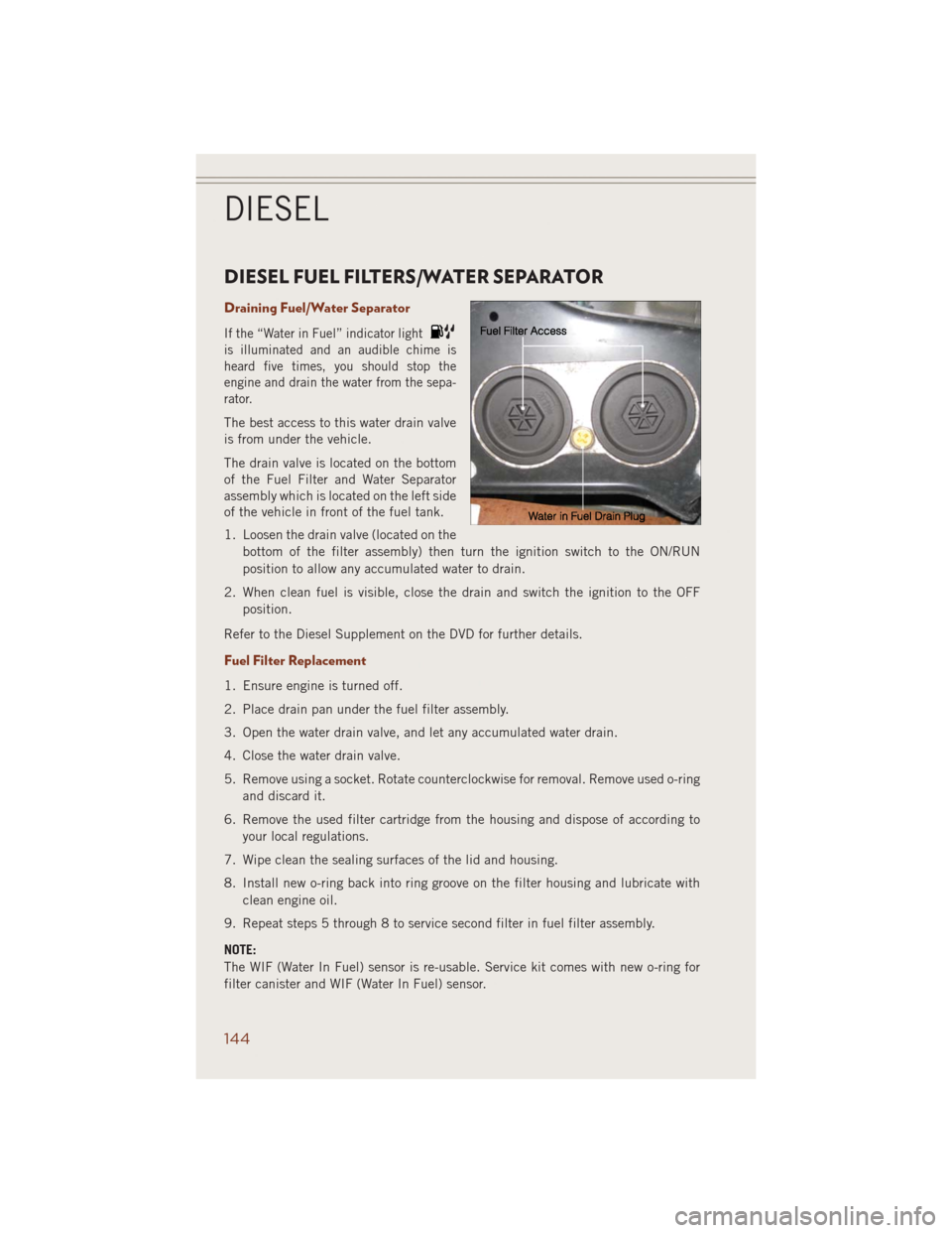
The best access to this water drain valve
is from under the vehicle.
The drain valve is located on the bottom
of the Fuel Filter and Water Separator
assembly which is located on the left side
of the vehicle in front of the fuel tank.
1. Loosen the drain valve (located on the
bottom of the filter assembly) then turn the ignition switch to the ON/RUN
position to allow any accumulated water to drain.
2. When clean fuel is visible, close the drain and switch the ignition to the OFF
position.
Refer to the Diesel Supplement on the DVD for further details.
Fuel Filter Replacement
1. Ensure engine is turned off.
2. Place drain pan under the fuel filter assembly.
3. Open the water drain valve, and let any accumulated water drain.
4. Close the water drain valve.
5. Remove using a socket. Rotate counterclockwise for removal. Remove used o-ring
and discard it.
6. Remove the used filter cartridge from the housing and dispose of according to
your local regulations.
7. Wipe clean the sealing surfaces of the lid and housing.
8. Install new o-ring back into ring groove on the filter housing and lubricate with
clean engine oil.
9. Repeat steps 5 through 8 to service second filter in fuel filter assembly.
NOTE:
The WIF (Water In Fuel) sensor is re-usable. Service kit comes with new o-ring for
filter canister and WIF (Water In Fuel) sensor.
DIESEL
144