flat tire JEEP GRAND CHEROKEE 2015 WK2 / 4.G User Guide
[x] Cancel search | Manufacturer: JEEP, Model Year: 2015, Model line: GRAND CHEROKEE, Model: JEEP GRAND CHEROKEE 2015 WK2 / 4.GPages: 717, PDF Size: 18.54 MB
Page 456 of 717
Air Suspension Modes
The Air Suspension system has multiple modes to protect
the system in unique situations:
Tire/Jack Mode
To assist with changing a spare tire, the air suspension
system has a feature which allows the automatic leveling
to be disabled. Refer to “Uconnect® Settings” in “Under-
standing Your Instrument Panel” for further information.
NOTE:This mode is intended to be enabled with engine
running.
Transport Mode
To assist with flat bed towing, the air suspension system
has a feature which will put the vehicle into Entry/Exit
height and disable the automatic load leveling system.
Refer to “Uconnect® Settings” in “Understanding Your
Instrument Panel” for further information.
NOTE:This mode is intended to be enabled with engine
running.
Wheel Alignment Mode
Before performing a wheel alignment this mode must be
enabled. Refer to “Uconnect® Settings” in “Understand-
ing Your Instrument Panel” for further information.
NOTE:This mode is intended to be enabled with engine
running.
If equipped with a touch screen radio all enabling/
disabling of air suspension features must be done
through the radio. Refer to “Uconnect® Settings” in
“Understanding Your Instrument Panel” for further in-
formation.
454 STARTING AND OPERATING
Page 475 of 717
In the event power assist is lost for any reason (i.e.,
repeated brake applications with the engine off) the
brakes will still function. However, the effort required to
brake the vehicle will be much greater than that required
with the power system operating.
ELECTRONIC BRAKE CONTROL SYSTEM
Your vehicle is equipped with an advanced electronic
brake control system that includes the Anti-Lock Brake
System (ABS), Traction Control System (TCS), Brake
Assist System (BAS), Electronic Roll Mitigation (ERM),
and Electronic Stability Control (ESC). All five of these
systems work together to enhance vehicle stability and
control in various driving conditions.
Also, your vehicle may be equipped with Trailer Sway
Control (TSC), Hill Start Assist (HSA), Ready Alert
Braking (RAB), Rain Brake Support (RBS) and, if it has
four-wheel drive with the MP 3023 two-speed transfer
case, Hill Descent Control (HDC), Selec Speed Control
(SSC).
Anti-Lock Brake System (ABS)
The Anti-Lock Brake System (ABS) is designed to aid the
driver in maintaining vehicle control under adverse
braking conditions. The system operates with a separate
computer to modulate hydraulic pressure to prevent
wheel lock-up and help avoid skidding on slippery
surfaces.
All vehicle wheels and tires must be the same size and
type, and tires must be properly inflated to produce
accurate signals for the computer.
5
STARTING AND OPERATING 473
Page 476 of 717
WARNING!
Significant over or under-inflation of tires, or mixing
sizes of tires or wheels on the vehicle can lead to loss
of braking effectiveness.
The Anti-Lock Brake System conducts a low speed self-
test at about 12 mph (20 km/h). If for any reason your
foot is on the brake when the vehicle reaches 12 mph
(20 km/h), this check will be delayed until 25 mph
(40 km/h).
The Anti-Lock Brake System pump motor runs during
the self-test, and during an ABS stop, to provide the
regulated hydraulic pressure. The motor pump makes a
low humming noise during operation; this is normal.
WARNING!
•Pumping of the Anti-Lock Brakes will diminish
their effectiveness and may lead to a collision.
Pumping makes the stopping distance longer. Just
press firmly on your brake pedal when you need to
slow down or stop.
•The Anti-Lock Brake System (ABS) cannot prevent
the natural laws of physics from acting on the
vehicle, nor can they increase braking or steering
efficiency beyond that afforded by the condition of
the vehicle brakes and tires or the traction afforded.
•The ABS cannot prevent collisions, including those
resulting from excessive speed in turns, following
another vehicle too closely, or hydroplaning.
•The capabilities of an ABS-equipped vehicle must
never be exploited in a reckless or dangerous
manner which could jeopardize the user’s safety or
the safety of others.
474 STARTING AND OPERATING
Page 498 of 717
EXAMPLE:
H= Speed Symbol
– A symbol indicating the range of speeds at which a tire can carry a load corresponding to
its load index under certain operating conditions
– The maximum speed corresponding to the speed symbol should only be achieved under
specified operating conditions (i.e., tire pressure, vehicle loading, road conditions, and
posted speed limits)
Load Identification:
Absence of the following load identification symbols on the sidewall of the tire indicates a Standard Load (SL)
tire:
•XL= Extra load (or reinforced) tire, or
•LL= Light load tire or
•C, D, E, F, G= Load range associated with the maximum load a tire can carry at a specified pressure
Maximum Load– Maximum load indicates the maximum load this tire is designed to carry
Maximum Pressure– Maximum pressure indicates the maximum permissible cold tire inflation pressure for this
tire
496 STARTING AND OPERATING
Page 500 of 717
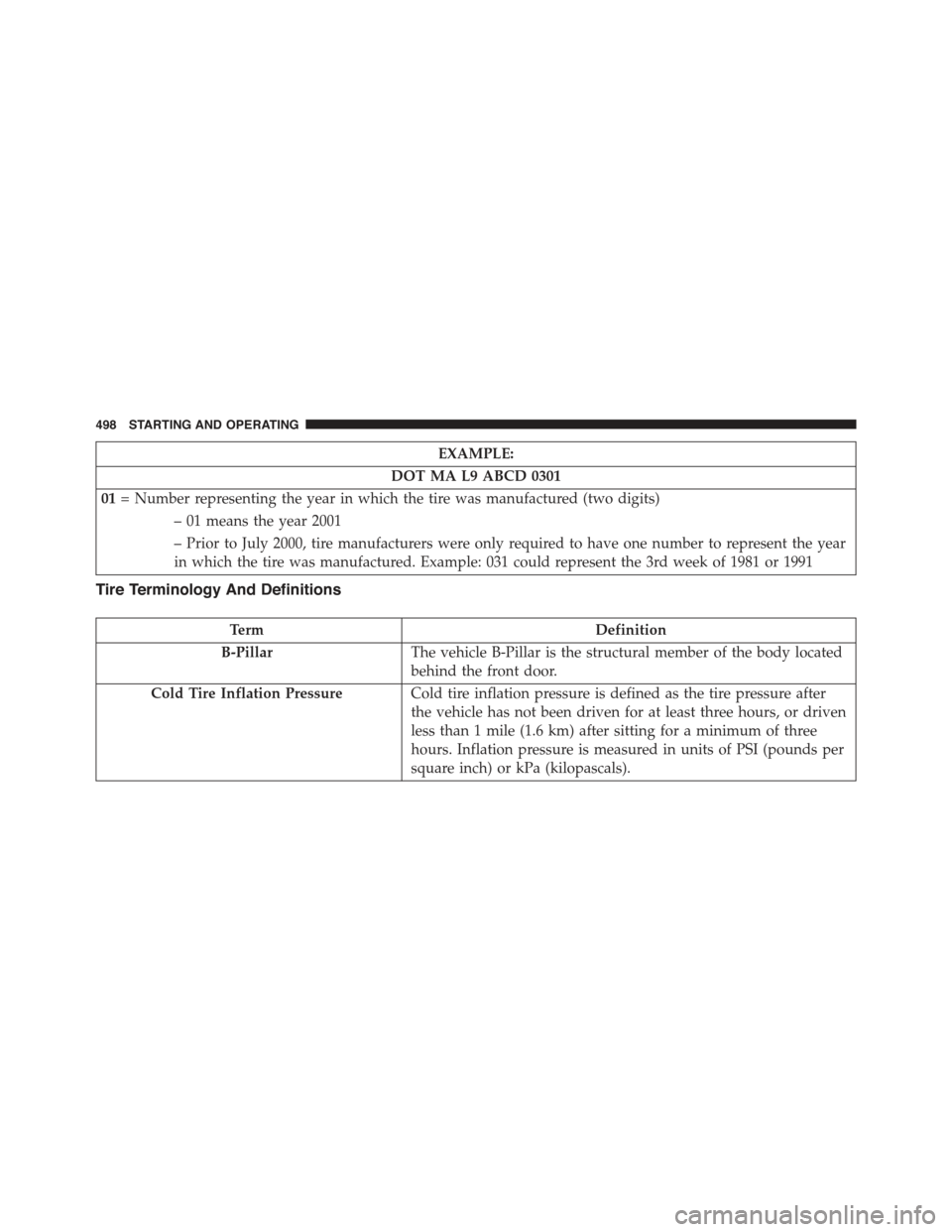
EXAMPLE:
DOT MA L9 ABCD 0301
01= Number representing the year in which the tire was manufactured (two digits)
– 01 means the year 2001
– Prior to July 2000, tire manufacturers were only required to have one number to represent the year
in which the tire was manufactured. Example: 031 could represent the 3rd week of 1981 or 1991
Tire Terminology And Definitions
TermDefinition
B-PillarThe vehicle B-Pillar is the structural member of the body located
behind the front door.
Cold Tire Inflation PressureCold tire inflation pressure is defined as the tire pressure after
the vehicle has not been driven for at least three hours, or driven
less than 1 mile (1.6 km) after sitting for a minimum of three
hours. Inflation pressure is measured in units of PSI (pounds per
square inch) or kPa (kilopascals).
498 STARTING AND OPERATING
Page 501 of 717
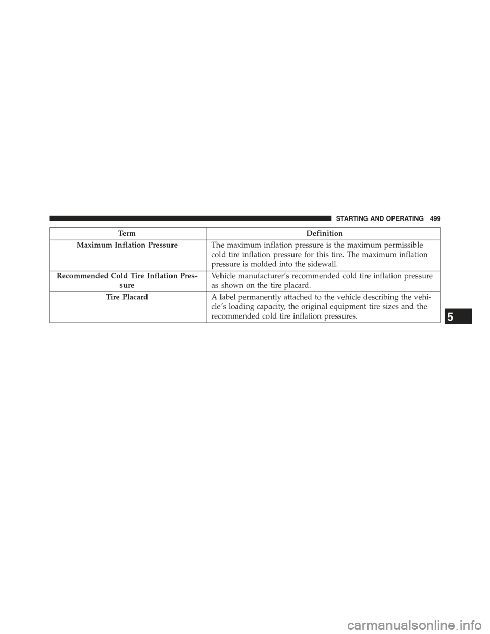
TermDefinition
Maximum Inflation PressureThe maximum inflation pressure is the maximum permissible
cold tire inflation pressure for this tire. The maximum inflation
pressure is molded into the sidewall.
Recommended Cold Tire Inflation Pres-
sure
Vehicle manufacturer’s recommended cold tire inflation pressure
as shown on the tire placard.
Tire PlacardA label permanently attached to the vehicle describing the vehi-
cle’s loading capacity, the original equipment tire sizes and the
recommended cold tire inflation pressures.5
STARTING AND OPERATING 499
Page 502 of 717
Tire Loading And Tire Pressure
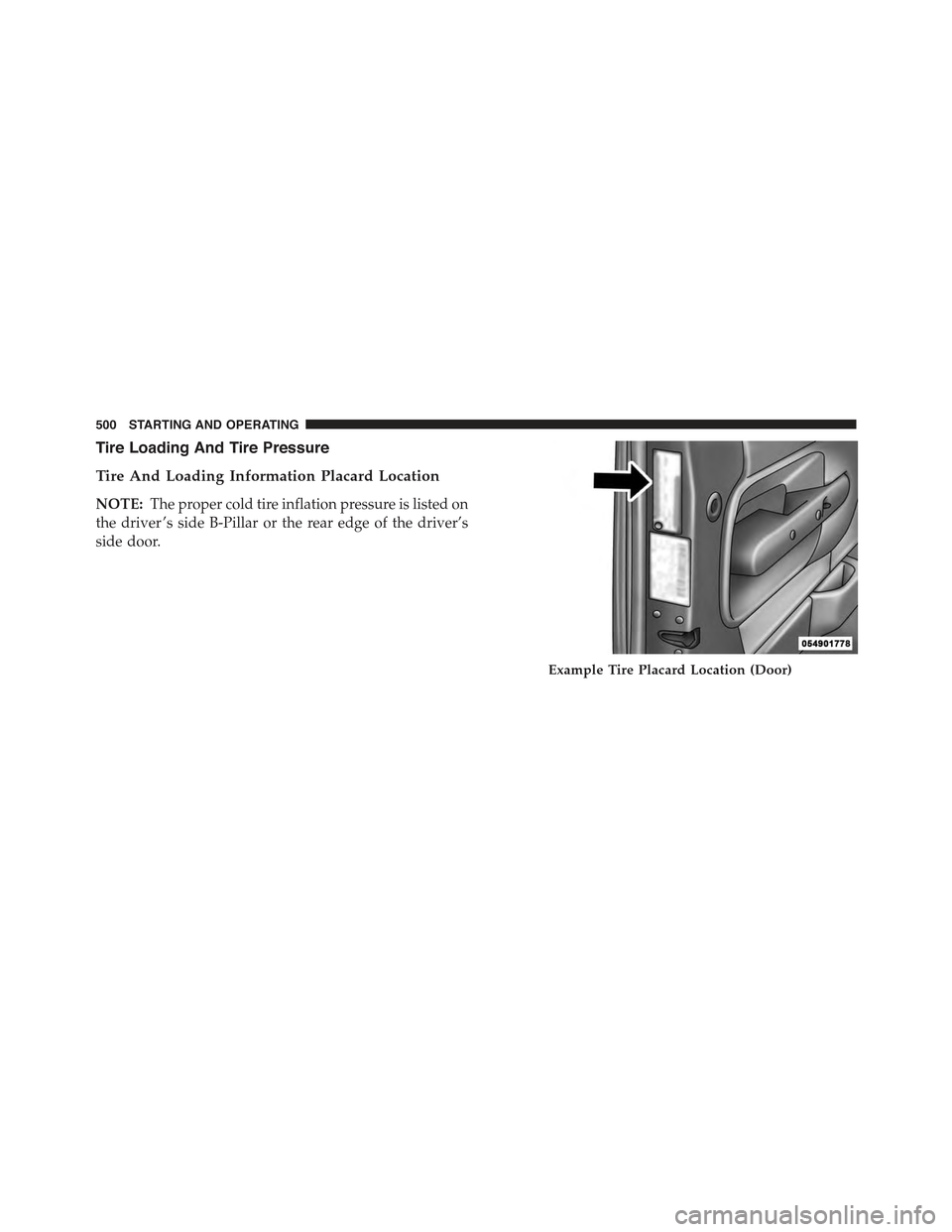
Tire And Loading Information Placard Location
NOTE:The proper cold tire inflation pressure is listed on
the driver ’s side B-Pillar or the rear edge of the driver’s
side door.
Example Tire Placard Location (Door)
500 STARTING AND OPERATING
Page 504 of 717
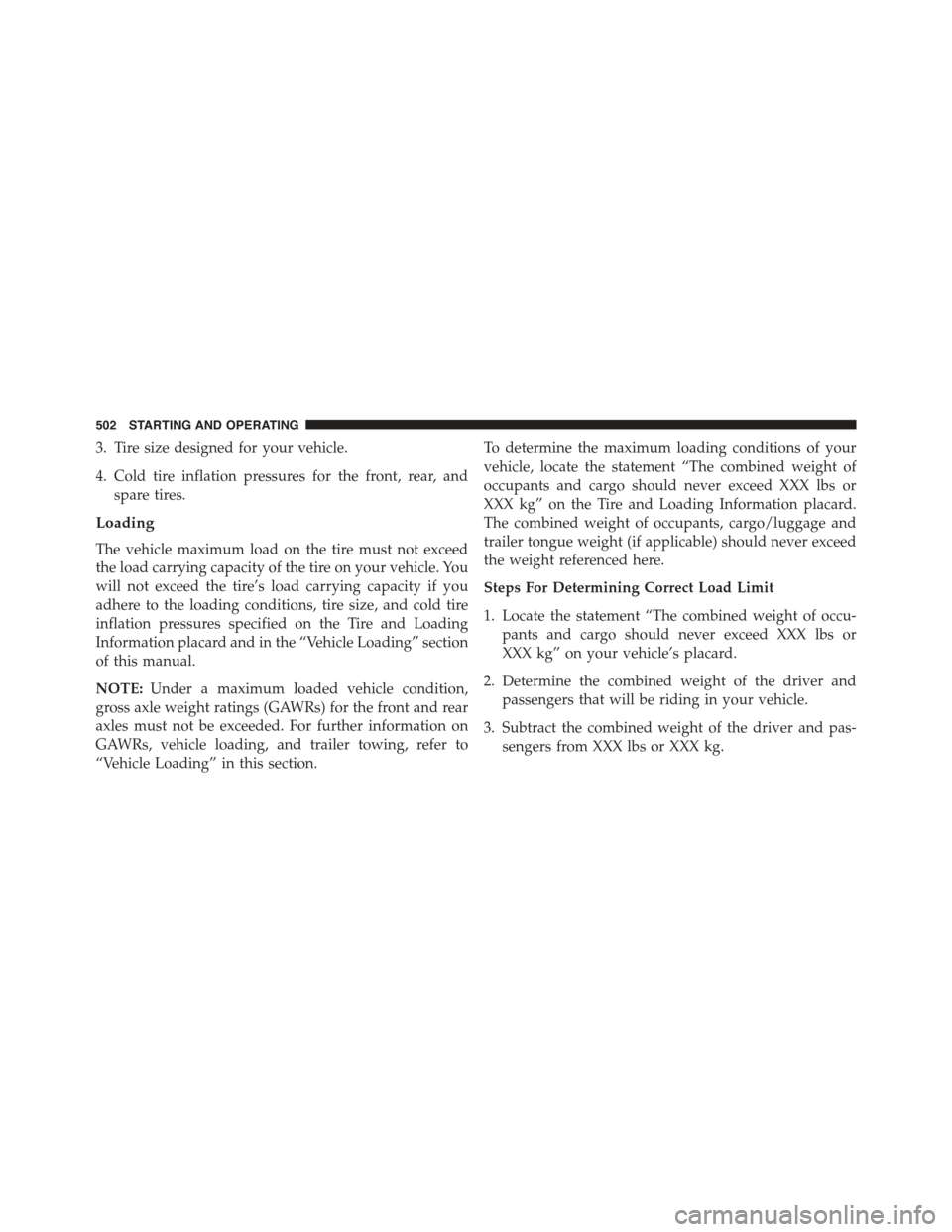
3. Tire size designed for your vehicle.
4. Cold tire inflation pressures for the front, rear, and
spare tires.
Loading
The vehicle maximum load on the tire must not exceed
the load carrying capacity of the tire on your vehicle. You
will not exceed the tire’s load carrying capacity if you
adhere to the loading conditions, tire size, and cold tire
inflation pressures specified on the Tire and Loading
Information placard and in the “Vehicle Loading” section
of this manual.
NOTE:Under a maximum loaded vehicle condition,
gross axle weight ratings (GAWRs) for the front and rear
axles must not be exceeded. For further information on
GAWRs, vehicle loading, and trailer towing, refer to
“Vehicle Loading” in this section.
To determine the maximum loading conditions of your
vehicle, locate the statement “The combined weight of
occupants and cargo should never exceed XXX lbs or
XXX kg” on the Tire and Loading Information placard.
The combined weight of occupants, cargo/luggage and
trailer tongue weight (if applicable) should never exceed
the weight referenced here.
Steps For Determining Correct Load Limit
1. Locate the statement “The combined weight of occu-
pants and cargo should never exceed XXX lbs or
XXX kg” on your vehicle’s placard.
2. Determine the combined weight of the driver and
passengers that will be riding in your vehicle.
3. Subtract the combined weight of the driver and pas-
sengers from XXX lbs or XXX kg.
502 STARTING AND OPERATING
Page 507 of 717
WARNING!
Overloading of your tires is dangerous. Overloading
can cause tire failure, affect vehicle handling, and
increase your stopping distance. Use tires of the
recommended load capacity for your vehicle. Never
overload them.
TIRES — GENERAL INFORMATION
Tire Pressure
Proper tire inflation pressure is essential to the safe and
satisfactory operation of your vehicle. Four primary areas
are affected by improper tire pressure:
•Safety and Vehicle Stability
•Economy
•Tread Wear
•Ride Comfort
Safety
WARNING!
•Improperly inflated tires are dangerous and can
cause collisions.
•Under-inflation increases tire flexing and can re-
sult in over-heating and tire failure.
•Over-inflation reduces a tire’s ability to cushion
shock. Objects on the road and chuckholes can
cause damage that result in tire failure.
•Over-inflated or under-inflated tires can affect ve-
hicle handling and can fail suddenly, resulting in
loss of vehicle control.
•Unequal tire pressures can cause steering prob-
lems. You could lose control of your vehicle.
(Continued)
5
STARTING AND OPERATING 505
Page 508 of 717
WARNING!(Continued)
•Unequal tire pressures from one side of the vehicle
to the other can cause the vehicle to drift to the
right or left.
•Always drive with each tire inflated to the recom-
mended cold tire inflation pressure.
Both under-inflation and over-inflation affect the stability
of the vehicle and can produce a feeling of sluggish
response or over responsiveness in the steering.
NOTE:
•Unequal tire pressures from side to side may cause
erratic and unpredictable steering response.
•Unequal tire pressure from side to side may cause the
vehicle to drift left or right.
Economy
Under-inflated tires will increase tire rolling resistance
resulting in higher fuel consumption.
Tread Wear
Improper cold tire inflation pressures can cause abnor-
mal wear patterns and reduced tread life, resulting in the
need for earlier tire replacement.
Ride Comfort And Vehicle Stability
Proper tire inflation contributes to a comfortable ride.
Over-inflation produces a jarring and uncomfortable
ride.
Tire Inflation Pressures
The proper cold tire inflation pressure is listed on the
driver’s side B-Pillar or rear edge of the driver’s side
door.
506 STARTING AND OPERATING