air suspension JEEP GRAND CHEROKEE 2015 WK2 / 4.G SRT Owners Manual
[x] Cancel search | Manufacturer: JEEP, Model Year: 2015, Model line: GRAND CHEROKEE, Model: JEEP GRAND CHEROKEE 2015 WK2 / 4.GPages: 636, PDF Size: 5.35 MB
Page 300 of 636
6. Selectable Information (Compass, Temp, Range to
Empty, Trip A, Trip B, Average Fuel Economy, Current
Fuel Economy)
7. Air Suspension Status — If Equipped
8. 4WD Status — Status
The main display area will normally display the main
menu or the screens of a selected feature of the main
menu. The main display area also displays “pop up”
messages that consist of approximately 60 possible warn-
ing or information messages. These pop up messages fall
into several categories:
•Five Second Stored Messages
When the appropriate conditions occur, this type of
message takes control of the main display area for five
seconds and then returns to the previous screen. Most of
the messages of this type are then stored (as long as the
condition that activated it remains active) and can bereviewed from the “Messages” main menu item. Ex-
amples of this message type are “Right Front Turn Signal
Lamp Out” and “Low Tire Pressure.”
•Unstored Messages
This message type is displayed indefinitely or until the
condition that activated the message is cleared. Examples
of this message type are “Turn Signal On” (if a turn signal
is left on) and “Lights On” (if driver leaves the vehicle).
•Unstored Messages Until RUN
These messages deal primarily with the Remote Start
feature. This message type is displayed until the ignition
is in the RUN state. Examples of this message type are
“Remote Start Aborted - Door Ajar” and “Press Brake
Pedal and Push Button to Start.”
•Five Second Unstored Messages
When the appropriate conditions occur, this type of
message takes control of the main display area for five
298 UNDERSTANDING YOUR INSTRUMENT PANEL
Page 304 of 636
•Shift to Neutral then Drive or Reverse
•Autostick Unavailable Service Required
•Automatic Unavailable Use Autostick Service Req.
•Transmission Getting Hot Press Brake
•Trans. Hot Stop Safely Shift To Park Wait to Cool
•Transmission Cool Ready to Drive
•Service Transmission
•Service Shifter
•Engage Park Brake To Prevent Rolling
•Transmission Too Cold Idle With Engine On
•Washer Fluid Low
•Service Air Suspension System
•Normal Ride Height Achieved•Aerodynamic Ride Height Achieved
•Off Road 1 Ride Height Achieved
•Off Road 2 Ride Height Achieved
•Entry/Exit Ride Height Achieved
•Selected Ride Height Not Permitted
•Service Air Suspension System Immediately
•Reduce Speed To Maintain Selected Ride Height
•Air Suspension System Cooling Down Please Wait
•Vehicle Cannot Be Lowered Door Open
•Off Road 2 Watch For Clearance
•Entry/Exit Watch For Clearance
302 UNDERSTANDING YOUR INSTRUMENT PANEL
Page 305 of 636
•Air Suspension Temporarily Disabled For Jacking And
Tire Change
•Battery Low Start Engine To Change Ride Height
The Reconfigurable Telltales section is divided into the
white telltales area on the right, amber telltales in the
middle, and red telltales on the left.
DID White Telltales
This area will show reconfigurable white caution tell-
tales. These telltales include:
•Cruise Ready
This telltale will turn on to indicate that the
Adaptive Cruise Control system is ready to be
activated.•Selec — Speed
This telltale will turn on to indicate that the
Selec-Speed is activated.
•Adaptive Cruise Control Ready and Adaptive Cruise
Control Set
•This telltale will turn on to indicate that the ACC is
ready and has been set to the desired speed.
DID Amber Telltales
This area will show reconfigurable amber caution tell-
tales. These telltales include:
•Low Fuel Telltale
When the fuel level reaches approximately 3.0 gal
(11.0 L), this light will turn on and remain on until
fuel is added.
4
UNDERSTANDING YOUR INSTRUMENT PANEL 303
Page 577 of 636
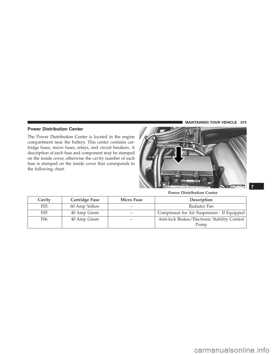
Power Distribution Center
The Power Distribution Center is located in the engine
compartment near the battery. This center contains car-
tridge fuses, micro fuses, relays, and circuit breakers. A
description of each fuse and component may be stamped
on the inside cover, otherwise the cavity number of each
fuse is stamped on the inside cover that corresponds to
the following chart.
Cavity Cartridge Fuse Micro Fuse Description
F03 60 Amp Yellow – Radiator Fan
F05 40 Amp Green – Compressor for Air Suspension - If Equipped
F06 40 Amp Green – Anti-lock Brakes/Electronic Stability Control
Pump
Power Distribution Center
7
MAINTAINING YOUR VEHICLE 575
Page 580 of 636
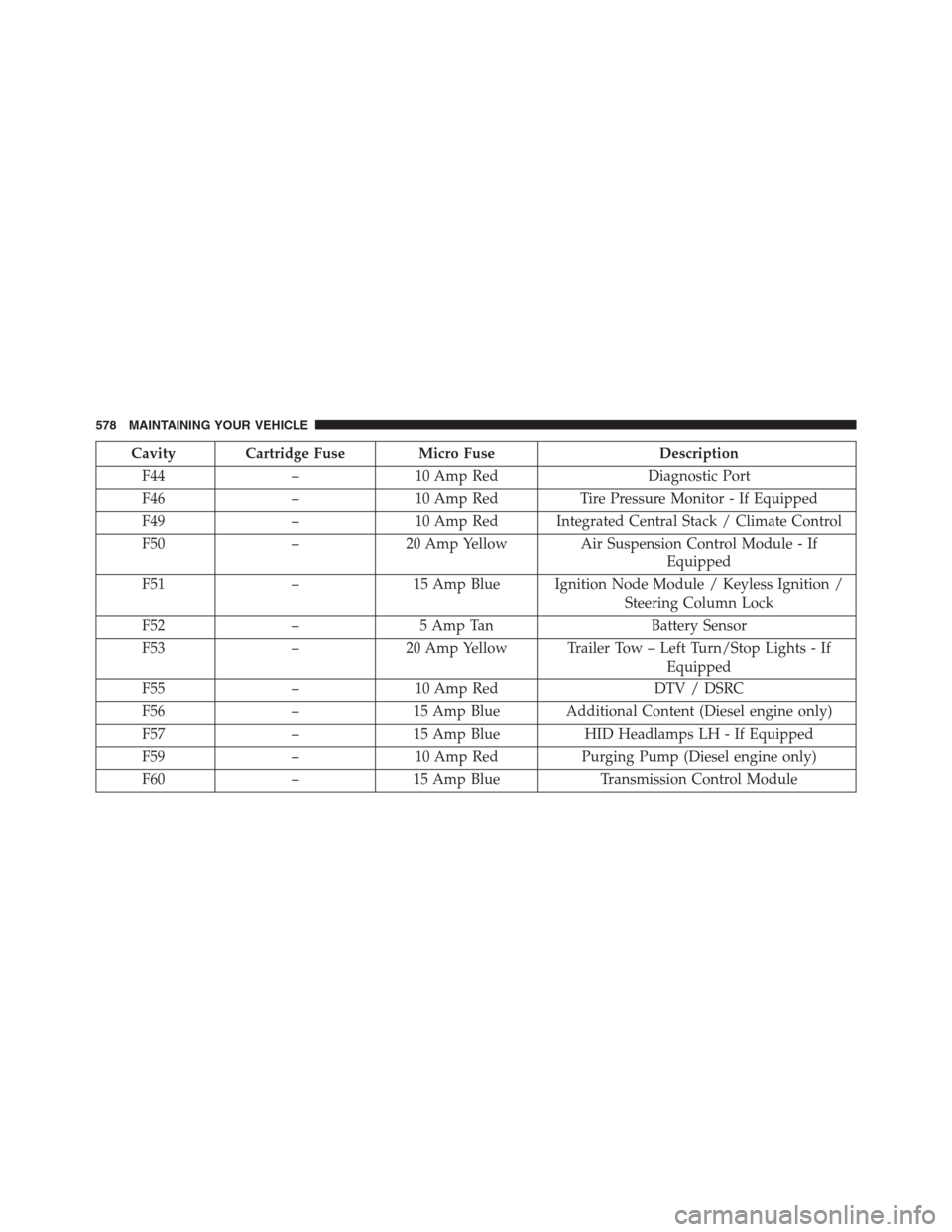
Cavity Cartridge Fuse Micro Fuse Description
F44 – 10 Amp Red Diagnostic Port
F46 – 10 Amp Red Tire Pressure Monitor - If Equipped
F49 – 10 Amp Red Integrated Central Stack / Climate Control
F50 – 20 Amp Yellow Air Suspension Control Module - If
Equipped
F51 – 15 Amp Blue Ignition Node Module / Keyless Ignition /
Steering Column Lock
F52 – 5 Amp Tan Battery Sensor
F53 – 20 Amp Yellow Trailer Tow – Left Turn/Stop Lights - If
Equipped
F55 – 10 Amp Red DTV / DSRC
F56 – 15 Amp Blue Additional Content (Diesel engine only)
F57 – 15 Amp Blue HID Headlamps LH - If Equipped
F59 – 10 Amp Red Purging Pump (Diesel engine only)
F60 – 15 Amp Blue Transmission Control Module
578 MAINTAINING YOUR VEHICLE
Page 583 of 636
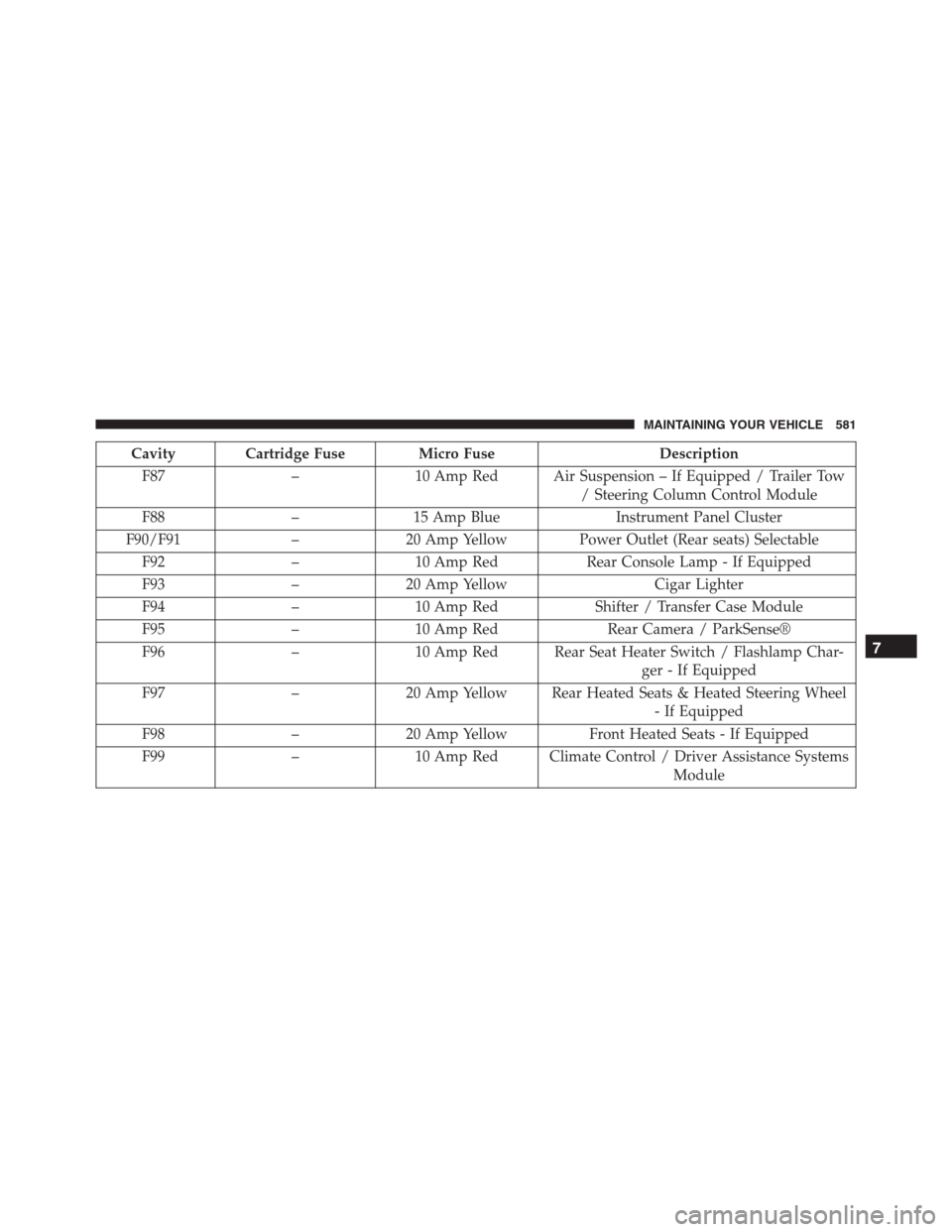
Cavity Cartridge Fuse Micro Fuse Description
F87 – 10 Amp Red Air Suspension – If Equipped / Trailer Tow
/ Steering Column Control Module
F88 – 15 Amp Blue Instrument Panel Cluster
F90/F91 – 20 Amp Yellow Power Outlet (Rear seats) Selectable
F92 – 10 Amp Red Rear Console Lamp - If Equipped
F93 – 20 Amp Yellow Cigar Lighter
F94 – 10 Amp Red Shifter / Transfer Case Module
F95 – 10 Amp Red Rear Camera / ParkSense®
F96 – 10 Amp Red Rear Seat Heater Switch / Flashlamp Char-
ger - If Equipped
F97 – 20 Amp Yellow Rear Heated Seats & Heated Steering Wheel
- If Equipped
F98 – 20 Amp Yellow Front Heated Seats - If Equipped
F99 – 10 Amp Red Climate Control / Driver Assistance Systems
Module
7
MAINTAINING YOUR VEHICLE 581
Page 602 of 636
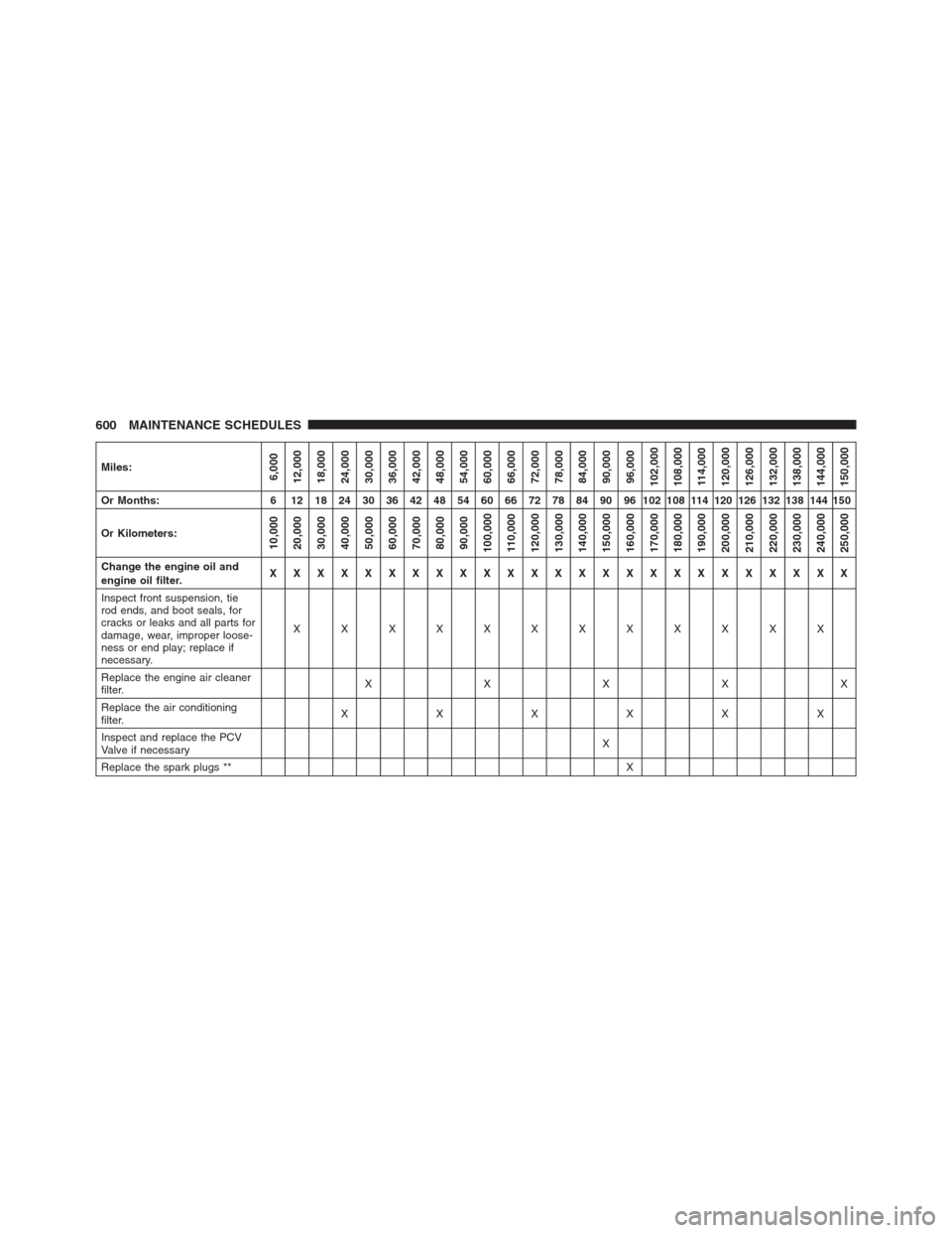
Miles:6,000
12,000
18,000
24,000
30,000
36,000
42,000
48,000
54,000
60,000
66,000
72,000
78,000
84,000
90,000
96,000
102,000
108,000
114,000
120,000
126,000
132,000
138,000
144,000
150,000
Or Months: 6 12 18 24 30 36 42 48 54 60 66 72 78 84 90 96 102 108 114 120 126 132 138 144 150
Or Kilometers:
10,000
20,000
30,000
40,000
50,000
60,000
70,000
80,000
90,000
100,000
110,000
120,000
130,000
140,000
150,000
160,000
170,000
180,000
190,000
200,000
210,000
220,000
230,000
240,000
250,000
Change the engine oil and
engine oil filter.XXXXXXXXXXXXXXXXXXXXXXXXX
Inspect front suspension, tie
rod ends, and boot seals, for
cracks or leaks and all parts for
damage, wear, improper loose-
ness or end play; replace if
necessary.XXXXXXXXXXXX
Replace the engine air cleaner
filter.XXXXX
Replace the air conditioning
filter.XXXXXX
Inspect and replace the PCV
Valve if necessaryX
Replace the spark plugs **X
600 MAINTENANCE SCHEDULES