key JEEP GRAND CHEROKEE 2016 WK2 / 4.G SRT Service Manual
[x] Cancel search | Manufacturer: JEEP, Model Year: 2016, Model line: GRAND CHEROKEE, Model: JEEP GRAND CHEROKEE 2016 WK2 / 4.GPages: 723, PDF Size: 5.54 MB
Page 167 of 723
3. Once the profile has been recalled, push and releasethe SET (S) button on the memory switch.
4. Within five seconds, push and release button (1) or (2) accordingly. “Memory Profile Set” (1 or 2) will display
in the instrument cluster.
5. Push and release the LOCK button on the RKE Key Fob within 10 seconds.
NOTE: Your RKE key fobs can be unlinked to your
memory settings by pushing the SET (S) button, and
within 10 seconds, followed by pushing the UNLOCK
button on the RKE key fob.
Memory Position Recall
NOTE: The vehicle must be in PARK to recall memory
positions. If a recall is attempted when the vehicle is not
in PARK, a message will be displayed in the Driver
Information Display (DID). Driver One Memory Position Recall
•
To recall the memory settings for driver one using the
memory switch, push MEMORY button number 1 on
the memory switch.
• To recall the memory settings for driver one using the
RKE key fob, push the UNLOCK button on the RKE
key fob linked to memory position 1.
Driver Two Memory Position Recall
• To recall the memory setting for driver two using the
memory switch, push MEMORY button number 2 on
the memory switch.
• To recall the memory settings for driver two using the
RKE key fob, push the UNLOCK button on the RKE
key fob linked to memory position 2.
A recall can be cancelled by pushing any of the MEMORY
buttons during a recall (S, 1, or 2). When a recall is
3
UNDERSTANDING THE FEATURES OF YOUR VEHICLE 165
Page 175 of 723
Fog Lights — If Equipped
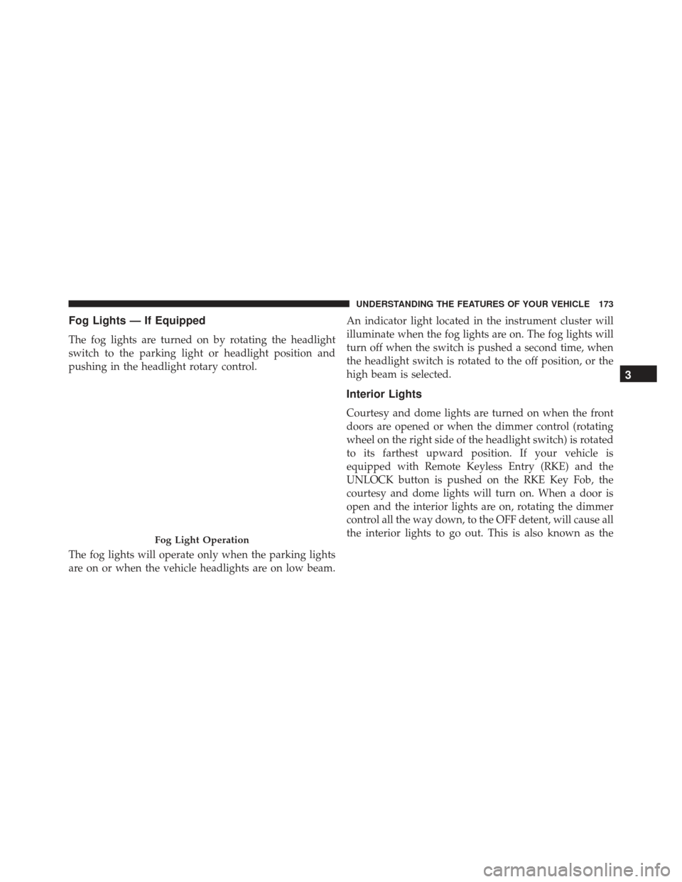
The fog lights are turned on by rotating the headlight
switch to the parking light or headlight position and
pushing in the headlight rotary control.
The fog lights will operate only when the parking lights
are on or when the vehicle headlights are on low beam.An indicator light located in the instrument cluster will
illuminate when the fog lights are on. The fog lights will
turn off when the switch is pushed a second time, when
the headlight switch is rotated to the off position, or the
high beam is selected.
Interior Lights
Courtesy and dome lights are turned on when the front
doors are opened or when the dimmer control (rotating
wheel on the right side of the headlight switch) is rotated
to its farthest upward position. If your vehicle is
equipped with Remote Keyless Entry (RKE) and the
UNLOCK button is pushed on the RKE Key Fob, the
courtesy and dome lights will turn on. When a door is
open and the interior lights are on, rotating the dimmer
control all the way down, to the OFF detent, will cause all
the interior lights to go out. This is also known as the
Fog Light Operation
3
UNDERSTANDING THE FEATURES OF YOUR VEHICLE 173
Page 177 of 723
Battery Saver
To protect the life of your vehicle’s battery, load shedding
is provided for both the interior and exterior lights.
If the ignition is OFF and any door is left ajar for 10
minutes or the dimmer control is rotated all the way up
to the dome ON position for 10 minutes, the interior
lights will automatically turn off.
NOTE:Battery saver mode is cancelled if the ignition is
ON.
If the headlights remain on while the ignition is cycled
OFF, the exterior lights will automatically turn off after
eight minutes. If the headlights are turned on and left on
for eight minutes while the ignition is OFF, the exterior
lights will automatically turn off.
Front Map/Reading Lights — If Equipped
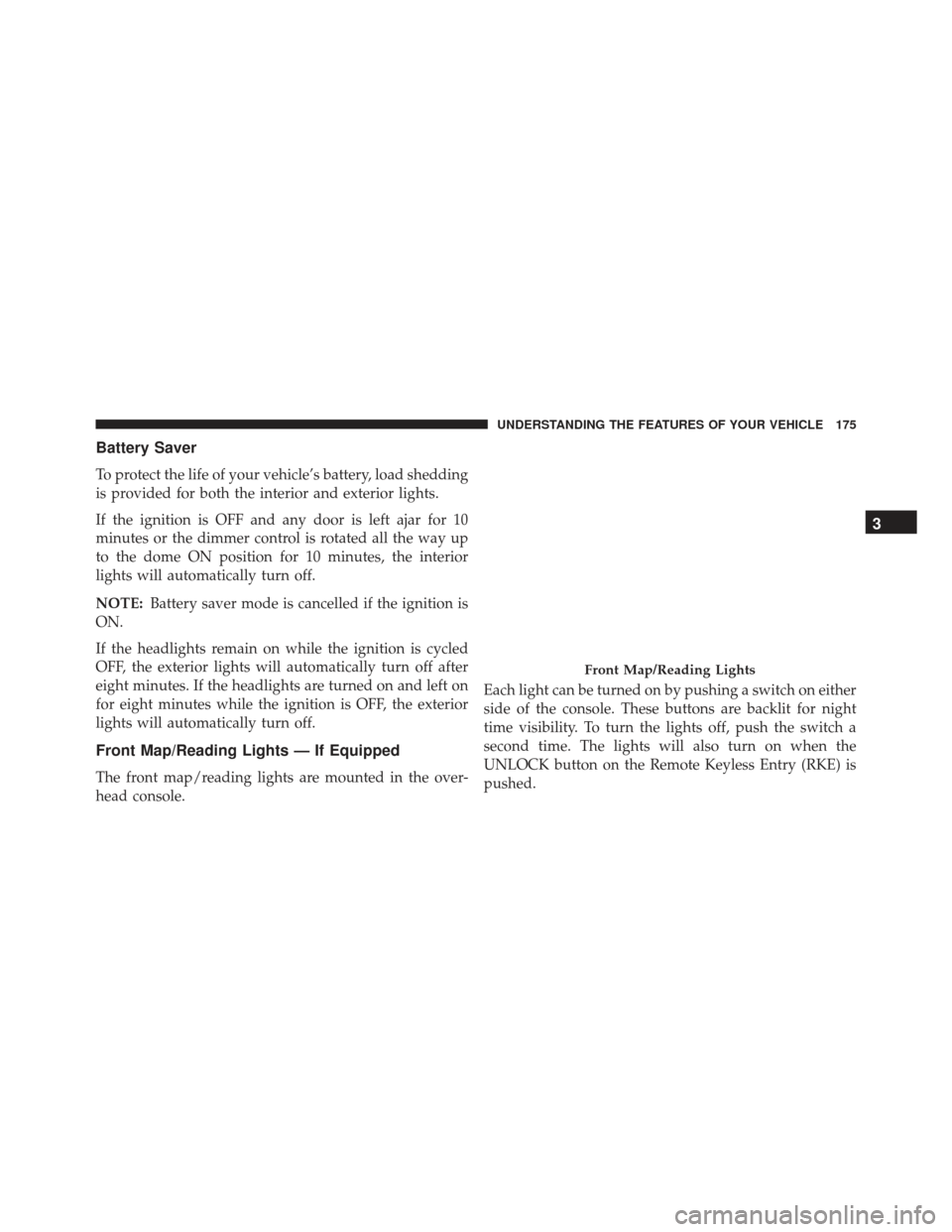
The front map/reading lights are mounted in the over-
head console. Each light can be turned on by pushing a switch on either
side of the console. These buttons are backlit for night
time visibility. To turn the lights off, push the switch a
second time. The lights will also turn on when the
UNLOCK button on the Remote Keyless Entry (RKE) is
pushed.
Front Map/Reading Lights
3
UNDERSTANDING THE FEATURES OF YOUR VEHICLE 175
Page 187 of 723
NOTE:For vehicles equipped with Driver Memory Seat,
you can use your Remote Keyless Entry (RKE) Key Fob
or the memory switch on the driver’s door trim panel to
return the tilt/telescopic steering column to pre-
programmed positions. Refer to “Driver Memory Seat”
in this section for further information.
WARNING!
Do not adjust the steering column while driving.
Adjusting the steering column while driving or driv-
ing with the steering column unlocked, could cause
the driver to lose control of the vehicle. Failure to
follow this warning may result in serious injury or
death.
HEATED STEERING WHEEL — IF EQUIPPED
The steering wheel contains a heating element that helps
warm your hands in cold weather. The heated steering
wheel has only one temperature setting. Once the heated
steering wheel has been turned on it will operate for up
to 80 minutes before automatically shutting off. The
heated steering wheel can shut off early or may not turn
on when the steering wheel is already warm.
The heated steering wheel control button is located
within the Uconnect system. You can gain access to the
control button through the climate screen or the controls
screen.
• Press the heated steering wheel button
once to
turn the heating element ON.
• Press the heated steering wheel buttona second
time to turn the heating element OFF. 3
UNDERSTANDING THE FEATURES OF YOUR VEHICLE 185
Page 261 of 723
COMMANDVIEW SUNROOF WITH POWER
SHADE — IF EQUIPPED
The CommandView sunroof switch is located to the left
between the sun visors on the overhead console.
The power shade switch is located to the right between
the sun visors on the overhead console.
WARNING!
•Never leave children unattended in a vehicle, or
with access to an unlocked vehicle. Never leave the
Key Fob in or near the vehicle, or in a location
(Continued)
CommandView Sunroof And Power Shade Switches
3
UNDERSTANDING THE FEATURES OF YOUR VEHICLE 259
Page 262 of 723
WARNING!(Continued)
accessible to children. Do not leave the ignition of
a vehicle equipped with Keyless Enter-N-Go in the
ACC or ON/RUN mode. Occupants, particularly
unattended children, can become entrapped by the
power sunroof while operating the power sunroof
switch. Such entrapment may result in serious
injury or death.
• In a collision, there is a greater risk of being thrown
from a vehicle with an open sunroof. You could
also be seriously injured or killed. Always fasten
your seat belt properly and make sure all passen-
gers are also properly secured.
• Do not allow small children to operate the sunroof.
Never allow your fingers, other body parts, or any
object, to project through the sunroof opening.
Injury may result.
Opening Sunroof — Express
Push the switch rearward and release it within one-half
second. The sunroof and sunshade will open automati-
cally from any position. The sunroof and sunshade will
open fully and stop automatically. This is called “Express
Open.” During Express Open operation, any other actua-
tion of the sunroof switch will stop the sunroof.
Opening Sunroof — Manual Mode
To open the sunroof, push and hold the switch rearward
to full open. Any release of the switch will stop the
movement. The sunroof and sunshade will remain in a
partially opened condition until the sunroof switch is
pushed again.
Closing Sunroof — Express
Push the switch forward and release it within one-half
second and the sunroof will close automatically from any
260 UNDERSTANDING THE FEATURES OF YOUR VEHICLE
Page 265 of 723
windows down, or the sunroof (if equipped) in certain
open or partially open positions. This is a normal occur-
rence and can be minimized. If the buffeting occurs with
the rear windows open, open the front and rear windows
together to minimize the buffeting. If the buffeting occurs
with the sunroof open, adjust the sunroof opening to
minimize the buffeting or open any window.
Sunroof Maintenance
Use only a non-abrasive cleaner and a soft cloth to clean
the glass panel.
Ignition Off Operation
NOTE:
•The power sunroof switch can remain active in Acces-
sory Delay for up to approximately ten minutes after
the vehicles ignition is placed to the Off position.
Opening either front door will cancel this feature. •
This feature is programmable using the Uconnect
System. Refer to “Uconnect Settings” in “Understand-
ing Your Instrument Panel” for further information.
ELECTRICAL POWER OUTLETS
Your vehicle is equipped with 12 Volt (13 Amp) power
outlets that can be used to power cellular phones, small
electronics and other low powered electrical accessories.
The power outlets are labeled with either a “key” or a
“battery” symbol to indicate how the outlet is powered.
Power outlets labeled with a “key” are powered when
the ignition is in the ON or ACC position, while the
outlets labeled with a “battery” are connected directly to
the battery and powered at all times.
3
UNDERSTANDING THE FEATURES OF YOUR VEHICLE 263
Page 291 of 723
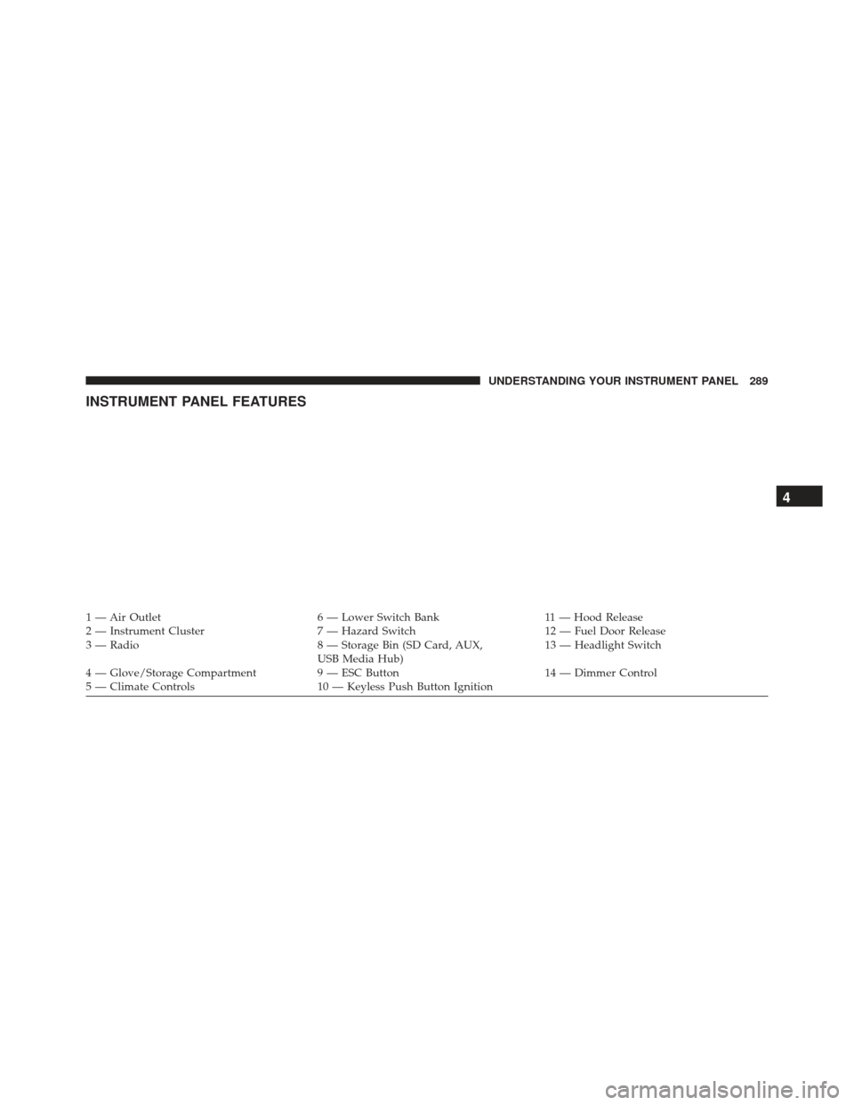
INSTRUMENT PANEL FEATURES
1 — Air Outlet6 — Lower Switch Bank11 — Hood Release
2 — Instrument Cluster 7 — Hazard Switch12 — Fuel Door Release
3 — Radio 8 — Storage Bin (SD Card, AUX,
USB Media Hub) 13 — Headlight Switch
4 — Glove/Storage Compartment 9 — ESC Button14 — Dimmer Control
5 — Climate Controls 10 — Keyless Push Button Ignition
4
UNDERSTANDING YOUR INSTRUMENT PANEL 289
Page 302 of 723
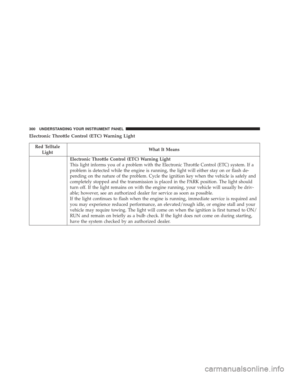
Electronic Throttle Control (ETC) Warning Light
Red TelltaleLight What It Means
Electronic Throttle Control (ETC) Warning Light
This light informs you of a problem with the Electronic Throttle Control (ETC) system. If a
problem is detected while the engine is running, the light will either stay on or flash de-
pending on the nature of the problem. Cycle the ignition key when the vehicle is safely and
completely stopped and the transmission is placed in the PARK position. The light should
turn off. If the light remains on with the engine running, your vehicle will usually be driv-
able; however, see an authorized dealer for service as soon as possible.
If the light continues to flash when the engine is running, immediate service is required and
you may experience reduced performance, an elevated/rough idle, or engine stall and your
vehicle may require towing. The light will come on when the ignition is first turned to ON/
RUN and remain on briefly as a bulb check. If the light does not come on during starting,
have the system checked by an authorized dealer.
300 UNDERSTANDING YOUR INSTRUMENT PANEL
Page 307 of 723
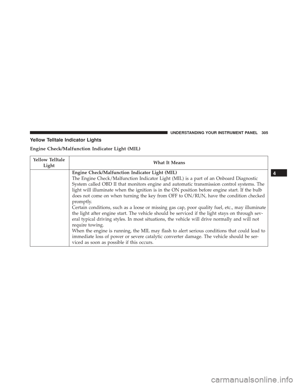
Yellow Telltale Indicator Lights
Engine Check/Malfunction Indicator Light (MIL)
Yellow TelltaleLight What It Means
Engine Check/Malfunction Indicator Light (MIL)
The Engine Check/Malfunction Indicator Light (MIL) is a part of an Onboard Diagnostic
System called OBD II that monitors engine and automatic transmission control systems. The
light will illuminate when the ignition is in the ON position before engine start. If the bulb
does not come on when turning the key from OFF to ON/RUN, have the condition checked
promptly.
Certain conditions, such as a loose or missing gas cap, poor quality fuel, etc., may illuminate
the light after engine start. The vehicle should be serviced if the light stays on through sev-
eral typical driving styles. In most situations, the vehicle will drive normally and will not
require towing.
When the engine is running, the MIL may flash to alert serious conditions that could lead to
immediate loss of power or severe catalytic converter damage. The vehicle should be ser-
viced as soon as possible if this occurs.4
UNDERSTANDING YOUR INSTRUMENT PANEL 305