change time JEEP GRAND CHEROKEE 2016 WK2 / 4.G Owner's Manual
[x] Cancel search | Manufacturer: JEEP, Model Year: 2016, Model line: GRAND CHEROKEE, Model: JEEP GRAND CHEROKEE 2016 WK2 / 4.GPages: 276, PDF Size: 10.84 MB
Page 110 of 276
USB Port
• Connect your compatible device using a USB cable into the USB Port. USBMemory sticks with audio files can also be used. Audio from the device can be
played on the vehicles sound system while providing metadata (artist, track title,
album, etc.) information on the radio display.
• When connected, the compatible USB device can be controlled using the radio or Steering Wheel Audio Controls to play, skip to the next or previous track, browse,
and list the contents.
• The battery charges when plugged into the USB port (if supported by the specific device).
• To route the USB cable out of the center console, use the access cut out.
NOTE:
When connecting your device for the first time, the system may take several minutes
to read your music, depending on the number of files. For example, the system will
take approximately five minutes for every 1,000 songs loaded on the device. Also
during the reading process, the Shuffle and Browse functions will be disabled. This
process is needed to ensure the full use of your features and only happens the first
time it is connected. After the first time, the reading process of your device will take
considerably less time unless changes are made or new songs are added to the
playlist.
SD Card
• Play songs stored on an SD card inserted into the SD card slot.
• Song playback can be controlled using the radio or Steering Wheel Audio Controls to play, skip to the next or previous track, browse, and list the contents.
Bluetooth Streaming Audio
• If using a Bluetooth equipped device you may also be able to stream music to your vehicle's sound system. Your connected device must be Bluetooth compatible and
paired with your system (see Uconnect Phone for pairing instructions). You can
access the music from your connected Bluetooth device by pressing the Bluetooth
button on the touchscreen while in Media mode.
ELECTRONICS
108
Page 151 of 276
DID Screen Setup
The following settings allow you to change what information is displayed in the
instrument cluster as well as the location that information is displayed:
• None• Average MPH (L/100km)
• Compass • Current MPH (L/100km)
• Outside Temperature • Trip A (Distance Only)
• Time • Trip B (Distance Only)
• Range to Empty
Trip A
Push and release the UPorDOWNarrow button until the Trip A icon is
highlighted in the DID (Toggle left or right to select Trip A or Trip B). Push and release
the OKbutton to display the Trip A information.
Trip B
Push and release the UPorDOWNarrow button until the Trip B icon is
highlighted in the DID (Toggle left or right to select Trip A or Trip B). Push and release
the OKbutton to display the Trip B information.
Fuel Economy
Push and release the UPorDOWNarrow button until the Fuel Economy icon
is highlighted. Push the RIGHT
arrow button and the next screen will display the
following:
• Average Fuel Economy/Miles Per Gallon (MPG Bar graph)
• Range To Empty (RTE)
• Current Miles Per Gallon (MPG)
ELECTRONICS
149
Page 153 of 276
2. Place the hand-held transmitter 1 to 3 inches (3 to 8 cm) away from theHomeLink button you wish to program while keeping the HomeLink indicator light
in view.
3. Push and hold the HomeLink button you want to program while you push and hold the hand-held transmitter button.
4. Continue to hold both buttons and observe the indicator light. The HomeLink indicator will flash slowly and then rapidly after HomeLink has received the
frequency signal from the hand-held transmitter. Release both buttons after the
indicator light changes from slow to rapid.
5. At the garage door opener motor (in the garage), locate the “LEARN” or “TRAINING” button. This can usually be found where the hanging antenna wire
is attached to the garage door opener motor. Firmly push and release the
“LEARN” or “TRAINING” button.
NOTE:
You have 30 seconds in which to initiate the next step after the LEARN button has
been pushed.
6. Return to the vehicle and push the programmed HomeLink button twice (holding the button for two seconds each time). If the device is plugged in and activates,
programming is complete.
NOTE:
If the device does not activate, push the button a third time (for two seconds) to
complete the training.
7. To program the remaining two HomeLink buttons, repeat each step for each remaining button. DO NOT erase the channels.
Programming A Non-Rolling Code
NOTE:
For programming Garage Door Openers manufactured before 1995.
1. Place the ignition switch to the ON/RUN position.
2. Place the hand-held transmitter 1 to 3 inches (3 to 8 cm) away from theHomeLink button you wish to program while keeping the HomeLink indicator light
in view.
3. Push and hold the HomeLink button you want to program while you push and hold the hand-held transmitter button.
4. Continue to hold both buttons and observe the indicator light. The HomeLink indicator will flash slowly and then rapidly after HomeLink has received the
frequency signal from the hand-held transmitter. Release both buttons after the
indicator light changes from slow to rapid.
ELECTRONICS
151
Page 159 of 276
5. Using a ballpoint pen or similar object, press and hold the recessed transfer caseNEUTRAL (N) button (located by the selector switch) for four seconds. The light
behind the N symbol will blink, indicating shift in progress. The light will stop
blinking (stay on solid) when the shift to NEUTRAL (N) is complete. A “FOUR
WHEEL DRIVE SYSTEM IN NEUTRAL” message will display on the Driver
Information Display (DID).
6. After the shift is completed and the NEUTRAL (N) light stays on, release the NEUTRAL (N) button.
7. Shift the transmission into REVERSE.
8. Release the brake pedal for five seconds and ensure that there is no vehicle movement.
9. Press and hold the brake pedal. Shift the transmission back into NEUTRAL
10. Firmly apply the parking brake.
11. With the transmission and transfer case in NEUTRAL, press and hold the ENGINE START/STOP button until the engine turns off.
12. Move the transmission gear selector to PARK. Release the brake pedal.
13. Push the ENGINE STOP/START button twice (without pressing the brake pedal), to turn the ignition switch to the OFF position
Repeat these Steps 1 through 5 to shift out of NEUTRAL.
SELEC-TERRAIN
Selec-Terrain combines the capabilities of the vehicle control systems, along with
driver input, to provide the best performance for all terrains.
Rotate the mode control knob to select the following Selec-Terrain positions:
Snow – Tuning set for additional stability in inclement weather. Use on and off road
on loose traction surfaces such as snow. When in Snow mode (depending on certain
operating conditions), the transmission may use second gear (rather than first gear)
during launches, to minimize wheel slippage. If equipped with air suspension, the
level will change to Normal Ride Height (NRH).
Auto – Fully automatic full time four-wheel drive operation can be used on and off
road. Balances traction with seamless steering feel to provide improved handling and
acceleration over two-wheel drive vehicles. If equipped with air suspension, the level
will change to NRH.
Sand – Off road calibration for use on low traction surfaces such as sand or wet grass.
Driveline is maximized for traction. Some binding may be felt on less forgiving
surfaces. The electronic brake controls are set to limit traction control management
of throttle and wheel spin. If equipped with air suspension, the level will change to
NRH.
OFF-ROAD CAPABILITIES (4WD OPERATION)
157
Page 160 of 276
Mud– Off road calibration for use on low traction surfaces such as mud. Driveline is
maximized for traction. Some binding may be felt on less forgiving surfaces. The
electronic brake controls are set to limit traction control management of throttle and
wheel spin. If equipped with air suspension, the level will change to Off-Road 1.
Rock – Off-road calibration only available in 4WD Low range. The vehicle is raised (if
equipped with Air Suspension) for improved ground clearance. Traction based tuning
with improved steer-ability for use on high traction off-road surfaces. Activate the Hill
Descent Control for steep downhill control. Use for low speed obstacles such as large
rocks, deep ruts, etc. If equipped with air suspension, the vehicle level will change
to Off-Road 2. If the Selec-Terrain switch is in ROCK mode, and the transfer case is
switched from 4WD Low to 4WD High, the Selec-Terrain system will return to AUTO.
QUADRA-LIFT
The Quadra-Lift air suspension system provides full time load leveling capability
along with the benefit of being able to adjust vehicle height by the push of a button.
Quadra-Lift is available with both Quadra-Trac II and Quadra-Drive II.
• The system requires that the engine be running for all changes. When lowering
the vehicle all of the doors, including
the liftgate, must be closed.
• The Quadra-Lift air suspension system uses a lifting and lowering pattern
which keeps the headlights from shin-
ing into oncoming traffic. When raising
the vehicle, the rear of the vehicle will
move up first and then the front. When
lowering the vehicle, the front will
move down first and then the rear.
• After the engine is turned off, you may notice that the air suspension system
operates briefly. This is normal. The
system is correcting the position of the
vehicle.
• To assist with changing a spare tire, the Quadra-Lift air suspension system
has a feature which allows the automatic leveling to be disabled. The feature
controls are located in the radio screen. Driving the vehicle over 5 mph (8 km/h)
will return the air suspension to normal operation.
• An audible chime will be heard whenever a system error has been detected.
Quadra-Lift Control
1 — UP Button
2 — DOWN Button
OFF-ROAD CAPABILITIES (4WD OPERATION)
158
Page 182 of 276
DIESEL ENGINE BREAK-IN RECOMMENDATIONS
The diesel engine does not require a break-in period due to its construction. Normal
operation is allowed, providing the following recommendations are followed:
• Warm up the engine before placing it under load.
• Do not operate the engine at idle for prolonged periods.
• Use the appropriate transmission gear to prevent engine lugging.
• Observe vehicle oil pressure and temperature indicators.
• Check the coolant and oil levels frequently.
• Vary throttle position at highway speeds when carrying or towing significantweight.
NOTE:
Light duty operation such as light trailer towing or no load operation will extend the
time before the engine is at full efficiency. Reduced fuel economy and power may be
seen at this time.
The engine oil installed in the engine at the factory is a high-quality energy
conserving type lubricant. Oil changes should be consistent with anticipated climate
conditions under which vehicle operations will occur. NON-DETERGENT OR
STRAIGHT MINERAL OILS MUST NEVER BE USED.
DIESEL ENGINE STARTING PROCEDURES
Normal Starting Procedure
1. Apply the parking brake.
2. Ensure the gear selector is in the PARK position.
3. Press and hold the brake pedal while pushing the ENGINE START/STOP button once and the system will engage the starter to crank the engine.
NOTE: • A delay of the start of up to five seconds is possible under very cold conditions.The “Wait to Start” telltale will be illuminated during the pre-heat process,
When the engine Wait To Start light goes off the engine will automatically crank.
• If you wish to stop the cranking of the engine prior to the engine starting, push the button again.
4. Check that the oil pressure warning light has turned off.
5. Release the parking brake.
DIESEL
180
Page 186 of 276
Exhaust Service Required — See Dealer Now
This message indicates regeneration has been disabled due to a system malfunction.
The Powertrain control Module (PCM) will register a fault code and the instrument
panel will display the Malfunction Indicator Light (MIL).
CAUTION!
See your authorized dealer, as damage to the exhaust system could occur soon
with continued operation.
Exhaust Filter Full — Power Reduced See Dealer
The PCM derates the engine in order to limit the likelihood of permanent damage to
the after-treatment system. If this condition is not corrected and a dealer service is
not performed, extensive exhaust after-treatment damage can occur. Have your
vehicle serviced by your local authorized dealer.
NOTE:
Failing to follow the oil change indicator, changing your oil and resetting the oil
change indicator by 0 miles remaining will prevent the diesel exhaust filter from
performing it's cleaning routine. This will shortly result in a Malfunction Indicator
Light (MIL) and reduced engine power. Only an authorized dealer will be able to
correct this condition.
CAUTION!
See your authorized dealer, as damage to the exhaust system could occur with the
exhaust filter full.
DIESEL EXHAUST FLUID
Diesel Exhaust Fluid (DEF) sometimes known simply by the name of its active
component, UREA – is a key component of selective catalytic reduction (SCR)
systems, which help diesel vehicles meet stringent emission regulations. DEF is a
liquid reducing agent that reacts with engine exhaust in the presence of a catalyst to
convert smog-forming nitrogen oxides (NOx) into harmless nitrogen and water vapor.
Your vehicle is equipped with a Selective Catalytic Reduction system in order to meet
the very stringent diesel emissions standards required by the Environmental Protec-
tion Agency. Selective Catalytic Reduction (SCR) is the first and only technology in
decades to be as good for the environment as it is good for business and vehicle
performance.
DIESEL
184
Page 194 of 276
Your vehicle has also been equipped with a TPMS malfunction indicator to indicate
when the system is not operating properly. The TPMS malfunction indicator is
combined with the low tire pressure telltale. When the system detects a malfunction,
the telltale will flash for approximately one minute and then remain continuously
illuminated. This sequence will continue each time the vehicle is restarted as long as
the malfunction exists.
When the malfunction indicator is illuminated, the system may not be able to detect
or signal low tire pressure as intended. TPMS malfunctions may occur for a variety of
reasons, including the installation of replacement or alternate tires or wheels on the
vehicle that prevent the TPMS from functioning properly. Always check the TPMS
malfunction telltale after replacing one or more tires or wheels on your vehicle, to
ensure that the replacement or alternate tires and wheels allow the TPMS to continue
to function properly.
NOTE:
Tire pressures change by approximately 1 psi (7 kPa) per 12° F (7° C) of air
temperature change. Keep this in mind when checking tire pressure inside a garage,
especially in the Winter. Example: If garage temperature is 68°F (20°C) and the
outside temperature is 32°F (0°C), then the cold tire inflation pressure should be
increased by 3 psi (21 kPa), which equals 1 psi (7 kPa) for every 12°F (7°C) for this
outside temperature condition.
CAUTION!
The TPMS has been optimized for the original equipment tires and wheels. TPMS
pressures and warning have been established for the tire size equipped on your
vehicle. Undesirable system operation or sensor damage may result when using
replacement equipment that is not of the same size, type, and/or style. Aftermar-
ket wheels can cause sensor damage. Do not use tire sealant from a can, or
balance beads if your vehicle is equipped with a TPMS, as damage to the sensors
may result.
– Seat Belt Reminder Light
When the ignition switch is first turned to the ON/RUN position, this light will turn on
for four to eight seconds as a bulb check. During the bulb check, if the driver's seat
belt is unbuckled, a chime will sound. After the bulb check or when driving, if the
driver or front passenger seat belt remains unbuckled, the Seat Belt Indicator Light
will flash or remain on continuously. Refer to “Seat Belt Systems” in “Things To
Know Before Starting” in your Owner’s Manual on the DVD for further information.
WHAT TO DO IN EMERGENCIES
192
Page 198 of 276
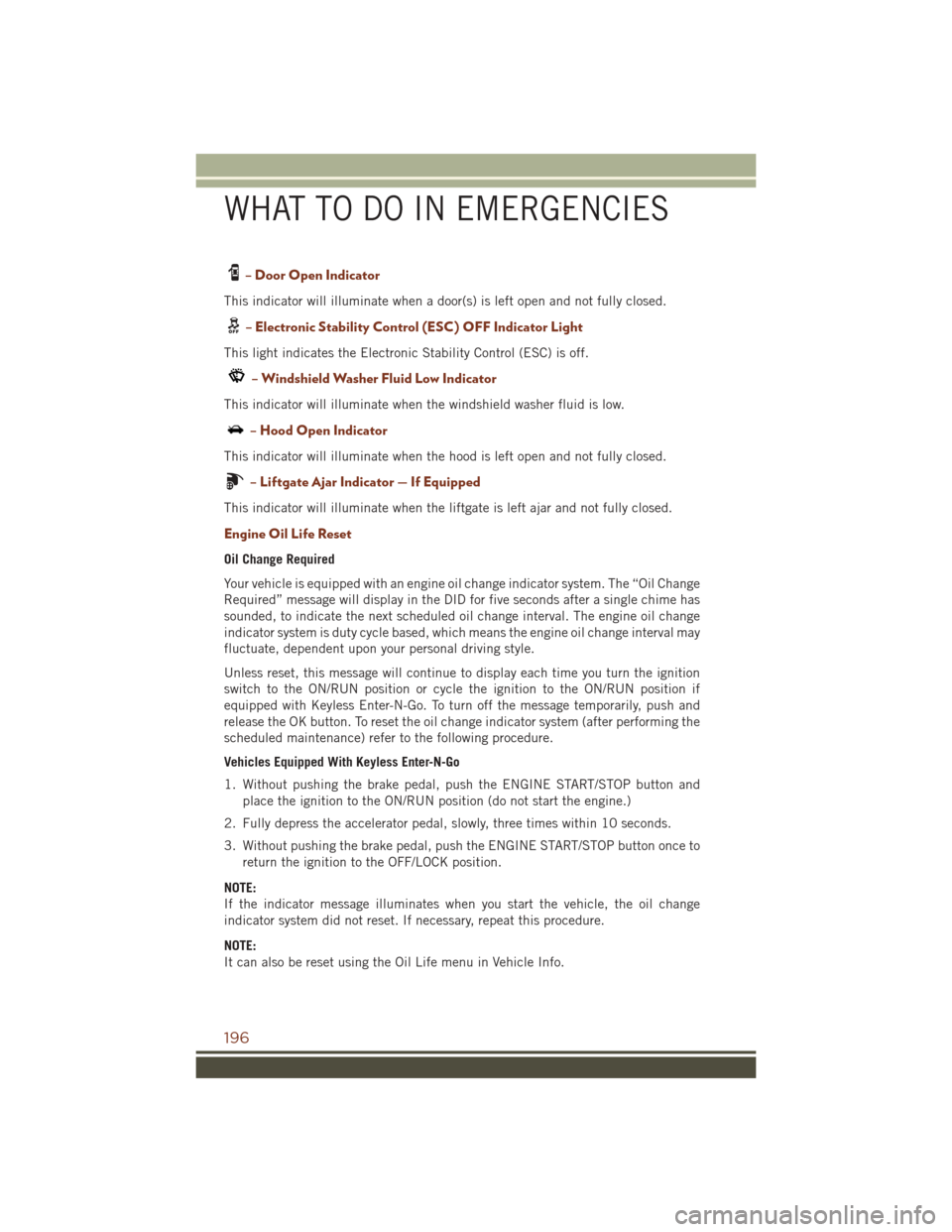
– Door Open Indicator
This indicator will illuminate when a door(s) is left open and not fully closed.
– Electronic Stability Control (ESC) OFF Indicator Light
This light indicates the Electronic Stability Control (ESC) is off.
– Windshield Washer Fluid Low Indicator
This indicator will illuminate when the windshield washer fluid is low.
– Hood Open Indicator
This indicator will illuminate when the hood is left open and not fully closed.
– Liftgate Ajar Indicator — If Equipped
This indicator will illuminate when the liftgate is left ajar and not fully closed.
Engine Oil Life Reset
Oil Change Required
Your vehicle is equipped with an engine oil change indicator system. The “Oil Change
Required” message will display in the DID for five seconds after a single chime has
sounded, to indicate the next scheduled oil change interval. The engine oil change
indicator system is duty cycle based, which means the engine oil change interval may
fluctuate, dependent upon your personal driving style.
Unless reset, this message will continue to display each time you turn the ignition
switch to the ON/RUN position or cycle the ignition to the ON/RUN position if
equipped with Keyless Enter-N-Go. To turn off the message temporarily, push and
release the OK button. To reset the oil change indicator system (after performing the
scheduled maintenance) refer to the following procedure.
Vehicles Equipped With Keyless Enter-N-Go
1. Without pushing the brake pedal, push the ENGINE START/STOP button andplace the ignition to the ON/RUN position (do not start the engine.)
2. Fully depress the accelerator pedal, slowly, three times within 10 seconds.
3. Without pushing the brake pedal, push the ENGINE START/STOP button once to return the ignition to the OFF/LOCK position.
NOTE:
If the indicator message illuminates when you start the vehicle, the oil change
indicator system did not reset. If necessary, repeat this procedure.
NOTE:
It can also be reset using the Oil Life menu in Vehicle Info.
WHAT TO DO IN EMERGENCIES
196
Page 234 of 276
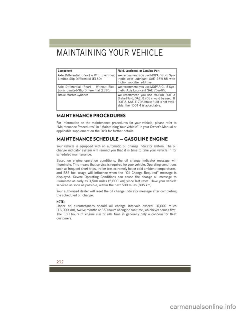
ComponentFluid, Lubricant, or Genuine Part
Axle Differential (Rear) – With Electronic
Limited-Slip Differential (ELSD) We recommend you use MOPAR GL-5 Syn-
thetic Axle Lubricant SAE 75W-85 with
friction modifier additive.
Axle Differential (Rear) – Without Elec-
tronic Limited-Slip Differential (ELSD) We recommend you use MOPAR GL-5 Syn-
thetic Axle Lubricant SAE 75W-85.
Brake Master Cylinder We recommend you use MOPAR DOT 3
Brake Fluid, SAE J1703 should be used. If
DOT 3, SAE J1703 brake fluid is not avail-
able, then DOT 4 is acceptable.
MAINTENANCE PROCEDURES
For information on the maintenance procedures for your vehicle, please refer to
“Maintenance Procedures” in “Maintaining Your Vehicle” in your Owner’s Manual or
applicable supplement on the DVD for further details.
MAINTENANCE SCHEDULE — GASOLINE ENGINE
Your vehicle is equipped with an automatic oil change indicator system. The oil
change indicator system will remind you that it is time to take your vehicle in for
scheduled maintenance.
Based on engine operation conditions, the oil change indicator message will
illuminate. This means that service is required for your vehicle. Operating conditions
such as frequent short-trips, trailer tow, extremely hot or cold ambient temperatures,
and E85 fuel usage will influence when the “Oil Change Required” message is
displayed. Severe Operating Conditions can cause the change oil message to
illuminate as early as 3,500 miles (5,600 km) since last reset. Have your vehicle
serviced as soon as possible, within the next 500 miles (805 km).
Your authorized dealer will reset the oil change indicator message after completing
the scheduled oil change.
NOTE:
Under no circumstances should oil change intervals exceed 10,000 miles
(16,000 km), twelve months or 350 hours of engine run time, whichever comes first.
The 350 hours of engine run or idle time is generally only a concern for fleet
customers.
MAINTAINING YOUR VEHICLE
232