steering wheel JEEP GRAND CHEROKEE 2017 WK2 / 4.G SRT Owners Manual
[x] Cancel search | Manufacturer: JEEP, Model Year: 2017, Model line: GRAND CHEROKEE, Model: JEEP GRAND CHEROKEE 2017 WK2 / 4.GPages: 44, PDF Size: 6.77 MB
Page 11 of 44
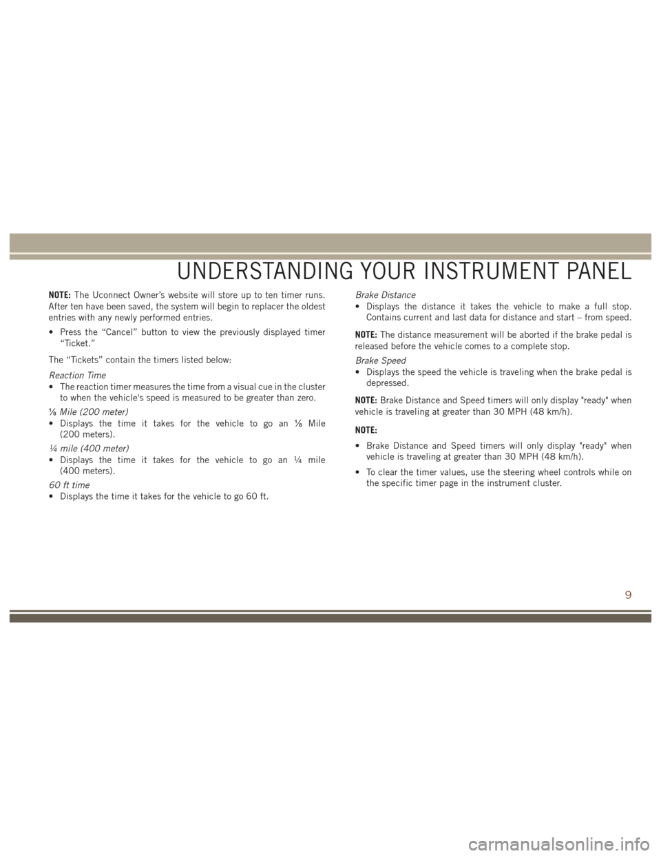
NOTE:The Uconnect Owner’s website will store up to ten timer runs.
After ten have been saved, the system will begin to replacer the oldest
entries with any newly performed entries.
• Press the “Cancel” button to view the previously displayed timer “Ticket.”
The “Tickets” contain the timers listed below:
Reaction Time
• The reaction timer measures the time from a visual cue in the cluster to when the vehicle's speed is measured to be greater than zero.
⅛ Mile (200 meter)
• Displays the time it takes for the vehicle to go an ⅛Mile
(200 meters).
¼ mile (400 meter)
• Displays the time it takes for the vehicle to go an ¼ mile (400 meters).
60 ft time
• Displays the time it takes for the vehicle to go 60 ft. Brake Distance
• Displays the distance it takes the vehicle to make a full stop.
Contains current and last data for distance and start – from speed.
NOTE: The distance measurement will be aborted if the brake pedal is
released before the vehicle comes to a complete stop.
Brake Speed
• Displays the speed the vehicle is traveling when the brake pedal is depressed.
NOTE: Brake Distance and Speed timers will only display "ready" when
vehicle is traveling at greater than 30 MPH (48 km/h).
NOTE:
• Brake Distance and Speed timers will only display "ready" when vehicle is traveling at greater than 30 MPH (48 km/h).
• To clear the timer values, use the steering wheel controls while on the specific timer page in the instrument cluster.
UNDERSTANDING YOUR INSTRUMENT PANEL
9
Page 14 of 44
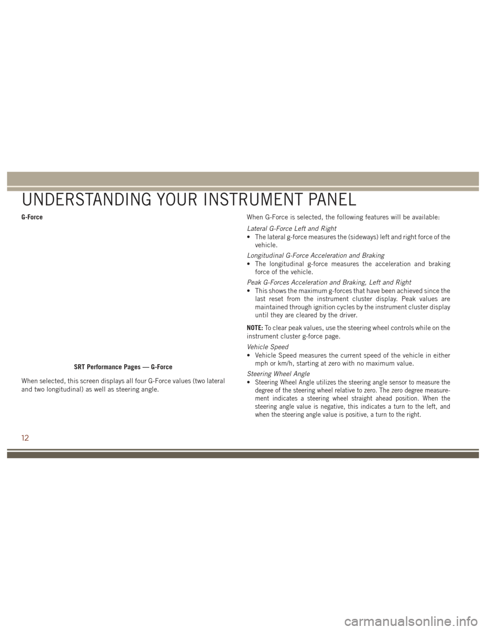
G-Force
When selected, this screen displays all four G-Force values (two lateral
and two longitudinal) as well as steering angle.When G-Force is selected, the following features will be available:
Lateral G-Force Left and Right
• The lateral g-force measures the (sideways) left and right force of the
vehicle.
Longitudinal G-Force Acceleration and Braking
• The longitudinal g-force measures the acceleration and braking force of the vehicle.
Peak G-Forces Acceleration and Braking, Left and Right
• This shows the maximum g-forces that have been achieved since the last reset from the instrument cluster display. Peak values are
maintained through ignition cycles by the instrument cluster display
until they are cleared by the driver.
NOTE: To clear peak values, use the steering wheel controls while on the
instrument cluster g-force page.
Vehicle Speed
• Vehicle Speed measures the current speed of the vehicle in either mph or km/h, starting at zero with no maximum value.
Steering Wheel Angle
•
Steering Wheel Angle utilizes the steering angle sensor to measure the
degree of the steering wheel relative to zero. The zero degree measure-
ment indicates a steering wheel straight ahead position. When the
steering angle value is negative, this indicates a turn to the left, and
when the steering angle value is positive, a turn to the right.
SRT Performance Pages — G-Force
UNDERSTANDING YOUR INSTRUMENT PANEL
12
Page 17 of 44
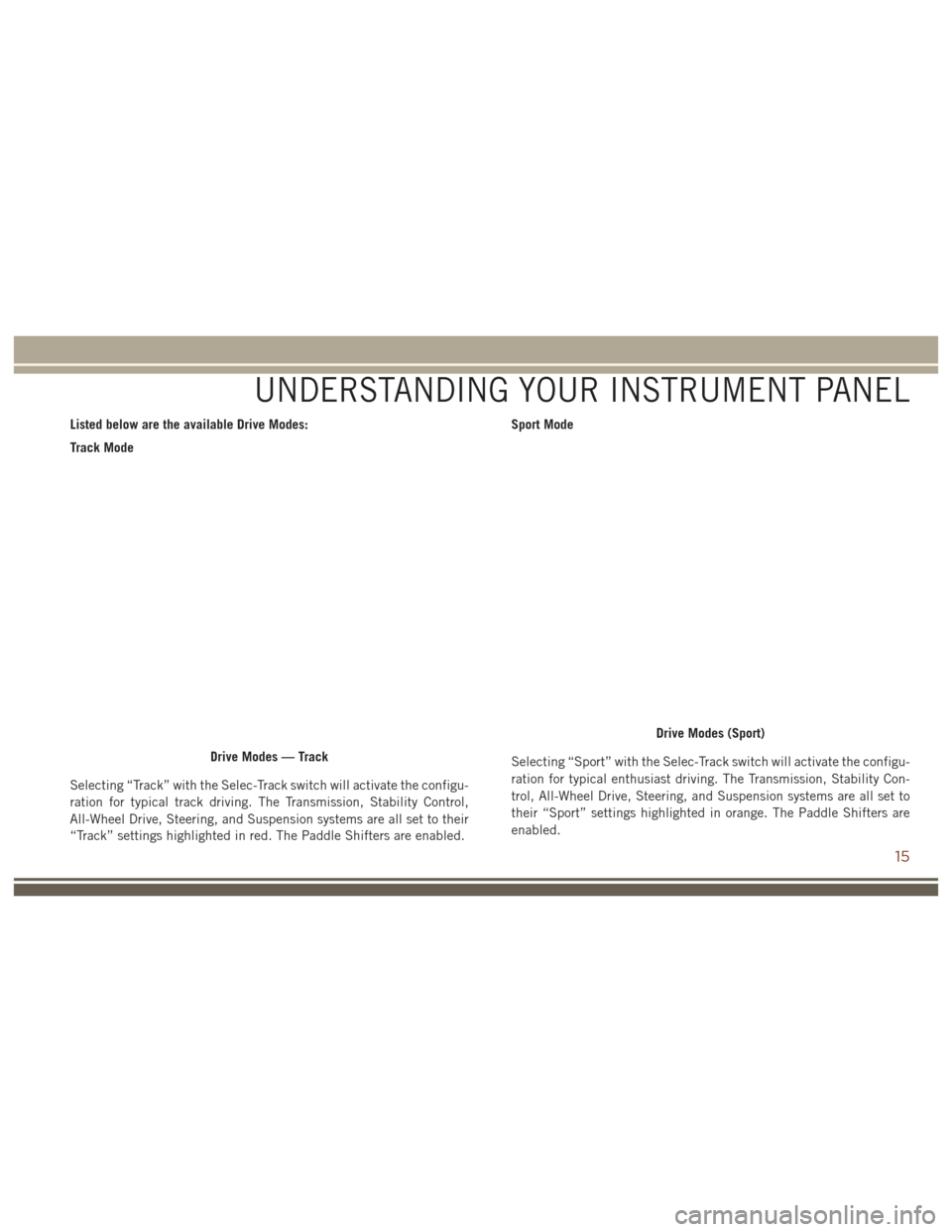
Listed below are the available Drive Modes:
Track Mode
Selecting “Track” with the Selec-Track switch will activate the configu-
ration for typical track driving. The Transmission, Stability Control,
All-Wheel Drive, Steering, and Suspension systems are all set to their
“Track” settings highlighted in red. The Paddle Shifters are enabled.Sport Mode
Selecting “Sport” with the Selec-Track switch will activate the configu-
ration for typical enthusiast driving. The Transmission, Stability Con-
trol, All-Wheel Drive, Steering, and Suspension systems are all set to
their “Sport” settings highlighted in orange. The Paddle Shifters are
enabled.
Drive Modes — Track
Drive Modes (Sport)
UNDERSTANDING YOUR INSTRUMENT PANEL
15
Page 18 of 44
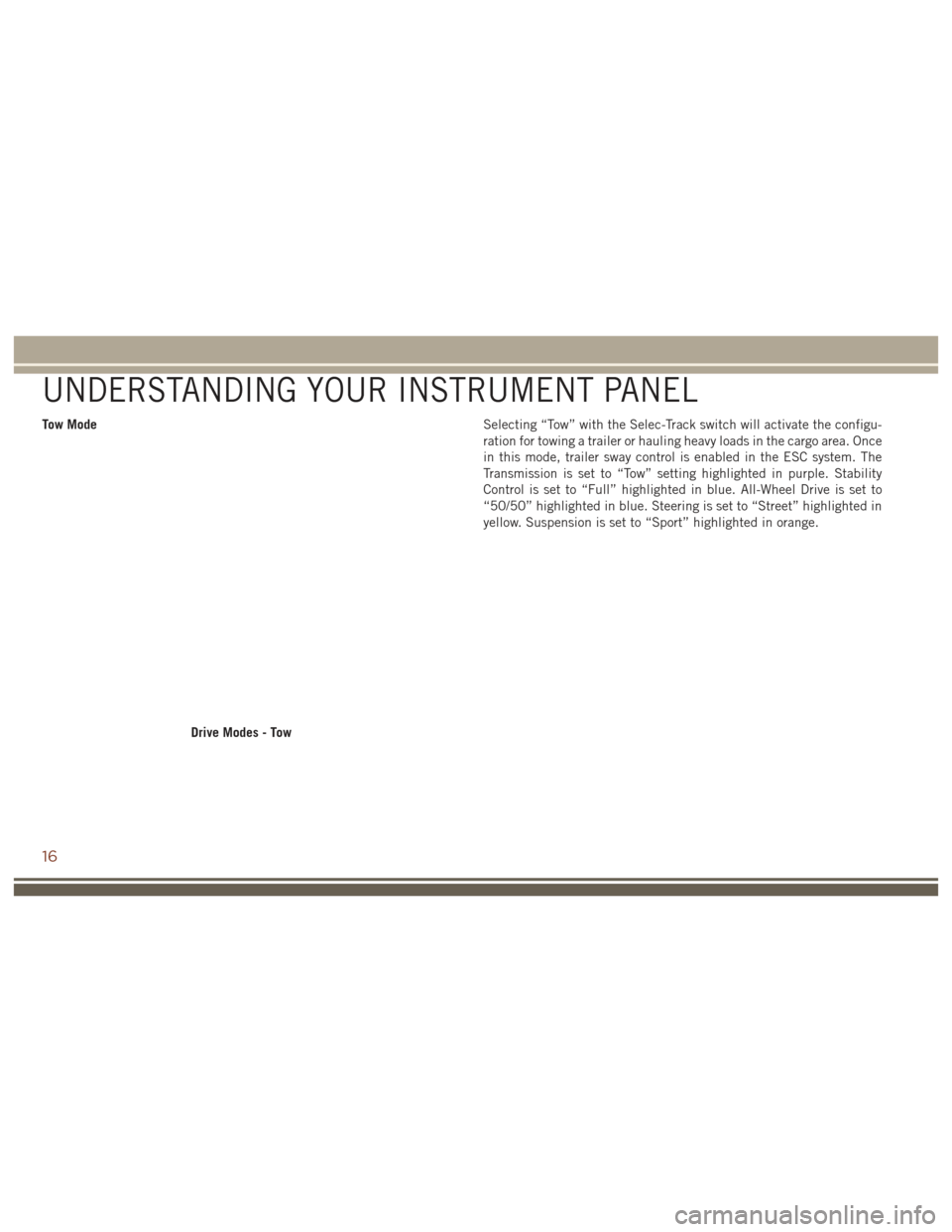
Tow ModeSelecting “Tow” with the Selec-Track switch will activate the configu-
ration for towing a trailer or hauling heavy loads in the cargo area. Once
in this mode, trailer sway control is enabled in the ESC system. The
Transmission is set to “Tow” setting highlighted in purple. Stability
Control is set to “Full” highlighted in blue. All-Wheel Drive is set to
“50/50” highlighted in blue. Steering is set to “Street” highlighted in
yellow. Suspension is set to “Sport” highlighted in orange.
Drive Modes - Tow
UNDERSTANDING YOUR INSTRUMENT PANEL
16
Page 19 of 44
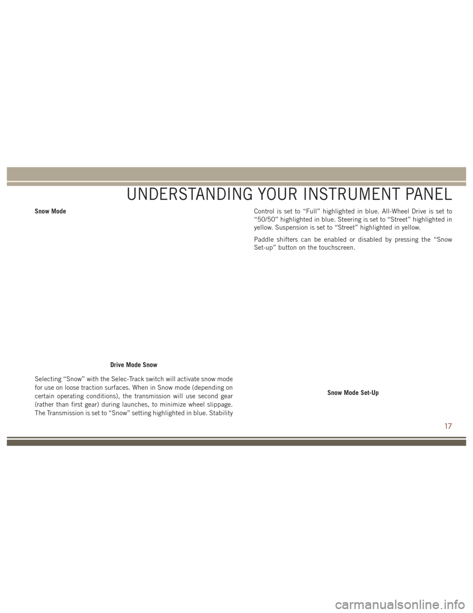
Snow Mode
Selecting “Snow” with the Selec-Track switch will activate snow mode
for use on loose traction surfaces. When in Snow mode (depending on
certain operating conditions), the transmission will use second gear
(rather than first gear) during launches, to minimize wheel slippage.
The Transmission is set to “Snow” setting highlighted in blue. StabilityControl is set to “Full” highlighted in blue. All-Wheel Drive is set to
“50/50” highlighted in blue. Steering is set to “Street” highlighted in
yellow. Suspension is set to “Street” highlighted in yellow.
Paddle shifters can be enabled or disabled by pressing the “Snow
Set-up” button on the touchscreen.
Drive Mode Snow
Snow Mode Set-Up
UNDERSTANDING YOUR INSTRUMENT PANEL
17
Page 20 of 44
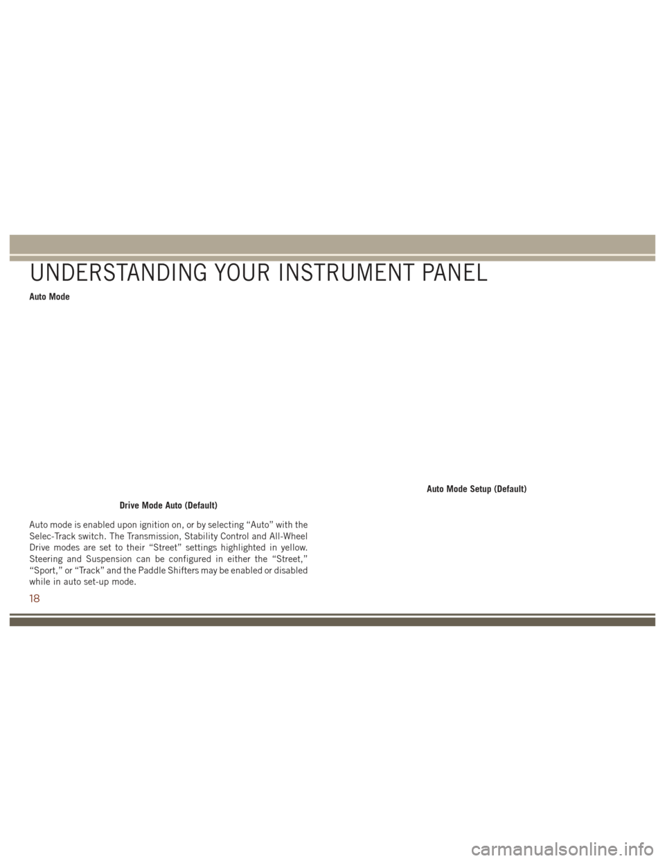
Auto Mode
Auto mode is enabled upon ignition on, or by selecting “Auto” with the
Selec-Track switch. The Transmission, Stability Control and All-Wheel
Drive modes are set to their “Street” settings highlighted in yellow.
Steering and Suspension can be configured in either the “Street,”
“Sport,” or “Track” and the Paddle Shifters may be enabled or disabled
while in auto set-up mode.
Drive Mode Auto (Default)
Auto Mode Setup (Default)
UNDERSTANDING YOUR INSTRUMENT PANEL
18
Page 21 of 44
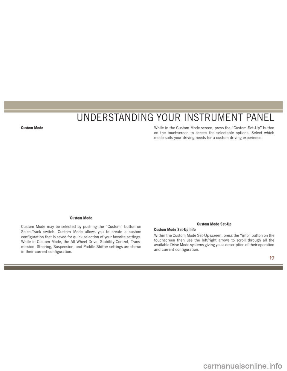
Custom Mode
Custom Mode may be selected by pushing the “Custom” button on
Selec-Track switch. Custom Mode allows you to create a custom
configuration that is saved for quick selection of your favorite settings.
While in Custom Mode, the All-Wheel Drive, Stability Control, Trans-
mission, Steering, Suspension, and Paddle Shifter settings are shown
in their current configuration.While in the Custom Mode screen, press the “Custom Set-Up” button
on the touchscreen to access the selectable options. Select which
mode suits your driving needs for a custom driving experience.
Custom Mode Set-Up Info
Within the Custom Mode Set-Up screen, press the “info” button on the
touchscreen then use the left/right arrows to scroll through all the
available Drive Mode systems giving you a description of their operation
and current configuration.
Custom Mode
Custom Mode Set-Up
UNDERSTANDING YOUR INSTRUMENT PANEL
19
Page 24 of 44
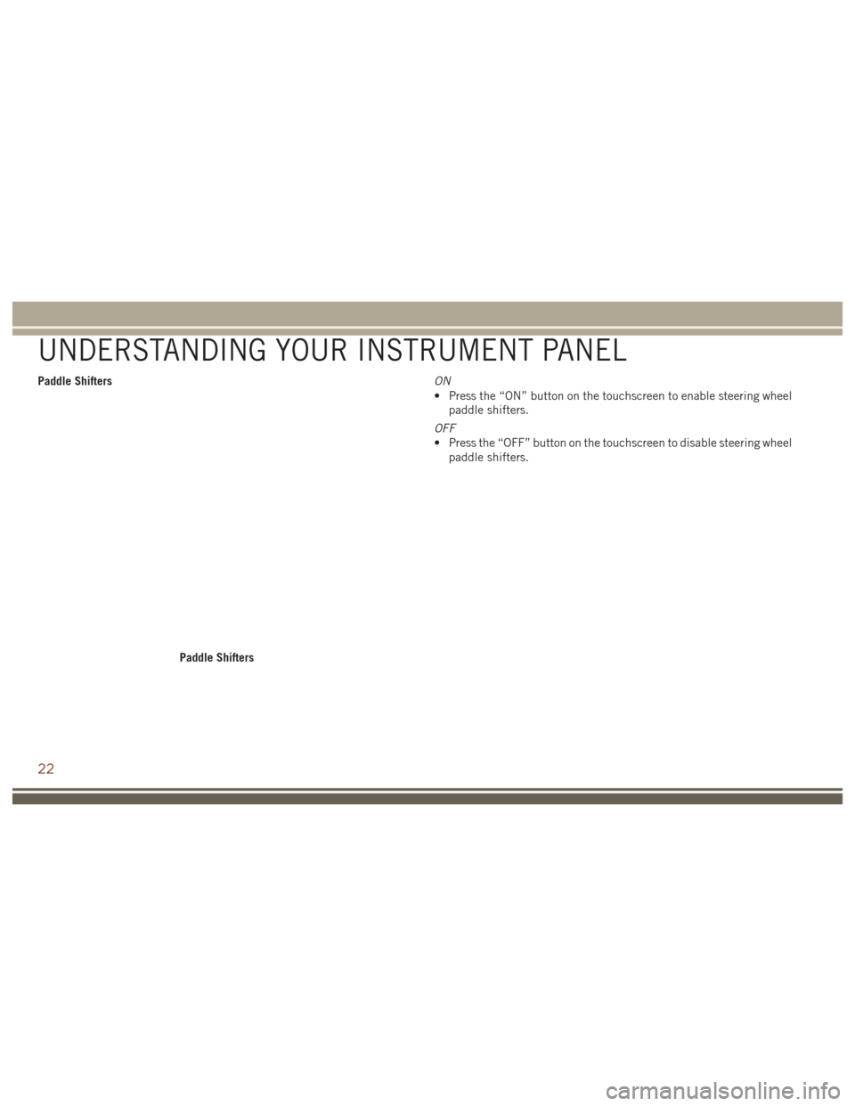
Paddle ShiftersON
• Press the “ON” button on the touchscreen to enable steering wheel
paddle shifters.
OFF
• Press the “OFF” button on the touchscreen to disable steering wheel paddle shifters.
Paddle Shifters
UNDERSTANDING YOUR INSTRUMENT PANEL
22
Page 32 of 44
While in Valet Mode the following vehicle configurations are set and
locked to prevent unauthorized modification:
• All-Wheel Drive is set to 50/50.
• Transmission locks out access to first gear and up-shifts earlier thannormal.
• Stability Control, Steering, and Suspension are set to their STREET settings.
• Steering wheel paddle shifters are disabled.
• The Drive Mode interface is not available. Pushing the SRT button on Selec-Track switch will display the unlock keypad.
• The ESC Off button is disabled.
• The Launch Control button is disabled.
• Engine limited to a lowest power output state.
To exit Valet Mode you must enter the same four digit PIN that was used
to enter the mode. The unlock keypad can be accessed by either
pushing the SRT button on Selec-Track switch, or pressing the “Valet”
button on the touchscreen.
Valet Mode Deactivation
UNDERSTANDING YOUR INSTRUMENT PANEL
30
Page 36 of 44
LAUNCH CONTROL — IF EQUIPPED
This vehicle is equipped with a Launch Control system that is designed
to allow the driver to achieve maximum vehicle acceleration in a
straight line. Launch Control is a form of traction control that manages
tire slip while launching the vehicle. This feature is intended for use
during race events on a closed course where consistent quarter mile
and zero to sixty times are desired. The system is not intended to
compensate for lack of driver experience or familiarity with the race
track. Use of this feature in low traction (cold, wet, gravel, etc.)
conditions may results in excess wheel slip outside this systems control
resulting in an aborted launch.
Preconditions:
• Launch Control should not be used on public roads. Always checktrack conditions and the surrounding area.
• Launch Control is not available within the first 500 miles (805 km) of engine break-in.
• Launch Control should only be used when the engine and transmis- sion are at operating temperature.
•
Launch Control is intended to be used on dry, paved road surfaces only.
CAUTION!
Use on slippery or loose surfaces may cause damage to vehicle
components and is not recommended. Launch Control is only available when the following procedure is
followed:
NOTE:
Pushing the SRT button on the Select-Track switch or pressing
the “Apps” button on the touchscreen are the two options to access
launch control features. Please refer to “SRT Drive Modes” in “Multi-
media” for further information.
1. Press the “Race Options” button on the touchscreen or push the LAUNCH button on the Select-Track switch.
2. Press the “Launch RPM Set-Up” button on the touchscreen. This screen will allow you to adjust your launch RPM’s for optimum
launch/traction.
3. Press the “Activate Launch Control” button on the touchscreen, follow instructions in the instrument cluster display.
• Make sure the vehicle is not moving.
• Put vehicle in first gear.
• Steering wheel must be pointing straight.
• Vehicle must be on level ground.
• Apply Brake Pressure.
• While holding the brake, rapidly apply the accelerator pedal to wide open throttle. The engine speed will hold at the RPM that
was set in the “Launch RPM Set-up” screen.
STARTING AND OPERATING
34