towing JEEP GRAND CHEROKEE 2017 WK2 / 4.G Owner's Manual
[x] Cancel search | Manufacturer: JEEP, Model Year: 2017, Model line: GRAND CHEROKEE, Model: JEEP GRAND CHEROKEE 2017 WK2 / 4.GPages: 372
Page 170 of 372
After the engine is turned off, it may be
noticed that the air suspension system oper-
ates briefly, this is normal. The system is
correcting the position of the vehicle to en-
sure a proper appearance.
To assist with changing a spare tire, the
Quadra-Lift air suspension system has a fea-
ture which allows the automatic leveling to
be disabled. Refer to “Uconnect Settings” in
“Multimedia” for further information.
NOTE:
If equipped with a touch screen radio all
enabling/disabling of air suspension features
must be done through the radio. Refer to
“Uconnect Settings” in “Multimedia” for fur-
ther information.
WARNING!
The air suspension system uses a high
pressure volume of air to operate the sys-
tem. To avoid personal injury or damage to
the system, see your authorized dealer for
service.
Air Suspension Modes
The Air Suspension system has multiple
modes to protect the system in unique situa-
tions:
Tire/Jack Mode
To assist with changing a spare tire, the air
suspension system has a feature which al-
lows the automatic leveling to be disabled.
Refer to “Uconnect Settings” in “Multime-
dia” for further information.
NOTE:
This mode is intended to be enabled with
engine running.
Transport Mode
To assist with flat bed towing, the air suspen-
sion system has a feature which will put the
vehicle into Entry/Exit height and disable the
automatic load leveling system. Refer to
“Uconnect Settings” in “Multimedia” for fur-
ther information.
NOTE:
This mode is intended to be enabled with
engine running.Wheel Alignment Mode
Before performing a wheel alignment this
mode must be enabled. Refer to “Uconnect
Settings” in “Multimedia” for further infor-
mation.
NOTE:
This mode is intended to be enabled with
engine running.
If equipped with a touch screen radio all
enabling/disabling of air suspension features
must be done through the radio. Refer to
“Uconnect Settings” in “Multimedia” for fur-
ther information.
Instrument Cluster Display Messages
When the appropriate conditions exist, a
message will appear in the instrument clus-
ter. Refer to “Instrument Cluster Display” in
“Getting To Know Your Instrument Panel” for
further information.
Operation
The indicator lamps 3 through 6 will illumi-
nate to show the current position of the
vehicle. Flashing indicator lamps will show a
position which the system is working to
STARTING AND OPERATING
168
Page 173 of 372
NOTE:
Activate the Hill Descent Control or Selec
Speed Control for steep downhill control. See
“Electronic Brake Control System” in this
section for further information.
Instrument Cluster Display Messages
When the appropriate conditions exist, a
message will appear in the instrument clus-
ter. Refer to “Instrument Cluster Display” in
“Getting To Know Your Instrument Panel” for
further information.
SELEC-TRACK — IF
EQUIPPED (SRT)
Description
Selec-Track combines the capabilities of the
vehicle control systems, along with driver
input, to provide the best performance for all
terrains.
Rotate the Selec-Track knob to select the
desired mode.Refer to “Drive Modes” in the “Multimedia”
section in your Owner’s Manual at
www.jeep.com/en/owners/manuals/ for fur-
ther information.
Selec-Track consists of the following posi-
tions:
•
Sport – Dry weather, on-road calibration.
Performance based tuning that provides a
rear wheel drive feel but with improved
handling and acceleration over a two-
wheel drive vehicle. This feature will reset
to AUTO on an ignition cycle.
• Snow – Tuning set for additional stability in
inclement weather. Use on and off road on
loose traction surfaces such as snow. This
feature will reset to AUTO upon an ignition
cycle. •
Auto – Fully automatic full time four-wheel
drive operation can be used on and off
road. Balances traction with seamless
steering feel to provide improved handling
and acceleration over two-wheel drive ve-
hicles.
• Track – Track road calibration for use on
high traction surfaces. Driveline is maxi-
mized for traction. Some binding may be
felt on less forgiving surfaces. This feature
will reset to AUTO on an ignition cycle.
• To w – Use this mode for towing and haul-
ing heavy loads. Vehicle suspension will go
to sport mode. Trailer sway control is en-
abled in the ESC system. This feature will
reset to AUTO upon an ignition cycle.
Custom
This mode allows the driver to create a cus-
tom vehicle configuration that is saved for
quick selection of favorite settings. The sys-
tem will return to AUTO mode when the
ignition switch is cycled from RUN to OFF to
RUN, if this mode is selected. While in Cus-
tom Mode the Stability, Transmission, Steer-
Selec-Track Switch
171
Page 180 of 372
• Pushing the normal (Fixed Speed) SPEEDCONTROL ON/OFF button will result in
turning ON (changing to) the normal
(Fixed Speed) Speed Control mode.
Refer to your Owner's Manual at
www.jeep.com/en/owners/manuals/ for fur-
ther information.
WARNING!
Adaptive Cruise Control (ACC) is a conve-
nience system. It is not a substitute for
active driving involvement. It is always the
driver’s responsibility to be attentive of
road, traffic, and weather conditions, ve-
hicle speed, distance to the vehicle ahead;
and, most importantly, brake operation to
ensure safe operation of the vehicle under
all road conditions. Your complete atten-
tion is always required while driving to
maintain safe control of your vehicle. Fail-
ure to follow these warnings can result in a
collision and death or serious personal
injury.
The ACC system:
• Does not react to pedestrians, oncoming vehicles, and stationary objects (e.g., a
WARNING!
stopped vehicle in a traffic jam or a
disabled vehicle).
• Cannot take street, traffic, and weather
conditions into account, and may be
limited upon adverse sight distance con-
ditions.
• Does not always fully recognize complex
driving conditions, which can result in
wrong or missing distance warnings.
• Will bring the vehicle to a complete stop
while following a target vehicle and hold
the vehicle for 2 seconds in the stop
position. If the target vehicle does not
start moving within two seconds the ACC
system will display a message that the
system will release the brakes and that
the brakes must be applied manually. An
audible chime will sound when the
brakes are released.
You should switch off the ACC system:
• When driving in fog, heavy rain, heavy
snow, sleet, heavy traffic, and complex
driving situations (i.e., in highway con-
struction zones).
WARNING!
• When entering a turn lane or highway offramp; when driving on roads that are
winding, icy, snow-covered, slippery, or
have steep uphill or downhill slopes.
• When towing a trailer up or down steep
slopes.
• When circumstances do not allow safe
driving at a constant speed.
The Cruise Control system has two control
modes:
• Adaptive Cruise Control mode for main-
taining an appropriate distance between
vehicles.
• Normal (fixed speed) electronic speed
control mode for cruising at a constant
preset speed. For additional informa-
tion, refer to “Normal (Fixed Speed)
Cruise Control Mode” in your Owner’s
Manual at
www.jeep.com/en/owners/manuals/
Normal (fixed speed) electronic speed con-
trol will not react to preceding vehicles. Al-
ways be aware of the mode selected.
You can change the mode by using the
Cruise Control buttons. The two control
STARTING AND OPERATING
178
Page 182 of 372
• Clean the ParkSense sensors regularly,taking care not to scratch or damage them.
The sensors must not be covered with ice,
snow, slush, mud, dirt or debris. Failure to
do so can result in the system not working
properly. The ParkSense system might not
detect an obstacle behind the fascia/
bumper, or it could provide a false indica-
tion that an obstacle is behind the fascia/
bumper.
• Use the ParkSense switch to turn the ParkSense system OFF if objects such as
bicycle carriers, trailer hitches, etc. are
placed within 12 in (30 cm) from the rear
fascia/bumper. Failure to do so can result
in the system misinterpreting a close ob-
ject as a sensor problem, causing the
“PARKSENSE UNAVAILABLE SERVICE
REQUIRED” message to appear in the
instrument cluster display.
• ParkSense should be disabled when the liftgate is in the open position and the
vehicle is in REVERSE. An open liftgate
could provide a false indication that an
obstacle is behind the vehicle.WARNING!
• Drivers must be careful when backing upeven when using ParkSense. Always
check carefully behind your vehicle,
look behind you, and be sure to check
for pedestrians, animals, other vehicles,
obstructions, and blind spots before
backing up. You are responsible for
safety and must continue to pay atten-
tion to your surroundings. Failure to do
so can result in serious injury or death.
• Before using ParkSense, it is strongly
recommended that the ball mount and
hitch ball assembly is disconnected
from the vehicle when the vehicle is not
used for towing. Failure to do so can
result in injury or damage to vehicles or
obstacles because the hitch ball will be
much closer to the obstacle than the
rear fascia when the loudspeaker sounds
the continuous tone. Also, the sensors
could detect the ball mount and hitch
ball assembly, depending on its size and
shape, giving a false indication that an
obstacle is behind the vehicle.
CAUTION!
• ParkSense is only a parking aid and it isunable to recognize every obstacle, in-
cluding small obstacles. Parking curbs
might be temporarily detected or not
detected at all. Obstacles located above
or below the sensors will not be detected
when they are in close proximity.
• The vehicle must be driven slowly when
using ParkSense in order to be able to
stop in time when an obstacle is de-
tected. It is recommended that the
driver looks over his/her shoulder when
using ParkSense.
PARKSENSE FRONT AND
REAR PARK ASSIST
Sensors
The four ParkSense sensors, located in the
rear fascia/bumper, monitor the area behind
the vehicle that is within the sensors field of
view. The sensors can detect obstacles from
approximately 12 inches (30 cm) up to
STARTING AND OPERATING
180
Page 195 of 372
CAUTION!
• Never add anything other than DEF tothe tank – especially any form of hydro-
carbon such as diesel fuel, fuel system
additives, gasoline, or any other
petroleum-based product. Even a very
small amount of these, less than
100 parts per million or less than 1 oz.
per 78 gallons (295 liters) will contami-
nate the entire DEF system and will
require replacement. If owners use a
container, funnel or nozzle when refilling
the tank, it should either be new or one
that is has only been used for adding
DEF. MOPAR provides an attachable
nozzle with its DEF for this purpose. 3. Stop filling the DEF tank immediately
when any of the following happen: DEF
stops flowing from the fill bottle into the
DEF fill inlet, DEF splashes out the fill
inlet, or a DEF pump nozzle automatically
shuts off.
4. Reinstall cap onto DEF fill inlet.
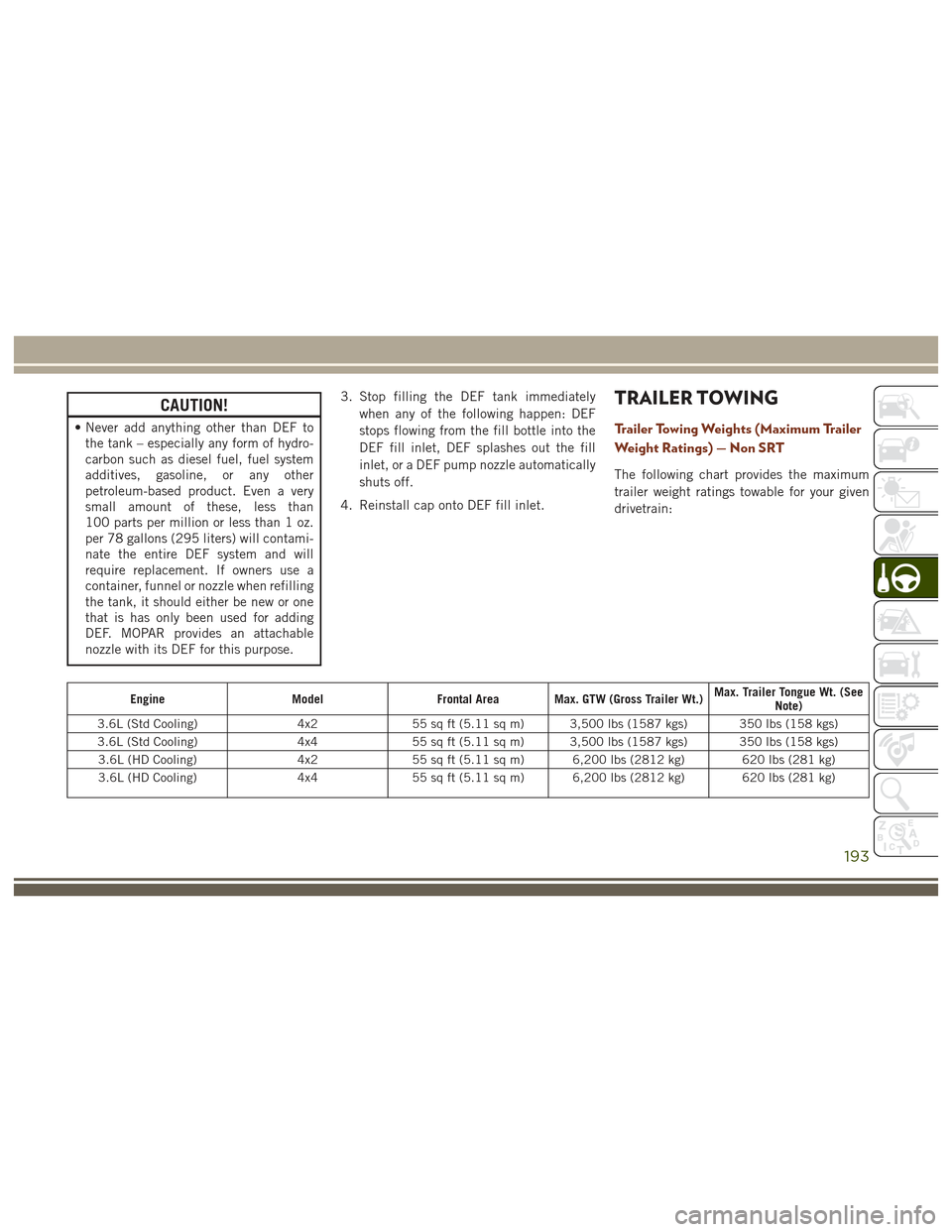
TRAILER TOWING
Trailer Towing Weights (Maximum Trailer
Weight Ratings) — Non SRT
The following chart provides the maximum
trailer weight ratings towable for your given
drivetrain:
Engine ModelFrontal Area Max. GTW (Gross Trailer Wt.) Max. Trailer Tongue Wt. (See
Note)
3.6L (Std Cooling) 4x255 sq ft (5.11 sq m) 3,500 lbs (1587 kgs) 350 lbs (158 kgs)
3.6L (Std Cooling) 4x455 sq ft (5.11 sq m) 3,500 lbs (1587 kgs) 350 lbs (158 kgs)
3.6L (HD Cooling) 4x255 sq ft (5.11 sq m) 6,200 lbs (2812 kg) 620 lbs (281 kg)
3.6L (HD Cooling) 4x455 sq ft (5.11 sq m) 6,200 lbs (2812 kg) 620 lbs (281 kg)
193
Page 196 of 372
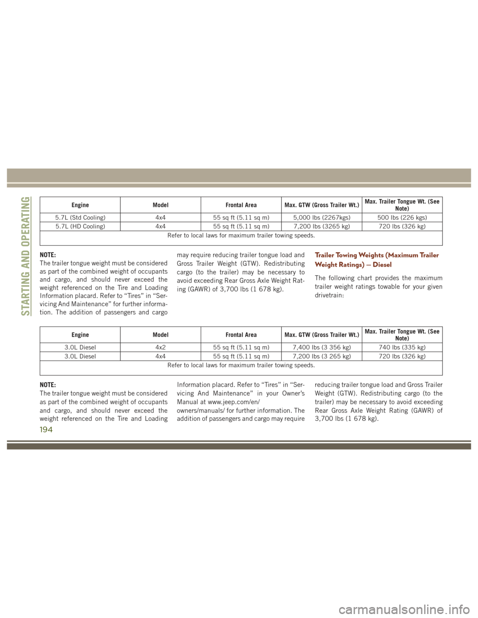
EngineModelFrontal Area Max. GTW (Gross Trailer Wt.) Max. Trailer Tongue Wt. (See
Note)
5.7L (Std Cooling) 4x455 sq ft (5.11 sq m) 5,000 lbs (2267kgs) 500 lbs (226 kgs)
5.7L (HD Cooling) 4x455 sq ft (5.11 sq m) 7,200 lbs (3265 kg) 720 lbs (326 kg)
Refer to local laws for maximum trailer towing speeds.
NOTE:
The trailer tongue weight must be considered
as part of the combined weight of occupants
and cargo, and should never exceed the
weight referenced on the Tire and Loading
Information placard. Refer to “Tires” in “Ser-
vicing And Maintenance” for further informa-
tion. The addition of passengers and cargo may require reducing trailer tongue load and
Gross Trailer Weight (GTW). Redistributing
cargo (to the trailer) may be necessary to
avoid exceeding Rear Gross Axle Weight Rat-
ing (GAWR) of 3,700 lbs (1 678 kg).Trailer Towing Weights (Maximum Trailer
Weight Ratings) — Diesel
The following chart provides the maximum
trailer weight ratings towable for your given
drivetrain:
Engine
ModelFrontal Area Max. GTW (Gross Trailer Wt.) Max. Trailer Tongue Wt. (See
Note)
3.0L Diesel 4x255 sq ft (5.11 sq m) 7,400 lbs (3 356 kg) 740 lbs (335 kg)
3.0L Diesel 4x455 sq ft (5.11 sq m) 7,200 lbs (3 265 kg) 720 lbs (326 kg)
Refer to local laws for maximum trailer towing speeds.
NOTE:
The trailer tongue weight must be considered
as part of the combined weight of occupants
and cargo, and should never exceed the
weight referenced on the Tire and Loading Information placard. Refer to “Tires” in “Ser-
vicing And Maintenance” in your Owner’s
Manual at www.jeep.com/en/
owners/manuals/ for further information. The
addition of passengers and cargo may require reducing trailer tongue load and Gross Trailer
Weight (GTW). Redistributing cargo (to the
trailer) may be necessary to avoid exceeding
Rear Gross Axle Weight Rating (GAWR) of
3,700 lbs (1 678 kg).
STARTING AND OPERATING
194
Page 197 of 372
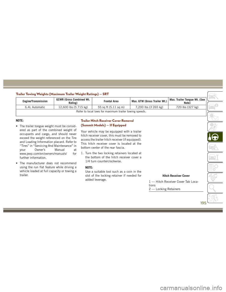
Trailer Towing Weights (Maximum Trailer Weight Ratings) — SRT
Engine/TransmissionGCWR (Gross Combined Wt.
Rating) Frontal Area Max. GTW (Gross Trailer Wt.) Max. Trailer Tongue Wt. (See
Note)
6.4L Automatic 12,600 lbs (5 715 kg) 55 sq ft (5.11 sq m) 7,200 lbs (3 265 kg) 720 lbs (327 kg) Refer to local laws for maximum trailer towing speeds.
NOTE:
• The trailer tongue weight must be consid-ered as part of the combined weight of
occupants and cargo, and should never
exceed the weight referenced on the Tire
and Loading Information placard. Refer to
“Tires” in “Servicing And Maintenance” in
your Owner’s Manual at
www.jeep.com/en/owners/manuals/ for
further information.
• The manufacturer does not recommend using the run flat feature while driving a
vehicle loaded at full capacity or towing a
trailer.Trailer Hitch Receiver Cover Removal
(Summit Models) — If Equipped
Your vehicle may be equipped with a trailer
hitch receiver cover, this must be removed to
access the trailer hitch receiver (if equipped).
This hitch receiver cover is located at the
bottom center of the rear fascia.
1. Turn the two locking retainers located at
the bottom of the hitch receiver cover a
1/4 turn counterclockwise.
NOTE:
Use a suitable tool such as a coin in the
slot of the locking retainer if needed for
added leverage.
Hitch Receiver Cover
1 — Hitch Receiver Cover Tab Loca-
tions
2 — Locking Retainers
195
Page 198 of 372
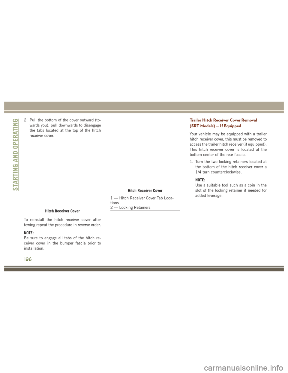
2. Pull the bottom of the cover outward (to-wards you), pull downwards to disengage
the tabs located at the top of the hitch
receiver cover.
To reinstall the hitch receiver cover after
towing repeat the procedure in reverse order.
NOTE:
Be sure to engage all tabs of the hitch re-
ceiver cover in the bumper fascia prior to
installation.Trailer Hitch Receiver Cover Removal
(SRT Models) — If Equipped
Your vehicle may be equipped with a trailer
hitch receiver cover, this must be removed to
access the trailer hitch receiver (if equipped).
This hitch receiver cover is located at the
bottom center of the rear fascia.
1. Turn the two locking retainers located at the bottom of the hitch receiver cover a
1/4 turn counterclockwise.
NOTE:
Use a suitable tool such as a coin in the
slot of the locking retainer if needed for
added leverage.
Hitch Receiver Cover
Hitch Receiver Cover
1 — Hitch Receiver Cover Tab Loca-
tions
2 — Locking Retainers
STARTING AND OPERATING
196
Page 200 of 372
To reinstall the hitch receiver cover after
towing repeat the procedure in reverse order.NOTE:
Be sure to engage all tabs of the hitch re-
ceiver cover in the bumper fascia prior to
installation.
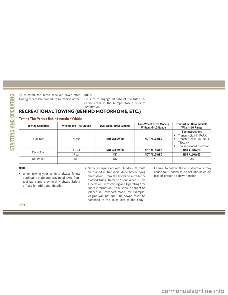
RECREATIONAL TOWING (BEHIND MOTORHOME, ETC.)
Towing This Vehicle Behind Another Vehicle
Towing Condition Wheels OFF The Ground Two-Wheel Drive Models
Four-Wheel Drive Models
Without 4–LO Range Four-Wheel Drive Models
With 4–LO Range
Flat Tow NONENOT ALLOWED
NOT ALLOWEDSee Instructions
• Transmission in PARK
• Transfer case in NEU-
TRAL (N)
• Tow in forward direction
Dolly Tow Front
NOT ALLOWED
NOT ALLOWEDNOT ALLOWED
Rear OKNOT ALLOWED
NOT ALLOWED
On Trailer ALLOKOKOK
NOTE:
• When towing your vehicle, always follow
applicable state and provincial laws. Con-
tact state and provincial Highway Safety
offices for additional details. • Vehicles equipped with Quadra-Lift must
be placed in Transport Mode before tying
them down (from the body) on a trailer or
flatbed truck. Refer to “Four Wheel Drive
Operation” in “Starting and Operating” for
more information. If the vehicle cannot be
placed in Transport mode (for example,
engine will not run), tie-downs must be
fastened to the axles (not to the body). Failure to follow these instructions may
cause fault codes to be set and/or cause
loss of proper tie-down tension.
STARTING AND OPERATING
198
Page 201 of 372
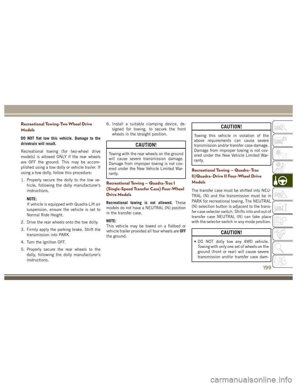
Recreational Towing-Two Wheel Drive
Models
DO NOT flat tow this vehicle. Damage to the
drivetrain will result.
Recreational towing (for two-wheel drive
models) is allowed ONLY if the rear wheels
are OFF the ground. This may be accom-
plished using a tow dolly or vehicle trailer. If
using a tow dolly, follow this procedure:
1. Properly secure the dolly to the tow ve-hicle, following the dolly manufacturer's
instructions.
NOTE:
If vehicle is equipped with Quadra-Lift air
suspension, ensure the vehicle is set to
Normal Ride Height.
2. Drive the rear wheels onto the tow dolly.
3. Firmly apply the parking brake. Shift the transmission into PARK.
4. Turn the ignition OFF.
5. Properly secure the rear wheels to the dolly, following the dolly manufacturer’s
instructions. 6. Install a suitable clamping device, de-
signed for towing, to secure the front
wheels in the straight position.
CAUTION!
Towing with the rear wheels on the ground
will cause severe transmission damage.
Damage from improper towing is not cov-
ered under the New Vehicle Limited War-
ranty.
Recreational Towing — Quadra-Trac I
(Single-Speed Transfer Case) Four-Wheel
Drive Models
Recreational towing is not allowed. These
models do not have a NEUTRAL (N) position
in the transfer case.
NOTE:
This vehicle may be towed on a flatbed or
vehicle trailer provided all four wheels are OFF
the ground.
CAUTION!
Towing this vehicle in violation of the
above requirements can cause severe
transmission and/or transfer case damage.
Damage from improper towing is not cov-
ered under the New Vehicle Limited War-
ranty.
Recreational Towing — Quadra–Trac
II/Quadra–Drive II Four-Wheel Drive
Models
The transfer case must be shifted into NEU-
TRAL (N) and the transmission must be in
PARK for recreational towing. The NEUTRAL
(N) selection button is adjacent to the trans-
fer case selector switch. Shifts into and out of
transfer case NEUTRAL (N) can take place
with the selector switch in any mode position.
CAUTION!
• DO NOT dolly tow any 4WD vehicle. Towing with only one set of wheels on the
ground (front or rear) will cause severe
transmission and/or transfer case dam-
199