turn signal JEEP GRAND CHEROKEE 2017 WK2 / 4.G Owner's Manual
[x] Cancel search | Manufacturer: JEEP, Model Year: 2017, Model line: GRAND CHEROKEE, Model: JEEP GRAND CHEROKEE 2017 WK2 / 4.GPages: 372
Page 112 of 372
is then followed by a graphic display, with “-
-“ in place of the pressure value(s), indicat-
ing which Tire Pressure Monitoring Sensor(s)
is not being received.
If the ignition switch is cycled, this sequence
will repeat, providing the system fault still
exists. If the system fault no longer exists, the
Tire Pressure Monitoring Telltale Light will no
longer flash, the "SERVICE TPM SYSTEM"
message will not be present, and a pressure
value will be displayed instead of dashes. A
system fault can occur by any of the follow-
ing:
• Jamming due to electronic devices or driv-ing next to facilities emitting the same
Radio Frequencies as the TPM sensors.
• Installing some form of aftermarket win- dow tinting that affects radio wave signals.
• Lots of snow or ice around the wheels or wheel housings.
• Using tire chains on the vehicle.
• Using wheels/tires not equipped with TPM sensors. NOTE:
There is no tire pressure monitoring sensor in
the spare tire. The TPMS will not be able to
monitor the tire pressure. If you install the
spare tire in place of a road tire that has a
pressure below the low-pressure warning
limit, upon the next ignition switch cycle, the
Tire Pressure Monitoring Telltale Light will
remain ON, a chime will sound, and the
instrument cluster display will still display a
pressure value in the different color graphic
display and an "Inflate to XXX kPa" message
will be displayed. After driving the vehicle for
up to 20 minutes above 15 mph (24 km/h),
the Tire Pressure Monitoring Telltale Light
will flash on and off for 75 seconds and then
remain on solid. In addition, the instrument
cluster display will display a “SERVICE TPM
SYSTEM" message for five seconds and then
display dashes (- -) in place of the pressure
value. For each subsequent ignition switch
cycle, a chime will sound, the Tire Pressure
Monitoring Telltale Light will flash on and off
for 75 seconds and then remain on solid, and
the instrument cluster display will display a
"SERVICE TPM SYSTEM" message for five
seconds and then display dashes (- -) in place of the pressure value. Once you repair or
replace the original road tire, and reinstall it
on the vehicle in place of the spare tire, the
TPMS will update automatically.
In addition, the Tire Pressure Monitoring Tell-
tale Light will turn OFF and the graphic in the
instrument cluster display will display a new
pressure value instead of dashes (- -), as long
as no tire pressure is below the low-pressure
warning limit in any of the four active road
tires. The vehicle may need to be driven for
up to 20 minutes above 15 mph (24 km/h) in
order for the TPMS to receive this informa-
tion.
TPMS Deactivation — If Equipped
The TPMS can be deactivated if replacing all
four wheel and tire assemblies (road tires)
with wheel and tire assemblies that do not
have TPMS Sensors, such as when installing
winter wheel and tire assemblies on your
vehicle.
To deactivate the TPMS, first, replace all four
wheel and tire assemblies (road tires) with
tires not equipped with Tire Pressure Moni-
toring (TPM) Sensors. Then, drive the vehicle
SAFETY
110
Page 115 of 372
Initial Indication
If the driver is unbuckled when the ignition
switch is first in the START or ON/RUN posi-
tion, a chime will signal for a few seconds. If
the driver or outboard front seat passenger (if
equipped with outboard front passenger seat
BeltAlert) is unbuckled when the ignition
switch is first in the START or ON/RUN posi-
tion the Seat Belt Reminder Light will turn on
and remain on until both outboard front seat
belts are buckled. The outboard front passen-
ger seat BeltAlert is not active when an out-
board front passenger seat is unoccupied.
BeltAlert Warning Sequence
The BeltAlert warning sequence is activated
when the vehicle is moving above a specified
vehicle speed range and the driver or out-
board front seat passenger is unbuckled (if
equipped with outboard front passenger seat
BeltAlert) (the outboard front passenger seat
BeltAlert is not active when the outboard
front passenger seat is unoccupied). The
BeltAlert warning sequence starts by blinking
the Seat Belt Reminder Light and sounding
an intermittent chime. Once the BeltAlert
warning sequence has completed, the SeatBelt Reminder Light will remain on until the
seat belts are buckled. The BeltAlert warning
sequence may repeat based on vehicle speed
until the driver and occupied outboard front
seat passenger seat belts are buckled. The
driver should instruct all occupants to buckle
their seat belts.
Change Of Status
If the driver or outboard front seat passenger
(if equipped with outboard front passenger
seat BeltAlert) unbuckles their seat belt while
the vehicle is traveling, the BeltAlert warning
sequence will begin until the seat belts are
buckled again. The outboard front passenger
seat BeltAlert is not active when the outboard
front passenger seat is unoccupied. BeltAlert
may be triggered when an animal or other
items are placed on the outboard front pas-
senger seat or when the seat is folded flat (if
equipped). It is recommended that pets be
restrained in the rear seat (if equipped) in pet
harnesses or pet carriers that are secured by
seat belts, and cargo is properly stowed.
BeltAlert can be activated or deactivated by
your authorized dealer. FCA US LLC does not
recommend deactivating BeltAlert.NOTE:
If BeltAlert has been deactivated and the
driver or outboard front seat passenger (if
equipped with outboard front passenger seat
BeltAlert) is unbuckled the Seat Belt Re-
minder Light will turn on and remain on until
the driver and outboard front seat passenger
seat belts are buckled.
Lap/Shoulder Belts
All seating positions in your vehicle are
equipped with lap/shoulder belts.
The seat belt webbing retractor will lock only
during very sudden stops or collisions. This
feature allows the shoulder part of the seat
belt to move freely with you under normal
conditions. However, in a collision the seat
belt will lock and reduce your risk of striking
the inside of the vehicle or being thrown out
of the vehicle.
WARNING!
• Relying on the air bags alone could lead
to more severe injuries in a collision. The
air bags work with your seat belt to
113
Page 147 of 372
WARNING!
clutch pedal (if present) to check for
interference. If your floor mat interferes
with the operation of any pedal, or is not
secure to the floor, remove the floor mat
from the vehicle and place the floor mat
in your trunk.
• ONLY use the passenger’s side floor mat
on the passenger’s side floor area.
• ALWAYS make sure objects cannot fall
or slide into the driver’s side floor area
when the vehicle is moving. Objects can
become trapped under accelerator,
brake, or clutch pedals and could cause
a loss of vehicle control.
• NEVER place any objects under the floor
mat (e.g., towels, keys, etc.). These ob-
jects could change the position of the
floor mat and may cause interference
with the accelerator, brake, or clutch
pedals.
• If the vehicle carpet has been removed
and re-installed, always properly attach
WARNING!
carpet to the floor and check the floor
mat fasteners are secure to the vehicle
carpet. Fully depress each pedal to
check for interference with the accelera-
tor, brake, or clutch pedals then re-
install the floor mats.
• It is recommended to only use mild soap
and water to clean your floor mats. After
cleaning, always check your floor mat
has been properly installed and is se-
cured to your vehicle using the floor mat
fasteners by lightly pulling mat.
Periodic Safety Checks You Should Make
Outside The Vehicle
Tires
Examine tires for excessive tread wear and
uneven wear patterns. Check for stones,
nails, glass, or other objects lodged in the
tread or sidewall. Inspect the tread for cuts and cracks. Inspect sidewalls for cuts,
cracks, and bulges. Check the wheel nuts for
tightness. Check the tires (including spare)
for proper cold inflation pressure.
Lights
Have someone observe the operation of brake
lights and exterior lights while you work the
controls. Check turn signal and high beam
indicator lights on the instrument panel.
Door Latches
Check for proper closing, latching, and lock-
ing.
Fluid Leaks
Check area under vehicle after overnight
parking for fuel, engine coolant, oil, or other
fluid leaks. Also, if gasoline fumes are de-
tected or if fuel, power steering fluid (if
equipped), or brake fluid leaks are sus-
pected. The cause should be located and
corrected immediately.
145
Page 185 of 372
To enable the ParkSense Active Park Assist
system, push the ParkSense Active Park As-
sist switch once (LED turns on).
To disable the ParkSense Active Park Assist
system, push the ParkSense Active Park As-
sist switch again (LED turns off).
When the ParkSense Active Park Assist sys-
tem is enabled the “Active ParkSense
Searching - Push OK to Switch to Perpen-
dicular” message will appear in the instru-
ment cluster display. You may switch to per-
pendicular parking if you desire. Push the OKbutton on the left side steering wheel switch
to change your parking space setting. You
may switch back to parallel parking if you
desire.
Refer to your Owner's Manual at
www.jeep.com/en/owners/manuals/ for fur-
ther information.
LANESENSE
LaneSense Operation
The LaneSense system is operational at
speeds above 37 mph (60 km/h) and below
112 mph (180 km/h). The LaneSense system
uses a forward looking camera to detect lane
markings and measure vehicle position
within the lane boundaries.
When both lane markings are detected and
the driver unintentionally drifts out of the
lane (no turn signal applied), the LaneSense
system provides a haptic warning in the form
of torque applied to the steering wheel to
prompt the driver to remain within the lane
boundaries. If the driver continues to unin-
tentionally drift out of the lane, the La-neSense system provides a visual warning
through the instrument cluster display to
prompt the driver to remain within the lane
boundaries.
The driver may manually override the haptic
warning by applying torque into the steering
wheel at any time.
When only a single lane marking is detected
and the driver unintentionally drifts across
the lane marking (no turn signal applied), the
LaneSense system provides a visual warning
through the instrument cluster display to
prompt the driver to remain within the lane.
When only a single lane marking is detected,
a haptic (torque) warning will not be pro-
vided.
NOTE:
When operating conditions have been met,
the LaneSense system will monitor if the
driver’s hands are on the steering wheel and
provides an audible warning to the driver
when the driver’s hands are not detected on
the steering wheel. The system will cancel if
the driver does not return their hands to the
wheel.
ParkSense Active Park Assist Switch Lo-
cation
183
Page 187 of 372
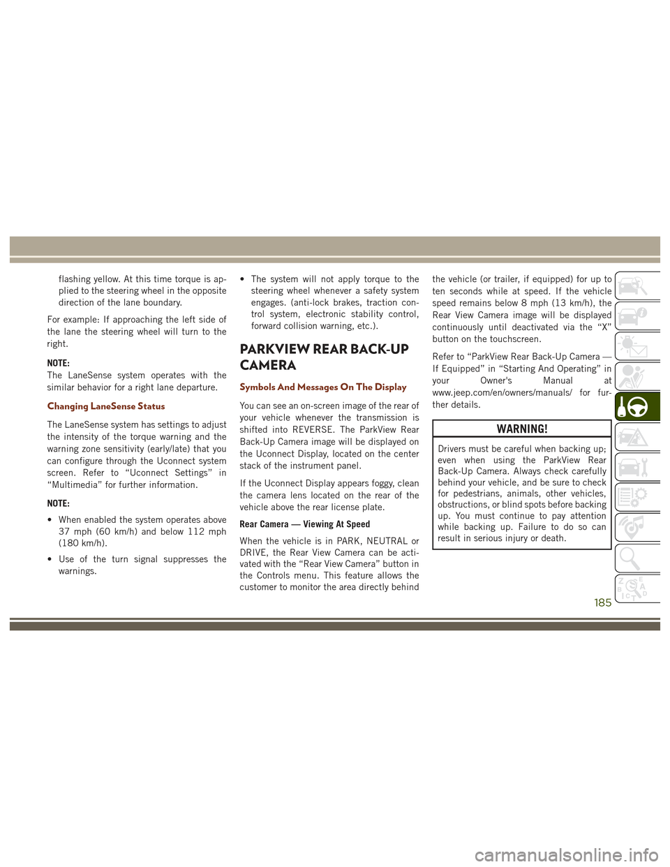
flashing yellow. At this time torque is ap-
plied to the steering wheel in the opposite
direction of the lane boundary.
For example: If approaching the left side of
the lane the steering wheel will turn to the
right.
NOTE:
The LaneSense system operates with the
similar behavior for a right lane departure.
Changing LaneSense Status
The LaneSense system has settings to adjust
the intensity of the torque warning and the
warning zone sensitivity (early/late) that you
can configure through the Uconnect system
screen. Refer to “Uconnect Settings” in
“Multimedia” for further information.
NOTE:
• When enabled the system operates above 37 mph (60 km/h) and below 112 mph
(180 km/h).
• Use of the turn signal suppresses the warnings. • The system will not apply torque to the
steering wheel whenever a safety system
engages. (anti-lock brakes, traction con-
trol system, electronic stability control,
forward collision warning, etc.).
PARKVIEW REAR BACK-UP
CAMERA
Symbols And Messages On The Display
You can see an on-screen image of the rear of
your vehicle whenever the transmission is
shifted into REVERSE. The ParkView Rear
Back-Up Camera image will be displayed on
the Uconnect Display, located on the center
stack of the instrument panel.
If the Uconnect Display appears foggy, clean
the camera lens located on the rear of the
vehicle above the rear license plate.
Rear Camera — Viewing At Speed
When the vehicle is in PARK, NEUTRAL or
DRIVE, the Rear View Camera can be acti-
vated with the “Rear View Camera” button in
the Controls menu. This feature allows the
customer to monitor the area directly behind the vehicle (or trailer, if equipped) for up to
ten seconds while at speed. If the vehicle
speed remains below 8 mph (13 km/h), the
Rear View Camera image will be displayed
continuously until deactivated via the “X”
button on the touchscreen.
Refer to “ParkView Rear Back-Up Camera —
If Equipped” in “Starting And Operating” in
your Owner's Manual at
www.jeep.com/en/owners/manuals/ for fur-
ther details.
WARNING!
Drivers must be careful when backing up;
even when using the ParkView Rear
Back-Up Camera. Always check carefully
behind your vehicle, and be sure to check
for pedestrians, animals, other vehicles,
obstructions, or blind spots before backing
up. You must continue to pay attention
while backing up. Failure to do so can
result in serious injury or death.
185
Page 206 of 372
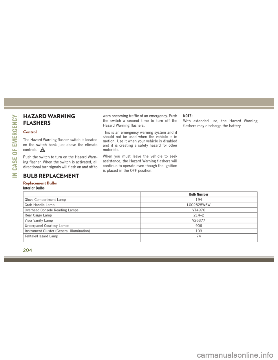
HAZARD WARNING
FLASHERS
Control
The Hazard Warning flasher switch is located
on the switch bank just above the climate
controls.
Push the switch to turn on the Hazard Warn-
ing flasher. When the switch is activated, all
directional turn signals will flash on and off towarn oncoming traffic of an emergency. Push
the switch a second time to turn off the
Hazard Warning flashers.
This is an emergency warning system and it
should not be used when the vehicle is in
motion. Use it when your vehicle is disabled
and it is creating a safety hazard for other
motorists.
When you must leave the vehicle to seek
assistance, the Hazard Warning flashers will
continue to operate even though the ignition
is placed in the OFF position. NOTE:
With extended use, the Hazard Warning
flashers may discharge the battery.
BULB REPLACEMENT
Replacement Bulbs
Interior Bulbs
Bulb Number
Glove Compartment Lamp 194
Grab Handle Lamp L002825W5W
Overhead Console Reading Lamps VT4976
Rear Cargo Lamp 214–2
Visor Vanity Lamp V26377
Underpanel Courtesy Lamps 906
Instrument Cluster (General Illumination) 103
Telltale/Hazard Lamp 74
IN CASE OF EMERGENCY
204
Page 207 of 372
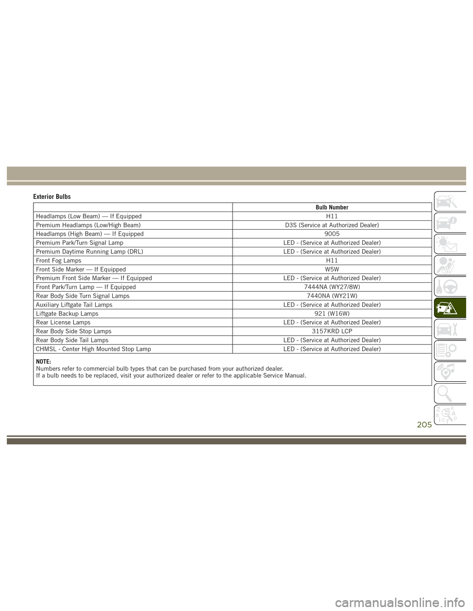
Exterior Bulbs
Bulb Number
Headlamps (Low Beam) — If Equipped H11
Premium Headlamps (Low/High Beam) D3S (Service at Authorized Dealer)
Headlamps (High Beam) — If Equipped 9005
Premium Park/Turn Signal Lamp LED - (Service at Authorized Dealer)
Premium Daytime Running Lamp (DRL) LED - (Service at Authorized Dealer)
Front Fog Lamps H11
Front Side Marker — If Equipped W5W
Premium Front Side Marker — If Equipped LED - (Service at Authorized Dealer)
Front Park/Turn Lamp — If Equipped 7444NA (WY27/8W)
Rear Body Side Turn Signal Lamps 7440NA (WY21W)
Auxiliary Liftgate Tail Lamps LED - (Service at Authorized Dealer)
Liftgate Backup Lamps 921 (W16W)
Rear License Lamps LED - (Service at Authorized Dealer)
Rear Body Side Stop Lamps 3157KRD LCP
Rear Body Side Tail Lamps LED - (Service at Authorized Dealer)
CHMSL - Center High Mounted Stop Lamp LED - (Service at Authorized Dealer)
NOTE:
Numbers refer to commercial bulb types that can be purchased from your authorized dealer.
If a bulb needs to be replaced, visit your authorized dealer or refer to the applicable Service Manual.
205
Page 208 of 372
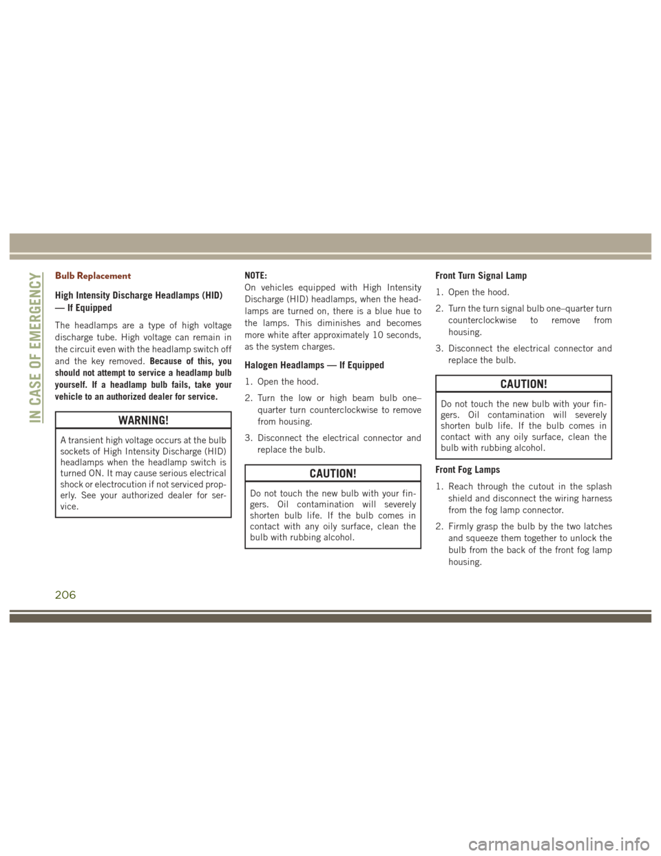
Bulb Replacement
High Intensity Discharge Headlamps (HID)
—
If Equipped
The headlamps are a type of high voltage
discharge tube. High voltage can remain in
the circuit even with the headlamp switch off
and the key removed. Because of this, you
should not attempt to service a headlamp bulb
yourself. If a headlamp bulb fails, take your
vehicle to an authorized dealer for service.
WARNING!
A transient high voltage occurs at the bulb
sockets of High Intensity Discharge (HID)
headlamps when the headlamp switch is
turned ON. It may cause serious electrical
shock or electrocution if not serviced prop-
erly. See your authorized dealer for ser-
vice. NOTE:
On vehicles equipped with High Intensity
Discharge (HID) headlamps, when the head-
lamps are turned on, there is a blue hue to
the lamps. This diminishes and becomes
more white after approximately 10 seconds,
as the system charges.
Halogen Headlamps — If Equipped
1. Open the hood.
2. Turn the low or high beam bulb one–
quarter turn counterclockwise to remove
from housing.
3. Disconnect the electrical connector and replace the bulb.
CAUTION!
Do not touch the new bulb with your fin-
gers. Oil contamination will severely
shorten bulb life. If the bulb comes in
contact with any oily surface, clean the
bulb with rubbing alcohol.
Front Turn Signal Lamp
1. Open the hood.
2. Turn the turn signal bulb one–quarter turncounterclockwise to remove from
housing.
3. Disconnect the electrical connector and replace the bulb.
CAUTION!
Do not touch the new bulb with your fin-
gers. Oil contamination will severely
shorten bulb life. If the bulb comes in
contact with any oily surface, clean the
bulb with rubbing alcohol.
Front Fog Lamps
1. Reach through the cutout in the splashshield and disconnect the wiring harness
from the fog lamp connector.
2. Firmly grasp the bulb by the two latches and squeeze them together to unlock the
bulb from the back of the front fog lamp
housing.
IN CASE OF EMERGENCY
206
Page 209 of 372
3. Pull the bulb straight out from the keyedopening in the housing.
CAUTION!
•Do not touch the new bulb with your
fingers. Oil contamination will severely
shorten bulb life. If the bulb comes in
contact with any oily surface, clean the
bulb with rubbing alcohol.
• Always use the correct bulb size and type for replacement. An incorrect bulb size
or type may overheat and cause damage
to the lamp, the socket or the lamp
wiring.
4. Align the index tabs of the front fog lamp bulb with the slots in the collar of the bulb
opening on the back of the front fog lamp
housing.
5. Insert the bulb into the housing until the index tabs are engaged in the slots of the
collar.
6. Firmly and evenly push the bulb straight into the lamp housing until both tabs snap
firmly into place and are fully engaged. 7. Connect the wiring harness to the front fog
lamp connector.
Rear Tail, Stop, and Turn Signal Lamps
1. Raise the liftgate.
2. Remove the two push-pins from the taillamp housing.
3. Grasp the tail lamp and pull firmly rear- ward to disengage the lamp from the ap-
erture panel. 4. Twist socket counter clockwise and re-
move from lamp.
5. Pull the bulb to remove it from the socket.
6. Replace the bulb, reinstall the socket, and reattach the lamp assembly.
Tail Lamp Push Pins
Rear Of Tail Lamp
1 — Rear Stop Lamp Bulb Socket
2 — LED Tail Connector – Do Not Re-
move
3 — Rear Turn Signal Bulb Socket
207
Page 300 of 372
Maintaining Your Uconnect Access
Account
Selling Your Vehicle
When you sell your vehicle, we recommend
that you remove your Uconnect Access Ac-
count information from the vehicle. You can
do this on the Mopar Owner Connect website
moparownerconnect.com. Removing your ac-
count information cancels your subscription
and makes your vehicle factory-ready for a
new owner/subscriber.
For additional information on Uconnect, visit
DriveUconnect.com or call 1-877-855-8400
Built-In Features
WARNING!
ALWAYS drive safely with your hands on
the wheel. You have full responsibility and
assume all risks related to the use of the
Uconnect features and applications in this
vehicle. Only use Uconnect when it is safe
to do so. Failure to do so may result in an
accident involving serious injury or death.
WARNING!
• ALWAYS obey traffic laws and pay atten-tion to the road. Some Uconnect Access
services, including 9-1-1 and Assist,
will NOT work without an operable 1X
(voice/data) or 3G (data) network con-
nection.
• Ignoring the rearview mirror light could
mean you may not have 9-1-1 Call ser-
vice if needed. If the rearview mirror
light is illuminated, have an authorized
dealer service the 9-1-1 Call system
immediately.
• The Occupant Restraint Controller
(ORC) turns on the Air Bag Warning
Light on the instrument panel if a mal-
function is detected in any part of the
airbag system. If the Air Bag Warning
Light is illuminated, the air bag system
may not be working properly and the
9-1-1 system may not send a signal to a
9-1-1 operator if an air bag is deployed.
If the Air Bag Warning Light is illumi-
nated, have an authorized dealer service
your vehicle immediately.
WARNING!
• If anyone in the vehicle could be indanger (e.g., fire or smoke is visible,
dangerous road conditions or location),
do not wait for voice contact from a
9-1-1 operator. All occupants should
exit the vehicle immediately and move
to a safe location.
• The 9-1-1 Call system is embedded into
the vehicle’s electrical system. Do not
add aftermarket electrical equipment to
the vehicle’s electrical system. This may
prevent your vehicle from sending a sig-
nal to initiate an emergency call. To
avoid interference that can cause the
9-1-1 Call system to fail, never add
aftermarket equipment (e.g., two-way
mobile radio, CB radio, data recorder,
etc.) to your vehicle’s electrical system
or modify the antennas on your vehicle.
• IF YOUR VEHICLE LOSES BATTERY
POWER FOR ANY REASON (INCLUD-
ING DURING OR AFTER AN ACCI-
DENT), the Uconnect features, apps and
services, among others, will not operate.
MULTIMEDIA
298