JEEP GRAND CHEROKEE 2017 WK2 / 4.G User Guide
Manufacturer: JEEP, Model Year: 2017, Model line: GRAND CHEROKEE, Model: JEEP GRAND CHEROKEE 2017 WK2 / 4.GPages: 372
Page 201 of 372
Recreational Towing-Two Wheel Drive
Models
DO NOT flat tow this vehicle. Damage to the
drivetrain will result.
Recreational towing (for two-wheel drive
models) is allowed ONLY if the rear wheels
are OFF the ground. This may be accom-
plished using a tow dolly or vehicle trailer. If
using a tow dolly, follow this procedure:
1. Properly secure the dolly to the tow ve-hicle, following the dolly manufacturer's
instructions.
NOTE:
If vehicle is equipped with Quadra-Lift air
suspension, ensure the vehicle is set to
Normal Ride Height.
2. Drive the rear wheels onto the tow dolly.
3. Firmly apply the parking brake. Shift the transmission into PARK.
4. Turn the ignition OFF.
5. Properly secure the rear wheels to the dolly, following the dolly manufacturer’s
instructions. 6. Install a suitable clamping device, de-
signed for towing, to secure the front
wheels in the straight position.
CAUTION!
Towing with the rear wheels on the ground
will cause severe transmission damage.
Damage from improper towing is not cov-
ered under the New Vehicle Limited War-
ranty.
Recreational Towing — Quadra-Trac I
(Single-Speed Transfer Case) Four-Wheel
Drive Models
Recreational towing is not allowed. These
models do not have a NEUTRAL (N) position
in the transfer case.
NOTE:
This vehicle may be towed on a flatbed or
vehicle trailer provided all four wheels are OFF
the ground.
CAUTION!
Towing this vehicle in violation of the
above requirements can cause severe
transmission and/or transfer case damage.
Damage from improper towing is not cov-
ered under the New Vehicle Limited War-
ranty.
Recreational Towing — Quadra–Trac
II/Quadra–Drive II Four-Wheel Drive
Models
The transfer case must be shifted into NEU-
TRAL (N) and the transmission must be in
PARK for recreational towing. The NEUTRAL
(N) selection button is adjacent to the trans-
fer case selector switch. Shifts into and out of
transfer case NEUTRAL (N) can take place
with the selector switch in any mode position.
CAUTION!
• DO NOT dolly tow any 4WD vehicle. Towing with only one set of wheels on the
ground (front or rear) will cause severe
transmission and/or transfer case dam-
199
Page 202 of 372
CAUTION!
age. Tow with all four wheels either ON
the ground, or OFF the ground (using a
vehicle trailer).
• Tow only in a forward direction. Towing
this vehicle backwards can cause severe
damage to the transfer case.
• The transmission must be in PARK for
recreational towing.
• Before recreational towing, perform the
procedure outlined under “Shifting into
NEUTRAL (N)” to be certain that the
transfer case is fully in NEUTRAL (N).
Otherwise, internal damage will result.
• Towing this vehicle in violation of the
above requirements can cause severe
transmission and/or transfer case dam-
age. Damage from improper towing is
not covered under the New Vehicle Lim-
ited Warranty.
• Do not use a bumper-mounted clamp-on
tow bar on your vehicle. The bumper
face bar will be damaged.
Shifting Into NEUTRAL (N)
WARNING!
You or others could be injured or killed if
you leave the vehicle unattended with the
transfer case in the NEUTRAL (N) position
without first fully engaging the parking
brake. The transfer case NEUTRAL (N)
position disengages both the front and rear
driveshafts from the powertrain and will
allow the vehicle to roll, even if the trans-
mission is in PARK. The parking brake
should always be applied when the driver
is not in the vehicle.
Use the following procedure to prepare your
vehicle for recreational towing.
CAUTION!
It is necessary to follow these steps to be
certain that the transfer case is fully in
NEUTRAL (N) before recreational towing
to prevent damage to internal parts. 1. Bring the vehicle to a complete stop, with
the engine running.
2. Press and hold the brake pedal.
3. Shift the transmission into NEUTRAL.
4. If vehicle is equipped with Quadra-Lift air suspension, ensure the vehicle is set to
Normal Ride Height.
5. Using a ballpoint pen or similar object, push and hold the recessed transfer case
NEUTRAL (N) button (located by the se-
lector switch) for four seconds. The light
behind the N symbol will blink, indicating
shift in progress. The light will stop blink-
ing (stay on solid) when the shift to NEU-
TRAL (N) is complete. A “FOUR WHEEL
DRIVE SYSTEM IN NEUTRAL” message
will appear in the instrument cluster.
STARTING AND OPERATING
200
Page 203 of 372
6. After the shift is completed and the NEU-TRAL (N) light stays on, release the NEU-
TRAL (N) button.
7. Shift the transmission into REVERSE.
8. Release the brake pedal for five seconds and ensure that there is no vehicle
movement.
9. Press and hold the brake pedal. Shift the transmission back into NEUTRAL.
10. Firmly apply the parking brake. 11. With the transmission and transfer case
in NEUTRAL, push and hold the EN-
GINE START/STOP button until the en-
gine turns off.
12. Place the transmission gear selector in PARK. Release the brake pedal.
13. Push the ENGINE STOP/START button twice (without pressing the brake pedal),
to turn the ignition to the OFF mode.
14. Attach the vehicle to the tow vehicle using a suitable tow bar.
15. Release the parking brake.
NOTE:
• Steps 1 through 4 are requirements that must be met before pushing the NEUTRAL
(N) button, and must continue to be met
until the shift has been completed. If any
of these requirements are not met before
pushing the NEUTRAL (N) button or are
no longer met during the shift, then the
NEUTRAL (N) indicator light will flash
continuously until all requirements are
met or until the NEUTRAL (N) button is
released. • The ignition must be in the ON/RUN mode
for a shift to take place and for the position
indicator lights to be operable. If the igni-
tion is not in the ON/RUN mode, the shift
will not take place and no position indica-
tor lights will be on or flashing.
• A flashing NEUTRAL (N) position indica- tor light indicates that shift requirements
have not been met.
• If the vehicle is equipped with Quadra-Lift air suspension, the engine should be
started and left running for a minimum of
60 seconds (with all the doors closed) at
least once every 24 hours. This process
allows the air suspension to adjust the
vehicle’s ride height to compensate for
temperature effects.
Shifting Out Of NEUTRAL (N)
Use the following procedure to prepare your
vehicle for normal usage.
1. Bring the vehicle to a complete stop, leav-
ing it connected to the tow vehicle.
2. Firmly apply the parking brake.
3. Start the engine.
4. Press and hold the brake pedal.
NEUTRAL (N) Switch
201
Page 204 of 372
5. Shift the transmission into NEUTRAL.
6. Using a ballpoint pen or similar object,push and hold the recessed transfer case
NEUTRAL (N) button (located by the se-
lector switch) for one second.
7. When the NEUTRAL (N) indicator light turns off, release the NEUTRAL (N) but-
ton. After the NEUTRAL (N) button has
been released, the transfer case will shift
to the position indicated by the selector
switch. 8. Shift the transmission into PARK. Turn
the engine OFF.
9. Release the brake pedal.
10. Disconnect vehicle from the tow vehicle.
11. Start the engine.
12. Press and hold the brake pedal.
13. Release the parking brake.
14. Shift the transmission into DRIVE, re- lease the brake pedal, and check that
the vehicle operates normally.
NOTE:
• Steps 1 through 5 are requirements that must be met before pushing the NEU-
TRAL (N) button, and must continue to be
met until the shift has been completed. If
any of these requirements are not met
before pushing the NEUTRAL (N) button
or are no longer met during the shift, the
NEUTRAL (N) indicator light will flash
continuously until all requirements are
met or until the NEUTRAL (N) button is
released. • The ignition must be in the ON/RUN mode
for a shift to take place and for the position
indicator lights to be operable. If the igni-
tion is not in the ON/RUN mode, the shift
will not take place and no position indica-
tor lights will be on or flashing.
• A flashing NEUTRAL (N) position indica- tor light indicates that shift requirements
have not been met.
NEUTRAL (N) Switch
STARTING AND OPERATING
202
Page 205 of 372
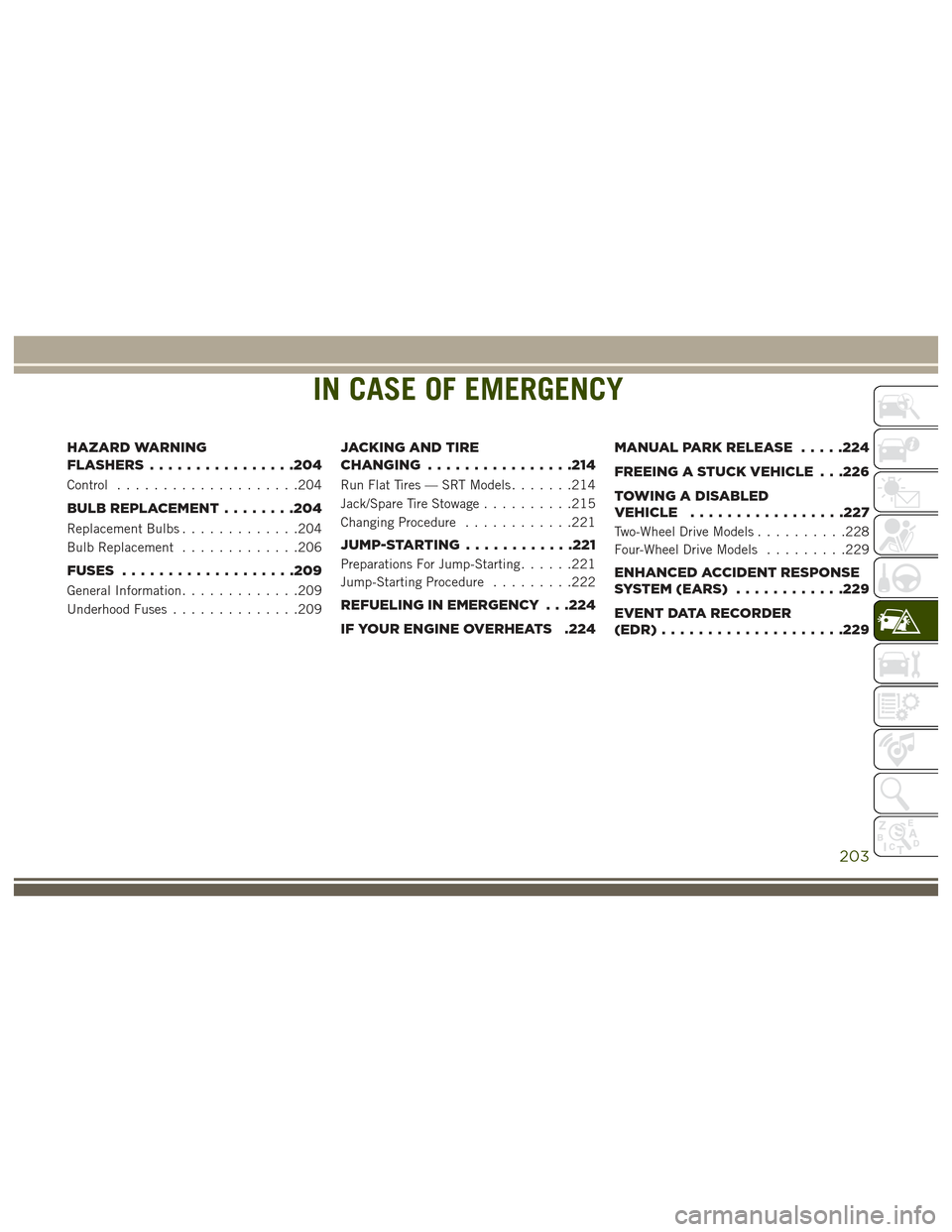
IN CASE OF EMERGENCY
HAZARD WARNING
FLASHERS................204
Control....................204
BULB REPLACEMENT ........204
Replacement Bulbs.............204
Bulb Replacement .............206
FUSES ...................209
General Information.............209
Underhood Fuses ..............209
JACKING AND TIRE
CHANGING............... .214
Run Flat Tires — SRT Models .......214
Jack/Spare Tire Stowage ..........215
Changing Procedure ............221
JUMP-STARTING............221
Preparations For Jump-Starting ......221
Jump-Starting Procedure .........222
REFUELING IN EMERGENCY . . .224
IF YOUR ENGINE OVERHEATS .224 MANUAL PARK RELEASE
.....224
FREEING A STUCK VEHICLE . . .226
TOWING A DISABLED
VEHICLE ................ .227
Two-Wheel Drive Models..........228
Four-Wheel Drive Models .........229
ENHANCED ACCIDENT RESPONSE
SYSTEM(EARS) ........... .229
EVENT DATA RECORDER
(EDR)................... .229
IN CASE OF EMERGENCY
203
Page 206 of 372
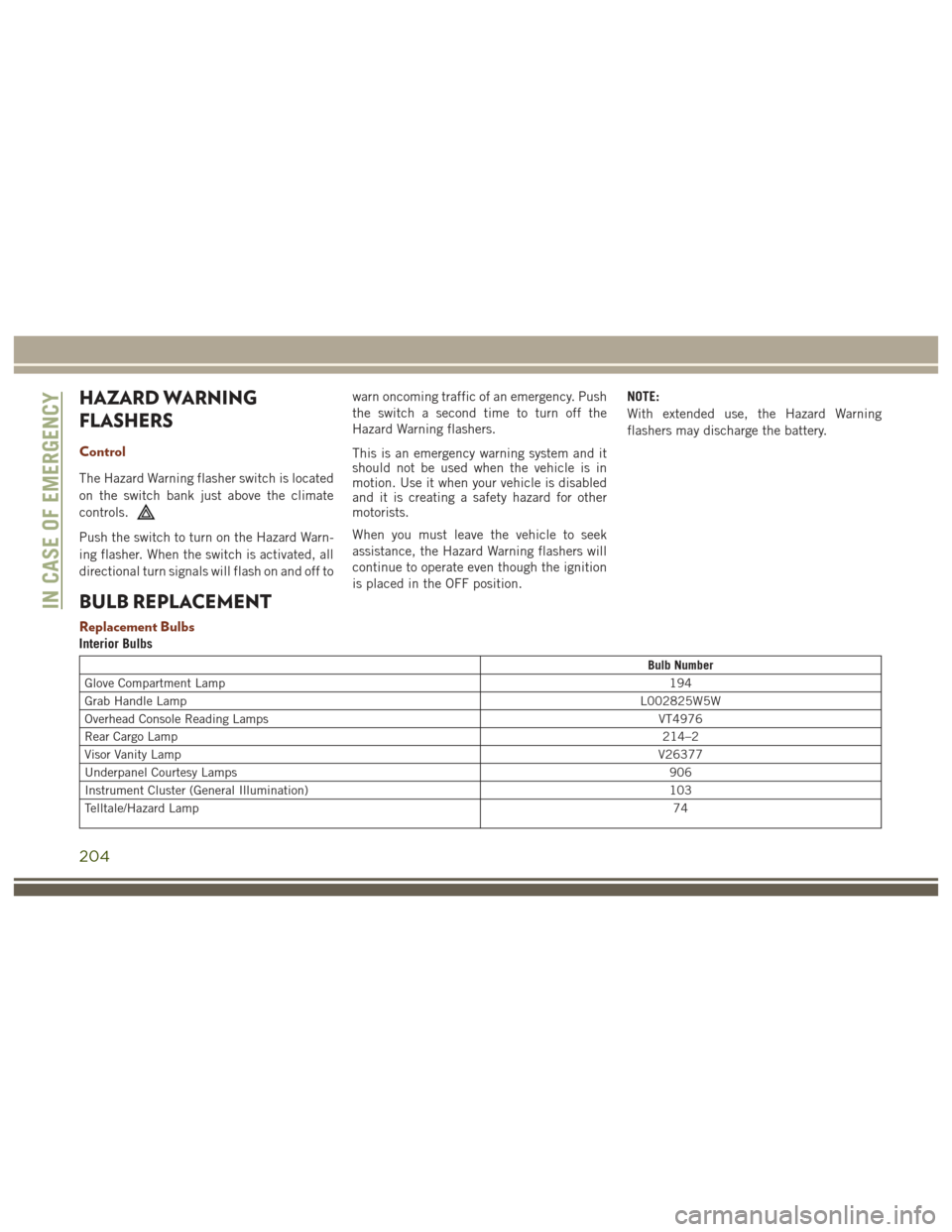
HAZARD WARNING
FLASHERS
Control
The Hazard Warning flasher switch is located
on the switch bank just above the climate
controls.
Push the switch to turn on the Hazard Warn-
ing flasher. When the switch is activated, all
directional turn signals will flash on and off towarn oncoming traffic of an emergency. Push
the switch a second time to turn off the
Hazard Warning flashers.
This is an emergency warning system and it
should not be used when the vehicle is in
motion. Use it when your vehicle is disabled
and it is creating a safety hazard for other
motorists.
When you must leave the vehicle to seek
assistance, the Hazard Warning flashers will
continue to operate even though the ignition
is placed in the OFF position. NOTE:
With extended use, the Hazard Warning
flashers may discharge the battery.
BULB REPLACEMENT
Replacement Bulbs
Interior Bulbs
Bulb Number
Glove Compartment Lamp 194
Grab Handle Lamp L002825W5W
Overhead Console Reading Lamps VT4976
Rear Cargo Lamp 214–2
Visor Vanity Lamp V26377
Underpanel Courtesy Lamps 906
Instrument Cluster (General Illumination) 103
Telltale/Hazard Lamp 74
IN CASE OF EMERGENCY
204
Page 207 of 372
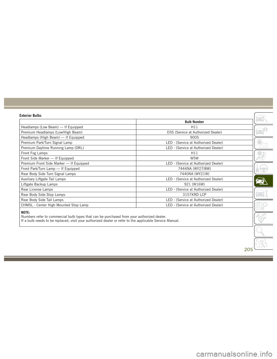
Exterior Bulbs
Bulb Number
Headlamps (Low Beam) — If Equipped H11
Premium Headlamps (Low/High Beam) D3S (Service at Authorized Dealer)
Headlamps (High Beam) — If Equipped 9005
Premium Park/Turn Signal Lamp LED - (Service at Authorized Dealer)
Premium Daytime Running Lamp (DRL) LED - (Service at Authorized Dealer)
Front Fog Lamps H11
Front Side Marker — If Equipped W5W
Premium Front Side Marker — If Equipped LED - (Service at Authorized Dealer)
Front Park/Turn Lamp — If Equipped 7444NA (WY27/8W)
Rear Body Side Turn Signal Lamps 7440NA (WY21W)
Auxiliary Liftgate Tail Lamps LED - (Service at Authorized Dealer)
Liftgate Backup Lamps 921 (W16W)
Rear License Lamps LED - (Service at Authorized Dealer)
Rear Body Side Stop Lamps 3157KRD LCP
Rear Body Side Tail Lamps LED - (Service at Authorized Dealer)
CHMSL - Center High Mounted Stop Lamp LED - (Service at Authorized Dealer)
NOTE:
Numbers refer to commercial bulb types that can be purchased from your authorized dealer.
If a bulb needs to be replaced, visit your authorized dealer or refer to the applicable Service Manual.
205
Page 208 of 372
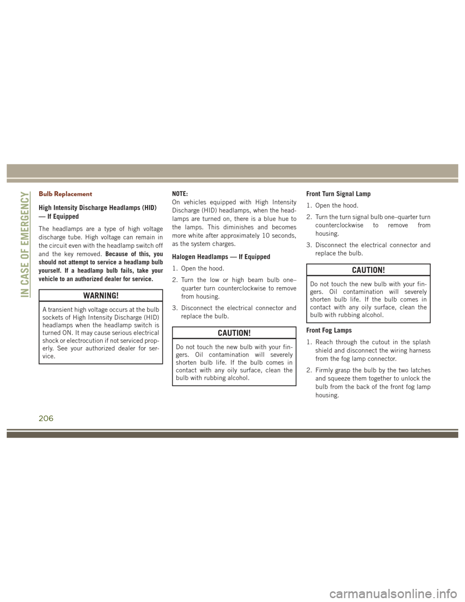
Bulb Replacement
High Intensity Discharge Headlamps (HID)
—
If Equipped
The headlamps are a type of high voltage
discharge tube. High voltage can remain in
the circuit even with the headlamp switch off
and the key removed. Because of this, you
should not attempt to service a headlamp bulb
yourself. If a headlamp bulb fails, take your
vehicle to an authorized dealer for service.
WARNING!
A transient high voltage occurs at the bulb
sockets of High Intensity Discharge (HID)
headlamps when the headlamp switch is
turned ON. It may cause serious electrical
shock or electrocution if not serviced prop-
erly. See your authorized dealer for ser-
vice. NOTE:
On vehicles equipped with High Intensity
Discharge (HID) headlamps, when the head-
lamps are turned on, there is a blue hue to
the lamps. This diminishes and becomes
more white after approximately 10 seconds,
as the system charges.
Halogen Headlamps — If Equipped
1. Open the hood.
2. Turn the low or high beam bulb one–
quarter turn counterclockwise to remove
from housing.
3. Disconnect the electrical connector and replace the bulb.
CAUTION!
Do not touch the new bulb with your fin-
gers. Oil contamination will severely
shorten bulb life. If the bulb comes in
contact with any oily surface, clean the
bulb with rubbing alcohol.
Front Turn Signal Lamp
1. Open the hood.
2. Turn the turn signal bulb one–quarter turncounterclockwise to remove from
housing.
3. Disconnect the electrical connector and replace the bulb.
CAUTION!
Do not touch the new bulb with your fin-
gers. Oil contamination will severely
shorten bulb life. If the bulb comes in
contact with any oily surface, clean the
bulb with rubbing alcohol.
Front Fog Lamps
1. Reach through the cutout in the splashshield and disconnect the wiring harness
from the fog lamp connector.
2. Firmly grasp the bulb by the two latches and squeeze them together to unlock the
bulb from the back of the front fog lamp
housing.
IN CASE OF EMERGENCY
206
Page 209 of 372
3. Pull the bulb straight out from the keyedopening in the housing.
CAUTION!
•Do not touch the new bulb with your
fingers. Oil contamination will severely
shorten bulb life. If the bulb comes in
contact with any oily surface, clean the
bulb with rubbing alcohol.
• Always use the correct bulb size and type for replacement. An incorrect bulb size
or type may overheat and cause damage
to the lamp, the socket or the lamp
wiring.
4. Align the index tabs of the front fog lamp bulb with the slots in the collar of the bulb
opening on the back of the front fog lamp
housing.
5. Insert the bulb into the housing until the index tabs are engaged in the slots of the
collar.
6. Firmly and evenly push the bulb straight into the lamp housing until both tabs snap
firmly into place and are fully engaged. 7. Connect the wiring harness to the front fog
lamp connector.
Rear Tail, Stop, and Turn Signal Lamps
1. Raise the liftgate.
2. Remove the two push-pins from the taillamp housing.
3. Grasp the tail lamp and pull firmly rear- ward to disengage the lamp from the ap-
erture panel. 4. Twist socket counter clockwise and re-
move from lamp.
5. Pull the bulb to remove it from the socket.
6. Replace the bulb, reinstall the socket, and reattach the lamp assembly.
Tail Lamp Push Pins
Rear Of Tail Lamp
1 — Rear Stop Lamp Bulb Socket
2 — LED Tail Connector – Do Not Re-
move
3 — Rear Turn Signal Bulb Socket
207
Page 210 of 372
Rear Liftgate Mounted Tail Lamp
1. Raise the liftgate.
2. Use a suitable tool to pry the lower trimfrom the liftgate. 3. Continue removing the trim.
4. Disconnect the two trim panel lights.
5. Tail lamps are now visible. Rotate sock-
et(s) counter clockwise.
6. Remove/replace bulb(s).
7. Reinstall the socket(s).
8. Reverse process to reinstall the liftgatetrim.
Rear Liftgate Tail Lamps
Liftgate Lower Trim
Rear Of Liftgate Tail Lamp
1 — Auxiliary LED Tail Connector – Do
Not Remove
2 — Backup Bulb Socket
IN CASE OF EMERGENCY
208