center console JEEP GRAND CHEROKEE 2017 WK2 / 4.G User Guide
[x] Cancel search | Manufacturer: JEEP, Model Year: 2017, Model line: GRAND CHEROKEE, Model: JEEP GRAND CHEROKEE 2017 WK2 / 4.GPages: 372
Page 30 of 372
You can choose from HI, LO or OFF heat
settings. The indicator arrows in touchscreen
buttons indicate the level of heat in use. Two
indicator arrows will illuminate for HI, one for
LO and none for OFF.
• Press the heated seat button
once to
turn the HI setting ON.
• Press the heated seat button
a second
time to turn the LO setting ON.
• Press the heated seat button
a third
time to turn the heating elements OFF.
If the HI-level setting is selected, the system
will automatically switch to LO-level after
approximately 60 minutes of continuous op-
eration. At that time, the display will change
from HI to LO, indicating the change. The
LO-level setting will turn OFF automatically
after approximately 45 minutes.
NOTE:
• Once a heat setting is selected, heat will be felt within two to five minutes.
• The engine must be running for the heated seats to operate. Vehicles Equipped With Remote Start
On models that are equipped with remote
start, the heated seats can be programmed to
come on during a remote start.
This feature can be programmed through the
Uconnect system. Refer to your Owner's
Manual
at
www.jeep.com/en/owners/manuals/ for fur-
ther details.
WARNING!
• Persons who are unable to feel pain to the skin because of advanced age,
chronic illness, diabetes, spinal cord in-
jury, medication, alcohol use, exhaus-
tion or other physical condition must
exercise care when using the seat
heater. It may cause burns even at low
temperatures, especially if used for long
periods of time.
• Do not place anything on the seat or
seatback that insulates against heat,
such as a blanket or cushion. This may
cause the seat heater to overheat. Sit-
ting in a seat that has been overheated
WARNING!
could cause serious burns due to the
increased surface temperature of the
seat.
Rear Heated Seats
On some models, the two outboard seats are
equipped with heated seats. The heated seat
switches for these seats are located on the
rear of the center console. There are two
heated seat switches
that allow the rear
passengers to operate the seats indepen-
dently.
You can choose from HI, LO or OFF heat
settings. The indicator lights in each switch
indicate the level of heat in use. Two indica-
tor lights will illuminate for HI, one for LO
and none for OFF.
• Push the heated seat button
once to
select HI-level heating.
• Push the heated seat button
a second
time to select LO-level heating.
• Push the heated seat button
a third
time to turn the heating elements OFF.
GETTING TO KNOW YOUR VEHICLE
28
Page 60 of 372
WARNING!
Be sure the hood is fully latched before
driving your vehicle. If the hood is not fully
latched, it could open when the vehicle is
in motion and block your vision. Failure to
follow this warning could result in serious
injury or death.
Closing
1. Before closing the hood, check to makesure all filler caps are correctly installed.
2. Lower the hood halfway and push down to close the hood and securely latch it into
place.
WARNING!
Be sure the hood is fully latched before
driving your vehicle. If the hood is not fully
latched, it could open when the vehicle is
in motion and block your vision. Failure to
follow this warning could result in serious
injury or death.
CAUTION!
To prevent possible damage, do not slam
the hood to close it. Use a firm downward
push at the front center of the hood to
ensure that both latches engage.
LIFTGATE
Opening
The liftgate can be opened from inside the
vehicle using the Power Liftgate button on
the overhead console, using the key fob out-
side of the vehicle or the Electronic Liftgate
Release.
To Unlock/Enter The Liftgate
The liftgate may be released in several ways:
• Key fob
• Outside handle
• Button on Overhead Console The liftgate passive entry unlock feature is
built into the electronic liftgate release. With
a valid Passive Entry Key Fob within 5 ft
(1.5 m) of the liftgate, push the electronic
liftgate release to open with one fluid motion.
Push the button on the key fob twice within
five seconds to release the liftgate.
NOTE:
If “Unlock All Doors 1st Press” is pro-
grammed in the instrument cluster display,
all doors will unlock when you push the
electronic release on the liftgate. If "Unlock
Driver Door 1st Press" is programmed in
Uconnect, the liftgate will unlock when you
push the electronic release on the liftgate.
Refer to “Uconnect Settings” in “Multime-
dia” for further information.
GETTING TO KNOW YOUR VEHICLE
58
Page 64 of 372
WARNING!
jured. Use only the anchors provided for
child seat tethers.
The weight and position of cargo and pas-
sengers can change the vehicle center of
gravity and vehicle handling. To avoid loss
of control resulting in personal injury, fol-
low these guidelines for loading your ve-
hicle:
• Do not carry loads which exceed the load
limits described on the label attached to
the left door or left door center pillar.
• Always place cargo evenly on the cargo
floor. Put heavier objects as low and as
far forward as possible.
• Place as much cargo as possible in front
of the rear axle. Too much weight or
improperly placed weight over or behind
the rear axle can cause the rear of the
vehicle to sway.
• Do not pile luggage or cargo higher than
the top of the seatback. This could im-
pair visibility or become a dangerous
projectile in a sudden stop or accident.
UNIVERSAL GARAGE DOOR
OPENER (HomeLink)
• HomeLink replaces up to three hand-held
transmitters that operate devices such as
garage door openers, motorized gates,
lighting or home security systems. The
HomeLink unit is powered by your vehicles
12 Volt battery. • The HomeLink buttons that are located in
the overhead console or sunvisor desig-
nate the three different HomeLink chan-
nels.
• The HomeLink indicator is located above the center button.
Before You Begin Programming
HomeLink
Ensure that your vehicle is parked outside of
the garage before you begin programming.
For efficient programming and accurate
transmission of the radio-frequency signal, it
is recommended that a new battery be placed
in the hand-held transmitter of the device
that is being programmed to the HomeLink
system.
To erase the channels, place the ignition
switch into the ON/RUN position, then push
and hold the two outside HomeLink buttons
(I and III) for up to 20 seconds or until the red
indicator flashes.
Universal Garage Door Opener (HomeLink)GETTING TO KNOW YOUR VEHICLE
62
Page 67 of 372
A second front power outlet is located inside
the center console.
The rear power outlet is located in the right
rear cargo area.The power outlets are labeled with either a
“key” or a “battery” symbol to indicate how
the outlet is powered. Power outlets labeled
with a “key” are powered when the ignition
switch is in the ON/RUN or ACC position,
while the outlets labeled with a “battery” are
connected directly to the battery and pow-
ered at all times.
NOTE:
• Do not exceed the maximum power of
160 Watts (13 Amps) at 12 Volts. If the
160 Watt (13 Amp) power rating is ex-
ceeded, the fuse protecting the system
will need to be replaced.
• Power outlets are designed for accessory plugs only. Do not insert any other object
in the power outlet as this will damage the
outlet and blow the fuse. Improper use of
the power outlet can cause damage not
covered by your new vehicle warranty. • The rear cargo power outlet can be
switched to “battery” powered all the time
by switching the power outlet right rear
quarter panel fuse in the fuse panel.
Center Console Power Outlet
65
Page 68 of 372
Power Outlet Fuse Locations
1 — F90 – F91 Fuse 20A Yellow Power Outlet Right Rear Quarter Panel
2 — F104 Fuse 20A Yellow Power Outlet Center Console
3 — F93 Fuse 20A Yellow Cigar Lighter Instrument PanelGETTING TO KNOW YOUR VEHICLE
66
Page 69 of 372
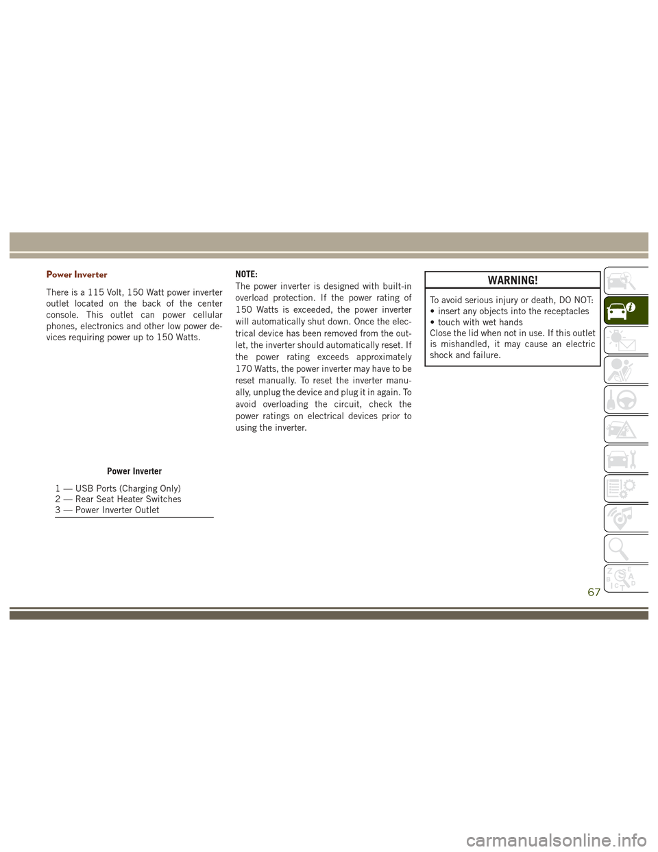
Power Inverter
There is a 115 Volt, 150 Watt power inverter
outlet located on the back of the center
console. This outlet can power cellular
phones, electronics and other low power de-
vices requiring power up to 150 Watts.NOTE:
The power inverter is designed with built-in
overload protection. If the power rating of
150 Watts is exceeded, the power inverter
will automatically shut down. Once the elec-
trical device has been removed from the out-
let, the inverter should automatically reset. If
the power rating exceeds approximately
170 Watts, the power inverter may have to be
reset manually. To reset the inverter manu-
ally, unplug the device and plug it in again. To
avoid overloading the circuit, check the
power ratings on electrical devices prior to
using the inverter.
WARNING!
To avoid serious injury or death, DO NOT:
• insert any objects into the receptacles
• touch with wet hands
Close the lid when not in use. If this outlet
is mishandled, it may cause an electric
shock and failure.
Power Inverter
1 — USB Ports (Charging Only)
2 — Rear Seat Heater Switches
3 — Power Inverter Outlet
67
Page 161 of 372
• In SRT models, the transmission willlaunch (from a stop) in second gear, and
the torque converter clutch may engage at
lower engine speeds and remain on longer.
• Some ECO mode functions may be tempo- rarily inhibited based on temperature and
other factors.
Active Noise Cancellation — Summit And
SRT Models Only
Your vehicle is equipped with an Active Noise
Cancellation System. This system uses four
microphones embedded in the headliner to
detect undesirable exhaust noise, which
sometimes occurs when operating in ECO
mode. An onboard frequency generator cre-
ates counteracting sound waves through the
audio system to help keep the vehicle quiet.
Eight–Speed Automatic Transmission
Your vehicle is equipped with a fuel efficient
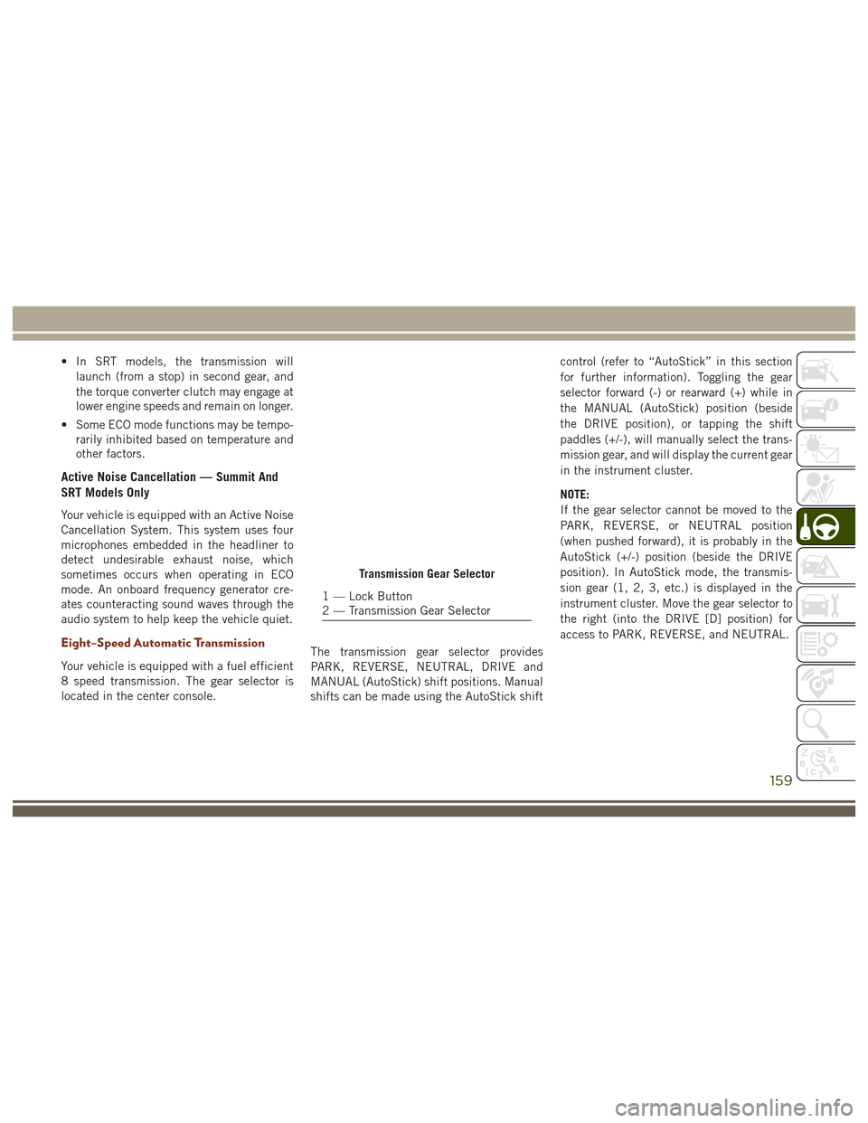
8 speed transmission. The gear selector is
located in the center console. The transmission gear selector provides
PARK, REVERSE, NEUTRAL, DRIVE and
MANUAL (AutoStick) shift positions. Manual
shifts can be made using the AutoStick shiftcontrol (refer to “AutoStick” in this section
for further information). Toggling the gear
selector forward (-) or rearward (+) while in
the MANUAL (AutoStick) position (beside
the DRIVE position), or tapping the shift
paddles (+/-), will manually select the trans-
mission gear, and will display the current gear
in the instrument cluster.
NOTE:
If the gear selector cannot be moved to the
PARK, REVERSE, or NEUTRAL position
(when pushed forward), it is probably in the
AutoStick (+/-) position (beside the DRIVE
position). In AutoStick mode, the transmis-
sion gear (1, 2, 3, etc.) is displayed in the
instrument cluster. Move the gear selector to
the right (into the DRIVE [D] position) for
access to PARK, REVERSE, and NEUTRAL.
Transmission Gear Selector
1 — Lock Button
2 — Transmission Gear Selector
159
Page 168 of 372
QUADRA-LIFT — IF
EQUIPPED
Description
The Quadra-Lift air suspension system pro-
vides full time load leveling capability along
with the benefit of vehicle height adjustment
by the push of a button. The vehicle will
automatically raise and lower the ride height
to adapt to the appropriate driving condi-
tions. At higher speeds, the vehicle will lower
to an aerodynamic ride height and when
operating in off-road modes, the vehicle will
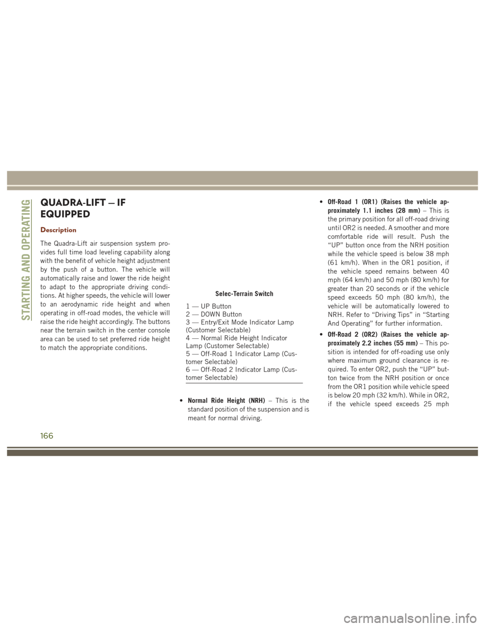
raise the ride height accordingly. The buttons
near the terrain switch in the center console
area can be used to set preferred ride height
to match the appropriate conditions.•Normal Ride Height (NRH) – This is the
standard position of the suspension and is
meant for normal driving. •
Off-Road 1 (OR1) (Raises the vehicle ap-
proximately 1.1 inches (28 mm) – This is
the primary position for all off-road driving
until OR2 is needed. A smoother and more
comfortable ride will result. Push the
“UP” button once from the NRH position
while the vehicle speed is below 38 mph
(61 km/h). When in the OR1 position, if
the vehicle speed remains between 40
mph (64 km/h) and 50 mph (80 km/h) for
greater than 20 seconds or if the vehicle
speed exceeds 50 mph (80 km/h), the
vehicle will be automatically lowered to
NRH. Refer to “Driving Tips” in “Starting
And Operating” for further information.
• Off-Road 2 (OR2) (Raises the vehicle ap-
proximately 2.2 inches (55 mm) – This po-
sition is intended for off-roading use only
where maximum ground clearance is re-
quired. To enter OR2, push the “UP” but-
ton twice from the NRH position or once
from the OR1 position while vehicle speed
is below 20 mph (32 km/h). While in OR2,
if the vehicle speed exceeds 25 mph
Selec-Terrain Switch
1 — UP Button
2 — DOWN Button
3 — Entry/Exit Mode Indicator Lamp
(Customer Selectable)
4 — Normal Ride Height Indicator
Lamp (Customer Selectable)
5 — Off-Road 1 Indicator Lamp (Cus-
tomer Selectable)
6 — Off-Road 2 Indicator Lamp (Cus-
tomer Selectable)
STARTING AND OPERATING
166
Page 216 of 372
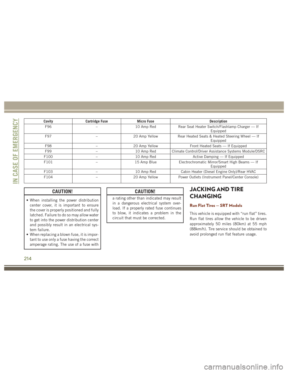
CavityCartridge Fuse Micro Fuse Description
F96 –10 Amp Red Rear Seat Heater Switch/Flashlamp Charger — If
Equipped
F97 –20 Amp Yellow Rear Heated Seats & Heated Steering Wheel — If
Equipped
F98 –20 Amp Yellow Front Heated Seats — If Equipped
F99 –10 Amp Red Climate Control/Driver Assistance Systems Module/DSRC
F100 –10 Amp Red Active Damping — If Equipped
F101 –15 Amp Blue Electrochromatic Mirror/Smart High Beams — If
Equipped
F103 –10 Amp Red Cabin Heater (Diesel Engine Only)/Rear HVAC
F104 –20 Amp Yellow Power Outlets (Instrument Panel/Center Console)
CAUTION!
• When installing the power distribution
center cover, it is important to ensure
the cover is properly positioned and fully
latched. Failure to do so may allow water
to get into the power distribution center
and possibly result in an electrical sys-
tem failure.
• When replacing a blown fuse, it is impor-
tant to use only a fuse having the correct
amperage rating. The use of a fuse with
CAUTION!
a rating other than indicated may result
in a dangerous electrical system over-
load. If a properly rated fuse continues
to blow, it indicates a problem in the
circuit that must be corrected.
JACKING AND TIRE
CHANGING
Run Flat Tires — SRT Models
This vehicle is equipped with “run flat” tires.
Run flat tires allow the vehicle to be driven
approximately 50 miles (80km) at 55 mph
(88km/h). Tire service should be obtained to
avoid prolonged run flat feature usage.
IN CASE OF EMERGENCY
214
Page 227 of 372
In order to move the vehicle in cases where
the transmission will not shift out of PARK
(such as a discharged battery), a Manual Park
Release is available.
Follow these steps to use the Manual Park
Release:
1. Firmly apply the parking brake.
2. Open the center console and locate theManual Park Release cover, remove it by
snapping the cover away from the console
hinges. 3. Using a screwdriver or similar tool, push
the metal latch in towards the tether
strap.
4. While the metal latch is in the open posi- tion, simultaneously pull upwards on the
tether strap until the lever clicks and
latches in the released position. The
transmission is now out of PARK and the
vehicle can be moved.CAUTION!
Closing the armrest while the Manual Park
Release is activated may damage the
Manual Park Release mechanism, the
transmission, and/or the armrest.
NOTE:
To prevent the vehicle from rolling uninten-
tionally, firmly apply the parking brake.
To Disengage The Manual Park Release Le-
ver:
1. To disengage the Manual Park Release apply tension upward while pushing the
release latch towards the tether to unlock
the lever.
2. Once the tension has been released and the lever has been unlocked be sure it is
stowed properly and locks into position.
NOTE:
Be sure to replace the cover by snapping it
back in place.
Manual Park Release Cover Removed
Released Position
225