ECU JEEP GRAND CHEROKEE 2018 Owner handbook (in English)
[x] Cancel search | Manufacturer: JEEP, Model Year: 2018, Model line: GRAND CHEROKEE, Model: JEEP GRAND CHEROKEE 2018Pages: 368, PDF Size: 5.72 MB
Page 132 of 368
Installing A Child Restraint With A Switch-
able Automatic Locking Retractor (ALR)
Child restraint systems are designed to be
secured in vehicle seats by lap belts or the
lap belt portion of a lap/shoulder belt.
WARNING!
• Improper installation or failure to prop-
erly secure a child restraint can lead to
failure of the restraint. The child could
be badly injured or killed.
• Follow the child restraint manufactur-
er’s directions exactly when installing an
infant or child restraint.
1. Place the child seat in the center of the
seating position. For some second row
seats, you may need to recline the seat
and/or raise the head restraint to get a
better fit. If the rear seat can be moved
forward and rearward in the vehicle, you
may wish to move it to its rear-most posi-
tion to make room for the child seat. Youmay also move the front seat forward to
allow more room for the child seat.
2. Pull enough of the seat belt webbing from
the retractor to pass it through the belt
path of the child restraint. Do not twist the
belt webbing in the belt path.
3. Slide the latch plate into the buckle until
you hear a “click.”
4. Pull on the webbing to make the lap
portion tight against the child seat.
5. To lock the seat belt, pull down on the
shoulder part of the belt until you have
pulled all the seat belt webbing out of the
retractor. Then, allow the webbing to re-
tract back into the retractor. As the web-
bing retracts, you will hear a clicking
sound. This means the seat belt is now in
the Automatic Locking mode.
6. Try to pull the webbing out of the retractor.
If it is locked, you should not be able to
pull out any webbing. If the retractor is
not locked, repeat step 5.7. Finally, pull up on any excess webbing to
tighten the lap portion around the child
restraint while you push the child restraint
rearward and downward into the vehicle
seat.
8. Test that the child restraint is installed
tightly by pulling back and forth on the
child seat at the belt path. It should not
move more than 25 mm in any direction.
Any seat belt system will loosen with time, so
check the belt occasionally, and pull it tight if
necessary.
Transporting Pets
Air Bags deploying in the front seat could
harm your pet. An unrestrained pet will be
thrown about and possibly injured, or injure a
passenger during panic braking or in a colli-
sion.
Pets should be restrained in the rear seat in
pet harnesses or pet carriers that are secured
by seat belts.
SAFETY
130
Page 134 of 368
Front seat belt assemblies must be replaced
after a collision. Rear seat belt assemblies
must be replaced after a collision if they have
been damaged (i.e., bent retractor, torn web-
bing, etc.). If there is any question regarding
seat belt or retractor condition, replace the
seat belt.
Air Bag Warning Light
The Air Bag warning lightwill turn on for
four to eight seconds as a bulb check when
the ignition switch is first turned to ON/RUN.
If the light is either not on during starting,
stays on, or turns on while driving, have the
system inspected at your authorized dealer as
soon as possible. After the bulb check, this
light will illuminate with a single chime when
a fault with the Air Bag System has been
detected. It will stay on until the fault is
removed. If the light comes on intermittently
or remains on while driving, have your autho-
rized dealer service the vehicle immediately.
Refer to “Occupant Restraint Systems” in
“Safety” for further information.
Defroster
Check operation by selecting the defrost
mode and place the blower control on high
speed. You should be able to feel the air
directed against the windshield. See your
authorized dealer for service if your defroster
is inoperable.
Floor Mat Safety Information
Always use floor mats designed to fit your
vehicle. Only use a floor mat that does not
interfere with the operation of the accelera-
tor, brake or clutch pedals. Only use a floor
mat that is securely attached using the floor
mat fasteners so it cannot slip out of position
and interfere with the accelerator, brake or
clutch pedals or impair safe operation of your
vehicle in other ways.
WARNING!
An improperly attached, damaged, folded,
or stacked floor mat, or damaged floor mat
fasteners may cause your floor mat to
interfere with the accelerator, brake, or
clutch pedals and cause a loss of vehicle
WARNING!
control. To prevent SERIOUS INJURY or
DEATH:
• ALWAYS securely attach
your floor
mat using the floor mat fasteners. DO
NOT install your floor mat upside down
or turn your floor mat over. Lightly pull to
confirm mat is secured using the floor
mat fasteners on a regular basis.
• ALWAYS REMOVE THE EXISTING
FLOOR MAT FROM THE VEHICLE
before installing any other floor mat.
NEVER install or stack an additional
floor mat on top of an existing floor mat.
• ONLY install floor mats designed to fit
your vehicle. NEVER install a floor mat
that cannot be properly attached and
secured to your vehicle. If a floor mat
needs to be replaced, only use a FCA
approved floor mat for the specific
make, model, and year of your vehicle.
• ONLY use the driver’s side floor mat on
the driver’s side floor area. To check for
interference, with the vehicle properly
parked with the engine off, fully depress
the accelerator, the brake, and the
SAFETY
132
Page 135 of 368
WARNING!
clutch pedal (if present) to check for
interference. If your floor mat interferes
with the operation of any pedal, or is not
secure to the floor, remove the floor mat
from the vehicle and place the floor mat
in your trunk.
• ONLY use the passenger’s side floor mat
on the passenger’s side floor area.
• ALWAYS make sure objects cannot fall
or slide into the driver’s side floor area
when the vehicle is moving. Objects can
become trapped under accelerator,
brake, or clutch pedals and could cause
a loss of vehicle control.
• NEVER place any objects under the floor
mat (e.g., towels, keys, etc.). These ob-
jects could change the position of the
floor mat and may cause interference
with the accelerator, brake, or clutch
pedals.
• If the vehicle carpet has been removed
and re-installed, always properly attach
WARNING!
carpet to the floor and check the floor
mat fasteners are secure to the vehicle
carpet. Fully depress each pedal to
check for interference with the accelera-
tor, brake, or clutch pedals then re-
install the floor mats.
• It is recommended to only use mild soap
and water to clean your floor mats. After
cleaning, always check your floor mat
has been properly installed and is se-
cured to your vehicle using the floor mat
fasteners by lightly pulling mat.
Periodic Safety Checks You Should Make
Outside The Vehicle
Tires
Examine tires for excessive tread wear and
uneven wear patterns. Check for stones,
nails, glass, or other objects lodged in the
tread or sidewall. Inspect the tread for cuts
and cracks. Inspect sidewalls for cuts,cracks, and bulges. Check the wheel nuts for
tightness. Check the tires (including spare)
for proper cold inflation pressure.
Lights
Have someone observe the operation of brake
lights and exterior lights while you work the
controls. Check turn signal and high beam
indicator lights on the instrument panel.
Door Latches
Check for proper closing, latching, and lock-
ing.
Fluid Leaks
Check area under the vehicle after overnight
parking for fuel, coolant, oil, or other fluid
leaks. Also, if gasoline fumes are detected or
if fuel, or brake fluid leaks are suspected. The
cause should be located and corrected
immediately.
133
Page 155 of 368
9. Press and hold the brake pedal. Shift the
transmission back into NEUTRAL.
10. Firmly apply the parking brake.
11. With the transmission and transfer case
in NEUTRAL, push and hold the EN-
GINE START/STOP button until the en-
gine turns off.
12. Place the transmission gear selector in
PARK. Release the brake pedal.
13. Push the ENGINE STOP/START button
twice (without pressing the brake pedal),
to turn the ignition to the OFF mode.
14. Release the parking brake only when the
vehicle is securely attached to a tow
vehicle.
NOTE:
If shift conditions/interlocks are not met, a
“To Tow Vehicle Safely, Read Neutral Shift
Procedure in Owner’s Manual” message will
flash from the instrument cluster display.
Refer to “Instrument Cluster Display” in
“Getting To Know Your Instrument Panel” for
further information.Shifting Out Of NEUTRAL (N)
Use the following procedure to prepare your
vehicle for normal usage.
1. Bring the vehicle to a complete stop.
2. Firmly apply the parking brake.
3. Start the engine.
4. Press and hold the brake pedal.
5. Shift the transmission into NEUTRAL.
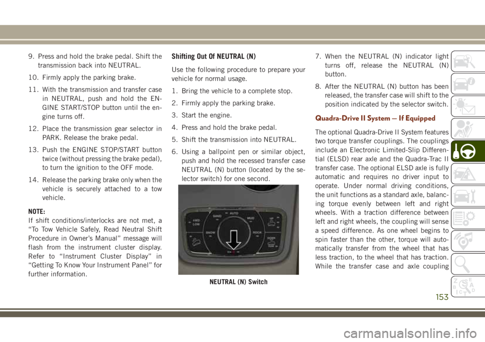
6. Using a ballpoint pen or similar object,
push and hold the recessed transfer case
NEUTRAL (N) button (located by the se-
lector switch) for one second.7. When the NEUTRAL (N) indicator light
turns off, release the NEUTRAL (N)
button.
8. After the NEUTRAL (N) button has been
released, the transfer case will shift to the
position indicated by the selector switch.
Quadra-Drive II System — If Equipped
The optional Quadra-Drive II System features
two torque transfer couplings. The couplings
include an Electronic Limited-Slip Differen-
tial (ELSD) rear axle and the Quadra-Trac II
transfer case. The optional ELSD axle is fully
automatic and requires no driver input to
operate. Under normal driving conditions,
the unit functions as a standard axle, balanc-
ing torque evenly between left and right
wheels. With a traction difference between
left and right wheels, the coupling will sense
a speed difference. As one wheel begins to
spin faster than the other, torque will auto-
matically transfer from the wheel that has
less traction, to the wheel that has traction.
While the transfer case and axle coupling
NEUTRAL (N) Switch
153
Page 194 of 368
Recreational Towing-Two Wheel Drive
Models
DO NOT flat tow this vehicle. Damage to the
drivetrain will result.
Recreational towing (for two-wheel drive
models) is allowed ONLY if the rear wheels
are OFF the ground. This may be accom-
plished using a tow dolly or vehicle trailer. If
using a tow dolly, follow this procedure:
1. Properly secure the dolly to the tow ve-
hicle, following the dolly manufacturer's
instructions.
NOTE:
If vehicle is equipped with Quadra-Lift air
suspension, ensure the vehicle is set to
Normal Ride Height.
2. Drive the rear wheels onto the tow dolly.
3. Firmly apply the parking brake. Shift the
transmission into PARK.
4. Turn the ignition OFF.
5. Properly secure the rear wheels to the
dolly, following the dolly manufacturer’s
instructions.6. Turn the ignition to the ON/RUN mode,
but do not start the engine.
7. Confirm that the steering column is
unlocked.
8. Install a suitable clamping device, de-
signed for towing, to secure the front
wheels in the straight position.
9. Disconnect the negative battery cable,
and secure it away from the battery post.
NOTE:
Disconnecting your vehicle battery will
erase radio presets and may affect other
vehicle settings. It may also trigger vari-
ous fault codes, causing MIL illumination
when the battery is reconnected.
CAUTION!
Towing with the rear wheels on the ground
will cause severe transmission damage.
Damage from improper towing is not cov-
ered under the New Vehicle Limited War-
ranty.
Recreational Towing — Quadra-Trac I
(Single-Speed Transfer Case) Four-Wheel
Drive Models
Recreational towing is not allowed.These
models do not have a NEUTRAL (N) position
in the transfer case.
NOTE:
This vehicle may be towed on a flatbed or
vehicle trailer provided all four wheels areOFF
the ground.
CAUTION!
Towing this vehicle in violation of the
above requirements can cause severe
transmission and/or transfer case damage.
Damage from improper towing is not cov-
ered under the New Vehicle Limited War-
ranty.STARTING AND OPERATING
192
Page 196 of 368
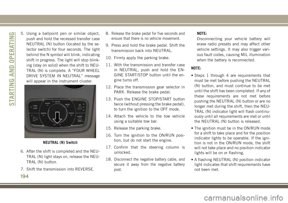
5. Using a ballpoint pen or similar object,
push and hold the recessed transfer case
NEUTRAL (N) button (located by the se-
lector switch) for four seconds. The light
behind the N symbol will blink, indicating
shift in progress. The light will stop blink-
ing (stay on solid) when the shift to NEU-
TRAL (N) is complete. A “FOUR WHEEL
DRIVE SYSTEM IN NEUTRAL” message
will appear in the instrument cluster.
6. After the shift is completed and the NEU-
TRAL (N) light stays on, release the NEU-
TRAL (N) button.
7. Shift the transmission into REVERSE.8.Release the brake pedal for five seconds and
ensure that there is no vehicle movement.
9. Press and hold the brake pedal. Shift the
transmission back into NEUTRAL.
10. Firmly apply the parking brake.
11. With the transmission and transfer case
in NEUTRAL, push and hold the EN-
GINE START/STOP button until the en-
gine turns off.
12. Place the transmission gear selector in
PARK. Release the brake pedal.
13. Push the ENGINE STOP/START button
twice (without pressing the brake pedal),
to turn the ignition to the OFF mode.
14. Attach the vehicle to the tow vehicle
using a suitable tow bar.
15. Release the parking brake.
16. Turn the ignition to the ON/RUN posi-
tion, but do not start the engine.
17. Confirm that the steering column is
unlocked.
18.
Disconnect the negative battery cable, and
secure it away from the negative battery
post.
NOTE:
Disconnecting your vehicle battery will
erase radio presets and may affect other
vehicle settings. It may also trigger vari-
ous fault codes, causing MIL illumination
when the battery is reconnected.
NOTE:
• Steps 1 through 4 are requirements that
must be met before pushing the NEUTRAL
(N) button, and must continue to be met
until the shift has been completed. If any of
these requirements are not met before
pushing the NEUTRAL (N) button or are no
longer met during the shift, then the NEU-
TRAL (N) indicator light will flash continu-
ously until all requirements are met or until
the NEUTRAL (N) button is released.
• The ignition must be in the ON/RUN mode
for a shift to take place and for the position
indicator lights to be operable. If the igni-
tion is not in the ON/RUN mode, the shift
will not take place and no position indicator
lights will be on or flashing.
• A flashing NEUTRAL (N) position indicator
light indicates that shift requirements have
not been met.
NEUTRAL (N) Switch
STARTING AND OPERATING
194
Page 208 of 368
Cavity Cartridge Fuse Micro Fuse Description
F32 30 Amp Pink – Drive Train Control Module
F34 30 Amp Pink – Slip Differential Control
F35 30 Amp Pink – Sunroof - If Equipped
F36 30 Amp Pink – Rear Defroster
F37 25 Amp Clear – Rear Blower Motor — If Equipped
F38 30 Amp Pink – Power Inverter 115V AC — If Equipped
F39 30 Amp Pink – Power Liftgate — If Equipped
F40 – 10 Amp Red Daytime Running Lights/Headlamp Leveling
F42 – 20 Amp Yellow Horn
F44 – 10 Amp Red Diagnostic Port
F45 – 5 Amp Tan Cyber Security Gateway
F49 – 10 Amp Red Integrated Central Stack/Climate Control
F50 – 20 Amp Yellow Air Suspension Control Module/Slip Differential - If
Equipped
F51 – 15 Amp Blue Ignition Node Module/Keyless Ignition/Steering Column
Lock
F53 – 20 Amp Yellow Trailer Tow – Left Turn/Stop Lights — If Equipped
F56 – 15 Amp Blue Additional Content (Diesel engine only)
F57 – 20 Amp Yellow NOX Sensor
F58 – 15 Amp Blue HID Headlamps LH — If Equipped
F59 – 10 Amp Red Purging Pump (Diesel engine only)
F60 – 15 Amp Blue Transmission Control Module
F61 – 10 Amp Red Transmission Control Module/PM Sensor (Diesel engine
only)
IN CASE OF EMERGENCY
206
Page 213 of 368
WARNING!
raised vehicle, take it to a service center
where it can be raised on a lift.
• Only use the jack in the positions indi-
cated and for lifting this vehicle during a
tire change.
• If working on or near a roadway, be
extremely careful of motor traffic.
• To assure that spare tires, flat or in-
flated, are securely stowed, spares must
be stowed with the valve stem facing the
ground.
• The jack should be used on level firm
ground wherever possible.
• It is recommended that the wheels of
the vehicle be chocked, and that no
person should be remain in a vehicle
that is being jacked.
• No person should place any portion of
their body under a vehicle that is sup-
ported by a jack.
CAUTION!
Do not attempt to raise the vehicle by
jacking on locations other than those indi-
cated in the Jacking Instructions for this
vehicle.
1. Remove the spare tire, jack, and tools
from storage.2. Loosen (but do not remove) the wheel lug
nuts by turning them to the left, one turn,
while the wheel is still on the ground.
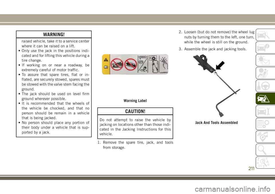
3. Assemble the jack and jacking tools.
Warning Label
Jack And Tools Assembled
211
Page 216 of 368
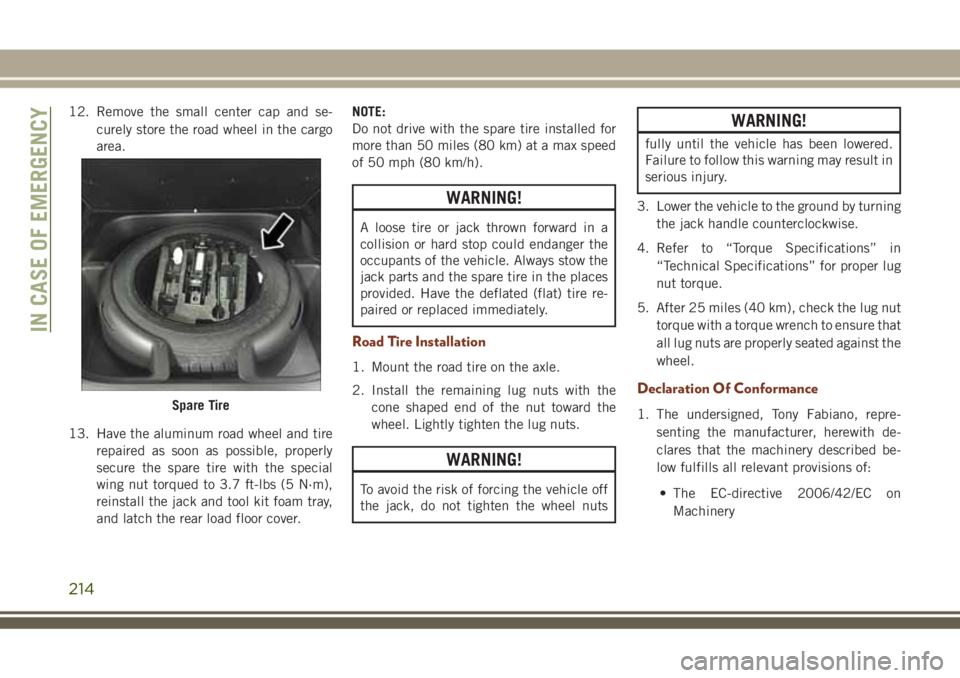
12. Remove the small center cap and se-
curely store the road wheel in the cargo
area.
13. Have the aluminum road wheel and tire
repaired as soon as possible, properly
secure the spare tire with the special
wing nut torqued to 3.7 ft-lbs (5 N·m),
reinstall the jack and tool kit foam tray,
and latch the rear load floor cover.NOTE:
Do not drive with the spare tire installed for
more than 50 miles (80 km) at a max speed
of 50 mph (80 km/h).
WARNING!
A loose tire or jack thrown forward in a
collision or hard stop could endanger the
occupants of the vehicle. Always stow the
jack parts and the spare tire in the places
provided. Have the deflated (flat) tire re-
paired or replaced immediately.
Road Tire Installation
1. Mount the road tire on the axle.
2. Install the remaining lug nuts with the
cone shaped end of the nut toward the
wheel. Lightly tighten the lug nuts.
WARNING!
To avoid the risk of forcing the vehicle off
the jack, do not tighten the wheel nuts
WARNING!
fully until the vehicle has been lowered.
Failure to follow this warning may result in
serious injury.
3. Lower the vehicle to the ground by turning
the jack handle counterclockwise.
4. Refer to “Torque Specifications” in
“Technical Specifications” for proper lug
nut torque.
5. After 25 miles (40 km), check the lug nut
torque with a torque wrench to ensure that
all lug nuts are properly seated against the
wheel.
Declaration Of Conformance
1. The undersigned, Tony Fabiano, repre-
senting the manufacturer, herewith de-
clares that the machinery described be-
low fulfills all relevant provisions of:
• The EC-directive 2006/42/EC on
MachinerySpare Tire
IN CASE OF EMERGENCY
214
Page 223 of 368
CAUTION!
Driving with a hot cooling system could
damage your vehicle. If the temperature
gauge reads HOT (H), pull over and stop
the vehicle. Idle the vehicle with the air
conditioner turned off until the pointer
drops back into the normal range. If the
pointer remains on HOT (H), and you hear
continuous chimes, turn the engine off
immediately and call for service.
MANUAL PARK RELEASE
WARNING!
Always secure your vehicle by fully apply-
ing the parking brake before activating the
Manual Park Release. In addition, you
should be seated in the driver’s seat with
your foot firmly on the brake pedal when
activating the Manual Park Release. Acti-
vating the Manual Park Release will allow
your vehicle to roll away if it is not secured
by the parking brake, or by proper connec-
tion to a tow vehicle. Activating the
WARNING!
Manual Park Release on an unsecured
vehicle could lead to serious injury or
death for those in or around the vehicle.
In order to move the vehicle in cases where
the transmission will not shift out of PARK
(such as a dead battery), a Manual Park
Release is available.
Follow these steps to use the Manual Park
Release:
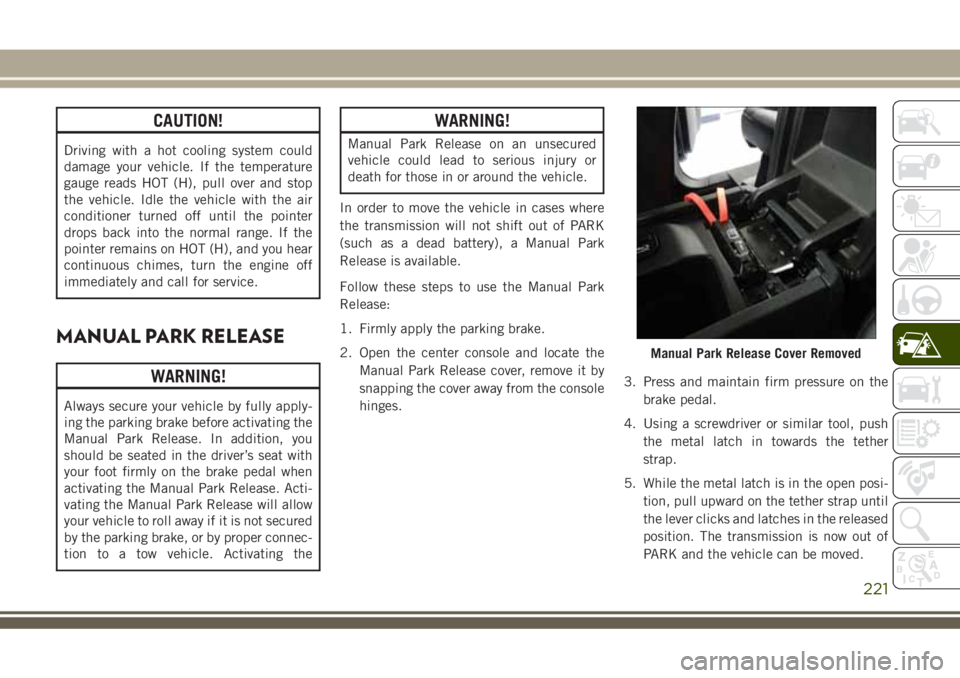
1. Firmly apply the parking brake.
2. Open the center console and locate the
Manual Park Release cover, remove it by
snapping the cover away from the console
hinges.3. Press and maintain firm pressure on the
brake pedal.
4. Using a screwdriver or similar tool, push
the metal latch in towards the tether
strap.
5. While the metal latch is in the open posi-
tion, pull upward on the tether strap until
the lever clicks and latches in the released
position. The transmission is now out of
PARK and the vehicle can be moved.
Manual Park Release Cover Removed
221