brake light JEEP GRAND CHEROKEE 2018 Owner handbook (in English)
[x] Cancel search | Manufacturer: JEEP, Model Year: 2018, Model line: GRAND CHEROKEE, Model: JEEP GRAND CHEROKEE 2018Pages: 368, PDF Size: 5.72 MB
Page 154 of 368
NOTE:
• If shift conditions/interlocks are not met, or
a transfer case motor temperature protec-
tion condition exists, a “For 4x4 High Slow
Below 3 mph (5 km/h) Put Trans in N push
4 Low” message will flash from the instru-
ment cluster display. Refer to “Instrument
Cluster Display” in “Getting To Know Your
Instrument Panel” for further information.
• Shifting into or out of 4WD LOW is possible
with the vehicle completely stopped; how-
ever, difficulty may occur due to the mating
clutch teeth not being properly aligned.
Several attempts may be required for
clutch teeth alignment and shift comple-
tion to occur. The preferred method is with
the vehicle rolling 0 to 3 mph (0 to 5 km/h).
If the vehicle is moving faster than 3 mph
(5 km/h), the transfer case will not allow
the shift.
Shifting Into NEUTRAL (N)
WARNING!
You or others could be injured or killed if
you leave the vehicle unattended with the
WARNING!
transfer case in the NEUTRAL (N) position
without first fully engaging the parking
brake. The NEUTRAL (N) position disen-
gages both the front and rear drive shafts
from the powertrain and will allow the
vehicle to roll, even if the transmission is
in PARK. The parking brake should always
be applied when the driver is not in the
vehicle.
1. Bring the vehicle to a complete stop, with
the engine running.
2. Press and hold the brake pedal.
3. Shift the transmission into NEUTRAL.
4. If vehicle is equipped with Quadra-Lift air
suspension, ensure the vehicle is set to
Normal Ride Height.
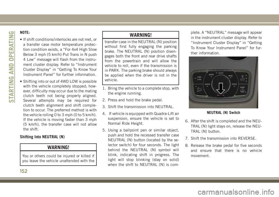
5. Using a ballpoint pen or similar object,
push and hold the recessed transfer case
NEUTRAL (N) button (located by the se-
lector switch) for four seconds. The light
behind the NEUTRAL (N) symbol will
blink, indicating shift in progress. The
light will stop blinking (stay on solid)
when the shift to NEUTRAL (N) is com-plete. A “NEUTRAL” message will appear
in the instrument cluster display. Refer to
“Instrument Cluster Display” in “Getting
To Know Your Instrument Panel” for fur-
ther information.
6. After the shift is completed and the NEU-
TRAL (N) light stays on, release the NEU-
TRAL (N) button.
7. Shift the transmission into REVERSE.
8. Release the brake pedal for five seconds
and ensure that there is no vehicle
movement.
NEUTRAL (N) Switch
STARTING AND OPERATING
152
Page 155 of 368
9. Press and hold the brake pedal. Shift the
transmission back into NEUTRAL.
10. Firmly apply the parking brake.
11. With the transmission and transfer case
in NEUTRAL, push and hold the EN-
GINE START/STOP button until the en-
gine turns off.
12. Place the transmission gear selector in
PARK. Release the brake pedal.
13. Push the ENGINE STOP/START button
twice (without pressing the brake pedal),
to turn the ignition to the OFF mode.
14. Release the parking brake only when the
vehicle is securely attached to a tow
vehicle.
NOTE:
If shift conditions/interlocks are not met, a
“To Tow Vehicle Safely, Read Neutral Shift
Procedure in Owner’s Manual” message will
flash from the instrument cluster display.
Refer to “Instrument Cluster Display” in
“Getting To Know Your Instrument Panel” for
further information.Shifting Out Of NEUTRAL (N)
Use the following procedure to prepare your
vehicle for normal usage.
1. Bring the vehicle to a complete stop.
2. Firmly apply the parking brake.
3. Start the engine.
4. Press and hold the brake pedal.
5. Shift the transmission into NEUTRAL.
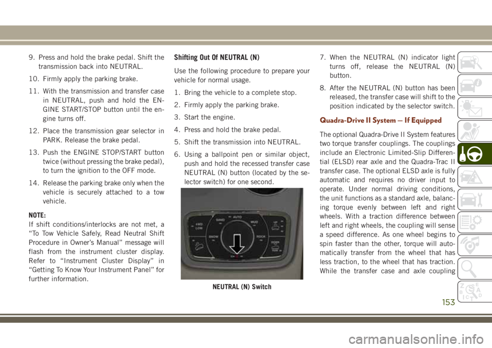
6. Using a ballpoint pen or similar object,
push and hold the recessed transfer case
NEUTRAL (N) button (located by the se-
lector switch) for one second.7. When the NEUTRAL (N) indicator light
turns off, release the NEUTRAL (N)
button.
8. After the NEUTRAL (N) button has been
released, the transfer case will shift to the
position indicated by the selector switch.
Quadra-Drive II System — If Equipped
The optional Quadra-Drive II System features
two torque transfer couplings. The couplings
include an Electronic Limited-Slip Differen-
tial (ELSD) rear axle and the Quadra-Trac II
transfer case. The optional ELSD axle is fully
automatic and requires no driver input to
operate. Under normal driving conditions,
the unit functions as a standard axle, balanc-
ing torque evenly between left and right
wheels. With a traction difference between
left and right wheels, the coupling will sense
a speed difference. As one wheel begins to
spin faster than the other, torque will auto-
matically transfer from the wheel that has
less traction, to the wheel that has traction.
While the transfer case and axle coupling
NEUTRAL (N) Switch
153
Page 169 of 368
• The ACC system applies the brake down to
a full stop when following a target vehicle.
If an ACC host vehicle follows a target
vehicle to a standstill, the host vehicle will
release the vehicle brakes two seconds af-
ter coming to a full stop.
• The ACC system maintains set speed when
driving up hill and down hill. However, a
slight speed change on moderate hills is
normal. In addition, downshifting may oc-
cur while climbing uphill or descending
downhill. This is normal operation and nec-
essary to maintain set speed. When driving
up hill and down hill, the ACC system will
cancel if the braking temperature exceeds
normal range (overheated).
To Increase Speed
While ACC is set, you can increase the set
speed by pushing the SET(+)button.
The driver's preferred units can be selected
through the instrument panel settings if
equipped. Refer to “Getting To Know Your
Instrument Panel” in the Owner’s Manual for
more information. The speed increment
shown is dependant on the speed of U.S.
(mph) or Metric (km/h) units:U.S. Speed (mph)
• Pushing the SET(+)button once will result
in a 1 mph increase in set speed. Each
subsequent tap of the button results in an
increase of 1 mph.
• If the button is continually pushed, the set
speed will continue to increase in 5 mph
increments until the button is released. The
increase in set speed is reflected in the
instrument cluster display.
Metric Speed (km/h)
• Pushing the SET(+)button once will result
in a 1 km/h increase in set speed. Each
subsequent tap of the button results in an
increase of 1 km/h.
• If the button is continually pushed, the set
speed will continue to increase in 10 km/h
increments until the button is released. The
increase in set speed is reflected in the
instrument cluster display.
To Decrease Speed
While ACC is set, the set speed can be de-
creased by pushing the SET(-)button.The driver's preferred units can be selected
through the instrument panel settings if
equipped. Refer to “Getting To Know Your
Instrument Panel” in the Owner’s Manual for
more information. The speed increment
shown is dependant on the speed of U.S.
(mph) or Metric (km/h) units:
U.S. Speed (mph)
• Pushing the SET(-)button once will result
in a 1 mph decrease in set speed. Each
subsequent tap of the button results in a
decrease of 1 mph.
• If the button is continually pushed, the set
speed will continue to decrease in 5 mph
decrements until the button is released.
The decrease in set speed is reflected in the
instrument cluster display.
Metric Speed (km/h)
• Pushing the SET(-)button once will result
in a 1 km/h decrease in set speed. Each
subsequent tap of the button results in a
decrease of 1 km/h.
167
Page 175 of 368
Activation/Deactivation
The ParkSense Park Assist system provides
visual and audible indications of the distance
between the rear and/or front fascia and a
detected obstacle when backing up or moving
forward, e.g. during a parking maneuver. If
your vehicle is equipped with an Automatic
Transmission, the vehicle brakes may be au-
tomatically applied and released when per-
forming a reverse parking maneuver if the
system detects a possible collision with an
obstacle.
ParkSense can be active only when the gear
selector is in REVERSE or DRIVE. If
ParkSense is enabled at one of these gear
selector positions, the system will remain
active until the vehicle speed is increased to
approximately 7 mph (11 km/h) or above. A
display warning will appear in the instrument
cluster display indicating the vehicle is aboveParkSense operating speed. The system will
become active again if the vehicle speed is
decreased to speeds less than approximately
6 mph (9 km/h).
Engagement/Disengagement
To disengage the system, push the ParkSense
switch, located on the switch panel below the
Uconnect display.
When the system passes from engaged to
disengaged and vice versa, it is always ac-
companied by a dedicated message in the
instrument cluster display.
System engaged:ParkSense switch LED off.
System disengaged:ParkSense switch LED on
constantly.
The ParkSense switch LED lights up also in
the case of a ParkSense system failure. If the
button is pushed with a system failure, the
ParkSense switch LED flashes for about five
seconds, then it stays on constantly.After the ParkSense has been disengaged, it
will stay in this condition until the following
engagement, even if the ignition device
passes from ON/RUN to OFF and then again
to ON/RUN.Operation With A Trailer
The operation of the sensors is automatically
deactivated when the trailer's electric plug is
inserted in the vehicle's tow hook socket. The
sensors are automatically reactivated when
the trailer's cable plug is removed.
General Warnings
If “PARKSENSE UNAVAILABLE WIPE REAR
SENSORS" or "PARKSENSE UNAVAILABLE
WIPE FRONT SENSORS” appears in the in-
strument cluster display, clean the
ParkSense sensors with water, car wash soap
and a soft cloth. Do not use rough or hard
cloths. Do not scratch or poke the sensors.
Otherwise, you could damage the sensors.
173
Page 196 of 368
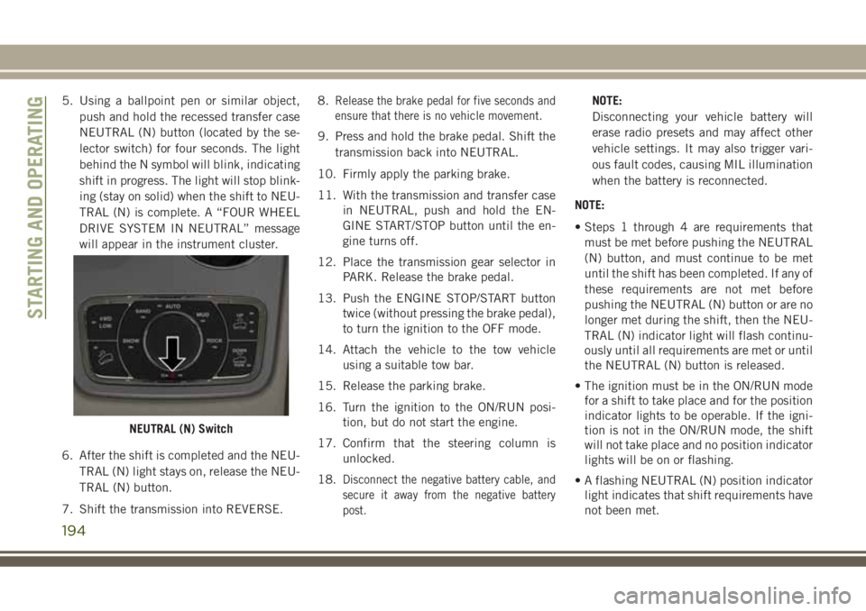
5. Using a ballpoint pen or similar object,
push and hold the recessed transfer case
NEUTRAL (N) button (located by the se-
lector switch) for four seconds. The light
behind the N symbol will blink, indicating
shift in progress. The light will stop blink-
ing (stay on solid) when the shift to NEU-
TRAL (N) is complete. A “FOUR WHEEL
DRIVE SYSTEM IN NEUTRAL” message
will appear in the instrument cluster.
6. After the shift is completed and the NEU-
TRAL (N) light stays on, release the NEU-
TRAL (N) button.
7. Shift the transmission into REVERSE.8.Release the brake pedal for five seconds and
ensure that there is no vehicle movement.
9. Press and hold the brake pedal. Shift the
transmission back into NEUTRAL.
10. Firmly apply the parking brake.
11. With the transmission and transfer case
in NEUTRAL, push and hold the EN-
GINE START/STOP button until the en-
gine turns off.
12. Place the transmission gear selector in
PARK. Release the brake pedal.
13. Push the ENGINE STOP/START button
twice (without pressing the brake pedal),
to turn the ignition to the OFF mode.
14. Attach the vehicle to the tow vehicle
using a suitable tow bar.
15. Release the parking brake.
16. Turn the ignition to the ON/RUN posi-
tion, but do not start the engine.
17. Confirm that the steering column is
unlocked.
18.
Disconnect the negative battery cable, and
secure it away from the negative battery
post.
NOTE:
Disconnecting your vehicle battery will
erase radio presets and may affect other
vehicle settings. It may also trigger vari-
ous fault codes, causing MIL illumination
when the battery is reconnected.
NOTE:
• Steps 1 through 4 are requirements that
must be met before pushing the NEUTRAL
(N) button, and must continue to be met
until the shift has been completed. If any of
these requirements are not met before
pushing the NEUTRAL (N) button or are no
longer met during the shift, then the NEU-
TRAL (N) indicator light will flash continu-
ously until all requirements are met or until
the NEUTRAL (N) button is released.
• The ignition must be in the ON/RUN mode
for a shift to take place and for the position
indicator lights to be operable. If the igni-
tion is not in the ON/RUN mode, the shift
will not take place and no position indicator
lights will be on or flashing.
• A flashing NEUTRAL (N) position indicator
light indicates that shift requirements have
not been met.
NEUTRAL (N) Switch
STARTING AND OPERATING
194
Page 197 of 368
• If the vehicle is equipped with Quadra-Lift
air suspension, the engine should be
started and left running for a minimum of
60 seconds (with all the doors closed) at
least once every 24 hours. This process
allows the air suspension to adjust the
vehicle’s ride height to compensate for
temperature effects.
Shifting Out Of NEUTRAL (N)
Use the following procedure to prepare your
vehicle for normal usage.
1. Bring the vehicle to a complete stop, leav-
ing it connected to the tow vehicle.
2. Firmly apply the parking brake.
3. Reconnect the negative battery cable.
4. Turn the ignition to the LOCK/OFF mode.
5. Start the engine.
6. Press and hold the brake pedal.
7. Shift the transmission into NEUTRAL.
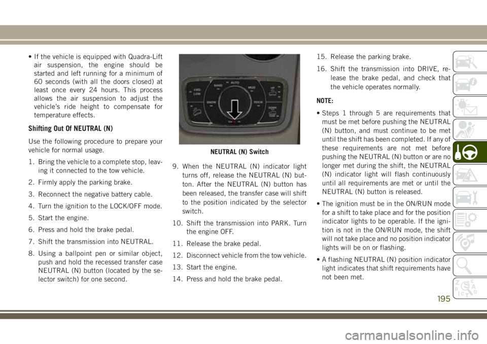
8. Using a ballpoint pen or similar object,
push and hold the recessed transfer case
NEUTRAL (N) button (located by the se-
lector switch) for one second.9. When the NEUTRAL (N) indicator light
turns off, release the NEUTRAL (N) but-
ton. After the NEUTRAL (N) button has
been released, the transfer case will shift
to the position indicated by the selector
switch.
10. Shift the transmission into PARK. Turn
the engine OFF.
11. Release the brake pedal.
12. Disconnect vehicle from the tow vehicle.
13. Start the engine.
14. Press and hold the brake pedal.15. Release the parking brake.
16. Shift the transmission into DRIVE, re-
lease the brake pedal, and check that
the vehicle operates normally.
NOTE:
• Steps 1 through 5 are requirements that
must be met before pushing the NEUTRAL
(N) button, and must continue to be met
until the shift has been completed. If any of
these requirements are not met before
pushing the NEUTRAL (N) button or are no
longer met during the shift, the NEUTRAL
(N) indicator light will flash continuously
until all requirements are met or until the
NEUTRAL (N) button is released.
• The ignition must be in the ON/RUN mode
for a shift to take place and for the position
indicator lights to be operable. If the igni-
tion is not in the ON/RUN mode, the shift
will not take place and no position indicator
lights will be on or flashing.
• A flashing NEUTRAL (N) position indicator
light indicates that shift requirements have
not been met.
NEUTRAL (N) Switch
195
Page 207 of 368
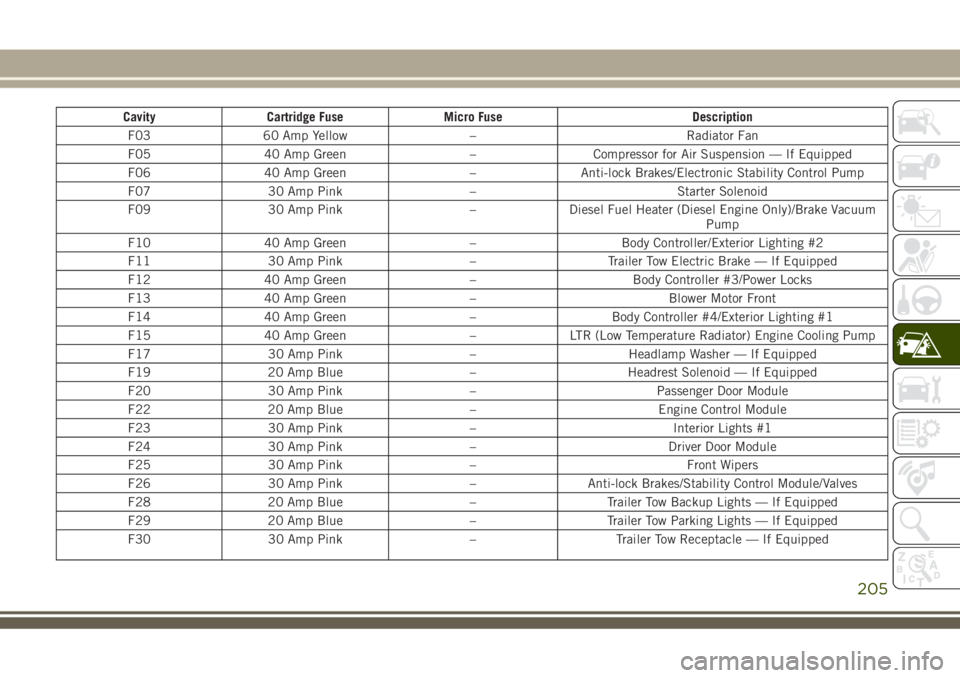
Cavity Cartridge Fuse Micro Fuse Description
F03 60 Amp Yellow – Radiator Fan
F05 40 Amp Green – Compressor for Air Suspension — If Equipped
F06 40 Amp Green – Anti-lock Brakes/Electronic Stability Control Pump
F07 30 Amp Pink – Starter Solenoid
F09 30 Amp Pink – Diesel Fuel Heater (Diesel Engine Only)/Brake Vacuum
Pump
F10 40 Amp Green – Body Controller/Exterior Lighting #2
F11 30 Amp Pink – Trailer Tow Electric Brake — If Equipped
F12 40 Amp Green – Body Controller #3/Power Locks
F13 40 Amp Green – Blower Motor Front
F14 40 Amp Green – Body Controller #4/Exterior Lighting #1
F15 40 Amp Green – LTR (Low Temperature Radiator) Engine Cooling Pump
F17 30 Amp Pink – Headlamp Washer — If Equipped
F19 20 Amp Blue – Headrest Solenoid — If Equipped
F20 30 Amp Pink – Passenger Door Module
F22 20 Amp Blue – Engine Control Module
F23 30 Amp Pink – Interior Lights #1
F24 30 Amp Pink – Driver Door Module
F25 30 Amp Pink – Front Wipers
F26 30 Amp Pink – Anti-lock Brakes/Stability Control Module/Valves
F28 20 Amp Blue – Trailer Tow Backup Lights — If Equipped
F29 20 Amp Blue – Trailer Tow Parking Lights — If Equipped
F30 30 Amp Pink – Trailer Tow Receptacle — If Equipped
205
Page 209 of 368
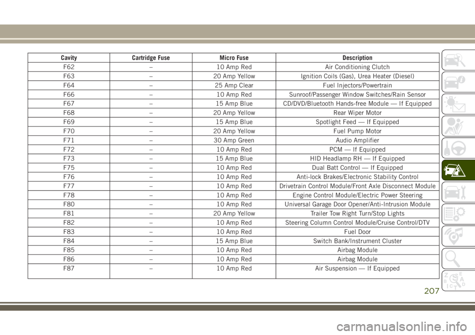
Cavity Cartridge Fuse Micro Fuse Description
F62 – 10 Amp Red Air Conditioning Clutch
F63 – 20 Amp Yellow Ignition Coils (Gas), Urea Heater (Diesel)
F64 – 25 Amp Clear Fuel Injectors/Powertrain
F66 – 10 Amp Red Sunroof/Passenger Window Switches/Rain Sensor
F67 – 15 Amp Blue CD/DVD/Bluetooth Hands-free Module — If Equipped
F68 – 20 Amp Yellow Rear Wiper Motor
F69 – 15 Amp Blue Spotlight Feed — If Equipped
F70 – 20 Amp Yellow Fuel Pump Motor
F71 – 30 Amp Green Audio Amplifier
F72 – 10 Amp Red PCM — If Equipped
F73 – 15 Amp Blue HID Headlamp RH — If Equipped
F75 – 10 Amp Red Dual Batt Control — If Equipped
F76 – 10 Amp Red Anti-lock Brakes/Electronic Stability Control
F77 – 10 Amp Red Drivetrain Control Module/Front Axle Disconnect Module
F78 – 10 Amp Red Engine Control Module/Electric Power Steering
F80 – 10 Amp Red Universal Garage Door Opener/Anti-Intrusion Module
F81 – 20 Amp Yellow Trailer Tow Right Turn/Stop Lights
F82 – 10 Amp Red Steering Column Control Module/Cruise Control/DTV
F83 – 10 Amp Red Fuel Door
F84 – 15 Amp Blue Switch Bank/Instrument Cluster
F85 – 10 Amp Red Airbag Module
F86 – 10 Amp Red Airbag Module
F87 – 10 Amp Red Air Suspension — If Equipped
207
Page 232 of 368
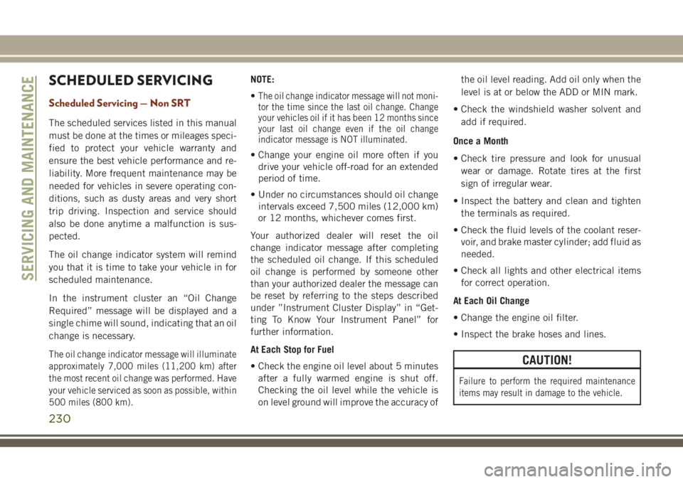
SCHEDULED SERVICING
Scheduled Servicing — Non SRT
The scheduled services listed in this manual
must be done at the times or mileages speci-
fied to protect your vehicle warranty and
ensure the best vehicle performance and re-
liability. More frequent maintenance may be
needed for vehicles in severe operating con-
ditions, such as dusty areas and very short
trip driving. Inspection and service should
also be done anytime a malfunction is sus-
pected.
The oil change indicator system will remind
you that it is time to take your vehicle in for
scheduled maintenance.
In the instrument cluster an “Oil Change
Required” message will be displayed and a
single chime will sound, indicating that an oil
change is necessary.
The oil change indicator message will illuminate
approximately 7,000 miles (11,200 km) after
the most recent oil change was performed. Have
your vehicle serviced as soon as possible, within
500 miles (800 km).
NOTE:
•
The oil change indicator message will not moni-
tor the time since the last oil change. Change
your vehicles oil if it has been 12 months since
your last oil change even if the oil change
indicator message is NOT illuminated.
• Change your engine oil more often if you
drive your vehicle off-road for an extended
period of time.
• Under no circumstances should oil change
intervals exceed 7,500 miles (12,000 km)
or 12 months, whichever comes first.
Your authorized dealer will reset the oil
change indicator message after completing
the scheduled oil change. If this scheduled
oil change is performed by someone other
than your authorized dealer the message can
be reset by referring to the steps described
under ”Instrument Cluster Display” in “Get-
ting To Know Your Instrument Panel” for
further information.
At Each Stop for Fuel
• Check the engine oil level about 5 minutes
after a fully warmed engine is shut off.
Checking the oil level while the vehicle is
on level ground will improve the accuracy ofthe oil level reading. Add oil only when the
level is at or below the ADD or MIN mark.
• Check the windshield washer solvent and
add if required.
Once a Month
• Check tire pressure and look for unusual
wear or damage. Rotate tires at the first
sign of irregular wear.
• Inspect the battery and clean and tighten
the terminals as required.
• Check the fluid levels of the coolant reser-
voir, and brake master cylinder; add fluid as
needed.
• Check all lights and other electrical items
for correct operation.
At Each Oil Change
• Change the engine oil filter.
• Inspect the brake hoses and lines.
CAUTION!
Failure to perform the required maintenance
items may result in damage to the vehicle.
SERVICING AND MAINTENANCE
230
Page 237 of 368
• Check the fluid levels of the coolant reser-
voir, engine oil, brake master cylinder, and
add as needed.
• Check all lights and other electrical items
for correct operation.At Each Oil Change
• Change the engine oil filter.
• Inspect the brake hoses and lines.CAUTION!
Failure to perform the required mainte-
nance items may result in damage to the
vehicle.
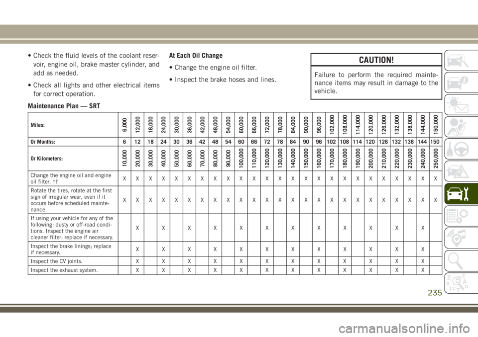
Maintenance Plan — SRT
Miles:6,000
12,000
18,000
24,000
30,000
36,000
42,000
48,000
54,000
60,000
66,000
72,000
78,000
84,000
90,000
96,000
102,000
108,000
114,000
120,000
126,000
132,000
138,000
144,000
150,000
Or Months: 6 12 18 24 30 36 42 48 54 60 66 72 78 84 90 96 102 108 114 120 126 132 138 144 150
Or Kilometers:
10,000
20,000
30,000
40,000
50,000
60,000
70,000
80,000
90,000
100,000
110,000
120,000
130,000
140,000
150,000
160,000
170,000
180,000
190,000
200,000
210,000
220,000
230,000
240,000
250,000
Change the engine oil and engine
oil filter. ††XXXXXXXXXXXXXXXXXXXXXXXXX
Rotate the tires, rotate at the first
sign of irregular wear, even if it
occurs before scheduled mainte-
nance.XXXXXXXXXXXXXXXXXXXXXXXXX
If using your vehicle for any of the
following: dusty or off-road condi-
tions. Inspect the engine air
cleaner filter; replace if necessary.XXXXXXXXXXXX
Inspect the brake linings; replace
if necessary.XXXXXXXXXXXX
Inspect the CV joints. X X X X X X X X X X X X
Inspect the exhaust system. X X X X X X X X X X X X
235