fuel pump JEEP GRAND CHEROKEE 2018 Owner handbook (in English)
[x] Cancel search | Manufacturer: JEEP, Model Year: 2018, Model line: GRAND CHEROKEE, Model: JEEP GRAND CHEROKEE 2018Pages: 368, PDF Size: 5.72 MB
Page 119 of 368
Your vehicle may also be designed to perform
any of these other functions in response to
the Enhanced Accident Response System:
• Turn off the Fuel Filter Heater, Turn off the
HVAC Blower Motor, Close the HVAC Circu-
lation Door
• Cut off battery power to the:
– Engine
– Electric Motor (if equipped)
– Electric power steering
– Brake booster
– Electric park brake
– Automatic transmission gear selector
– Horn
– Front wiper
– Headlamp washer pumpNOTE:
After an accident, remember to cycle the
ignition to the STOP (OFF/LOCK) position
and remove the key from the ignition switch
to avoid draining the battery. Carefully check
the vehicle for fuel leaks in the engine com-
partment and on the ground near the engine
compartment and fuel tank before resetting
the system and starting the engine. If there
are no fuel leaks or damage to the vehicle
electrical devices (e.g. headlights) after an
accident, reset the system by following the
procedure described below.
Enhanced Accident Response System Reset
Procedure
In order to reset the Enhanced Accident Re-
sponse System functions after an event, the
ignition switch must be changed from igni-
tion START or ON/RUN to ignition OFF. Care-
fully check the vehicle for fuel leaks in the
engine compartment and on the ground near
the engine compartment and fuel tank before
resetting the system and starting the engine.
Maintaining Your Air Bag System
WARNING!
• Modifications to any part of the air bag
system could cause it to fail when you
need it. You could be injured if the air
bag system is not there to protect you.
Do not modify the components or wiring,
including adding any kind of badges or
stickers to the steering wheel hub trim
cover or the upper right side of the in-
strument panel. Do not modify the front
bumper, vehicle body structure, or add
aftermarket side steps or running
boards.
• It is dangerous to try to repair any part of
the air bag system yourself. Be sure to
tell anyone who works on your vehicle
that it has an air bag system.
• Do not attempt to modify any part of your
air bag system. The air bag may inflate
accidentally or may not function prop-
erly if modifications are made. Take your
vehicle to an authorized dealer for any
air bag system service. If your seat, in-
cluding your trim cover and cushion,
117
Page 142 of 368
Automatic Transmission
Start the engine with the transmission gear
selector in the PARK position. Apply the
brake before shifting to any driving range.
Normal Starting
Observe the instrument panel cluster lights
when starting the engine.
NOTE:
Normal starting of either a cold or a warm
engine is obtained without pumping or press-
ing the accelerator pedal
1. Always apply the parking brake.
2. Press and hold the brake pedal while
pushing the ENGINE START/STOP button
once.
NOTE:
A delay of the start of up to five seconds is
possible under very cold conditions. The
"Wait to Start" telltale will be illuminated
during the pre-heat process, When the
engine Wait To Start light goes off the
engine will automatically crank.
CAUTION!
If the “Water in Fuel Indicator Light” re-
mains on, DO NOT START engine before
you drain the water from the fuel filters to
avoid engine damage. Refer to “Draining
Fuel/Water Separator Filter” in “Servicing
And Maintenance” in your Diesel Supple-
ment for further information, which can be
found with your online Owner’s Informa-
tion.
3. The system will automatically engage the
starter to crank the engine. If the vehicle
fails to start, the starter will disengage
automatically after 25 seconds.
4. If you wish to stop the cranking of the
engine prior to the engine starting, push
the button again.
5. Check that the oil pressure warning light
has turned off.
6. Release the parking brake.
STOP/START SYSTEM — IF
EQUIPPED
The Stop/Start function is developed to re-
duce fuel consumption. The system will stop
the engine automatically during a vehicle
stop if the required conditions are met. Re-
leasing the brake pedal or pressing the accel-
erator pedal will automatically re-start the
engine.
This vehicle has been upgraded with a heavy
duty starter, enhanced battery, and other up-
graded engine parts, to handle the additional
engine starts.
Automatic Mode
The Stop/Start feature is enabled
after every normal customer en-
gine start. At that time, the sys-
tem will go into STOP/START
READY and if all other conditions are met,
can go into a STOP/START AUTOSTOP AC-
TIVE “Autostop” mode.
STARTING AND OPERATING
140
Page 180 of 368

3. Ensure funnel is inserted fully to hold
flapper doors open.
4. Pour fuel into funnel opening.
5. Remove funnel from filler pipe, clean off
prior to putting back in the spare tire
storage area.
WARNING!
• Never have any smoking materials lit in
or near the vehicle when the fuel door is
open or the tank is being filled.
• Never add fuel when the engine is run-
ning. This is in violation of most coun-
tries regulations and may cause the
“Malfunction Indicator Light” to turn
on.
• A fire may result if fuel is pumped into a
portable container that is inside of a
vehicle. You could be burned. Always
place fuel containers on the ground
while filling.
CAUTION!
To avoid fuel spillage and overfilling, do
not “top off” the fuel tank after filling.
Emergency Fuel Filler Door Release
If you are unable to open the fuel filler door,
use the fuel filler door emergency release.
1. Open the liftgate.2. Push the inboard edge of the left storage
bin to the center, this will pop up the
outboard edge.
3. Grab popped up outboard edge with other
hand to disengage snaps.
4. Remove the storage bin.
5. Pull the release cable to open the fuel
door, push the release cable back to the
home position to re-seat the fuel door
latch to the closed position.
Fuel Filler
Storage Bin Location
STARTING AND OPERATING
178
Page 183 of 368
WARNING!
• Never have any smoking materials lit in
or near the vehicle when the fuel door is
open or the tank is being filled.
• Never add fuel when the engine is run-
ning. This is in violation of most coun-
tries regulations and may cause the
“Malfunction Indicator Light” to turn
on.
• A fire may result if fuel is pumped into a
portable container that is inside of a
vehicle. You could be burned. Always
place fuel containers on the ground
while filling.
CAUTION!
To avoid fuel spillage and overfilling, do
not “top off” the fuel tank after filling.
Avoid Using Contaminated Fuel
Fuel that is contaminated by water or dirt can
cause severe damage to the engine fuel sys-
tem. Proper maintenance of the engine fuelfilter and fuel tank is essential. Refer to
“Dealer Service” in “Servicing And Mainte-
nance” in your Owner’s Manual for further
information.
Bulk Fuel Storage — Diesel Fuel
If you store quantities of fuel, good mainte-
nance of the stored fuel is also essential. Fuel
contaminated with water will promote the
growth of “microbes.” These microbes form
“slime” that will clog the fuel filtration sys-
tem and lines. Drain condensation from the
supply tank and change the line filter on a
regular basis.
NOTE:
When a diesel engine is allowed to run out of
fuel, air is pulled into the fuel system.
If the vehicle will not start, refer to “Dealer
Service / Priming If The Engine Has Run Out
Of Fuel” in “Servicing And Maintenance” in
your Owner’s Manual for further information.
WARNING!
Do not open the high pressure fuel system
with the engine running. Engine operation
WARNING!
causes high fuel pressure. High pressure
fuel spray can cause serious injury or
death.
Diesel Exhaust Fluid
Your vehicle is equipped with a Selective
Catalytic Reduction system to meet the very
stringent diesel emissions standards required
by the Environmental Protection Agency.
The purpose of the SCR system is to reduce
levels of NOx (oxides of nitrogen emitted from
engines) that are harmful to our health and
the environment to a near-zero level. A small
quantity of Diesel Exhaust Fluid (DEF) is
injected into the exhaust upstream of a cata-
lyst where, when vaporized, it converts smog-
forming nitrogen oxides (NOx) into harmless
nitrogen (N2) and water vapor (H2O), two
natural components of the air we breathe.
You can operate with the comfort that your
vehicle is contributing to a cleaner, healthier
world environment for this and generations to
come.
181
Page 184 of 368
System Overview
This vehicle is equipped with a Diesel Ex-
haust Fluid (DEF) injection system and a
Selective Catalytic Reduction (SCR) catalyst
to meet the emission requirements.
The DEF injection system consists of the
following components:
• DEF tank
• DEF pump
• DEF injector
• Electronically-heated DEF lines
• NOx sensors
• Temperature sensors
• SCR catalyst
The DEF injection system and SCR catalyst
enable the achievement of diesel emissions
requirements; while maintaining outstanding
fuel economy, drivability, torque and power
ratings.Refer to “Instrument Cluster Display” in
“Getting To Know Your Instrument Panel” for
system messages and warnings.
NOTE:
• Your vehicle is equipped with a DEF injec-
tion system. You may occasionally hear an
audible clicking noise from under the ve-
hicle at a stop. This is normal operation.
• The DEF pump will run for a period of time
after engine shutdown to purge the DEF
system. This is normal operation and may
be audible from the rear of the vehicle.
Diesel Exhaust Fluid Storage
Diesel Exhaust Fluid (DEF) is considered a
very stable product with a long shelf life. If
DEF is kept in temperatures between 10° and
90°F (-12° and 32°C), it will last a minimum
of one year.
DEF is subject to freezing at the lowest tem-
peratures. For example, DEF may freeze at
temperatures at or below 12° F (-11° C). The
system has been designed to operate in this
environment.
NOTE:
When working with DEF, it is important to
know that:
• Any containers or parts that come into con-
tact with DEF must be DEF compatible
(plastic or stainless steel). Copper, brass,
aluminum, iron or non-stainless steel
should be avoided as they are subject to
corrosion by DEF.
• If DEF is spilled, it should be wiped up
completely.
STARTING AND OPERATING
182
Page 186 of 368
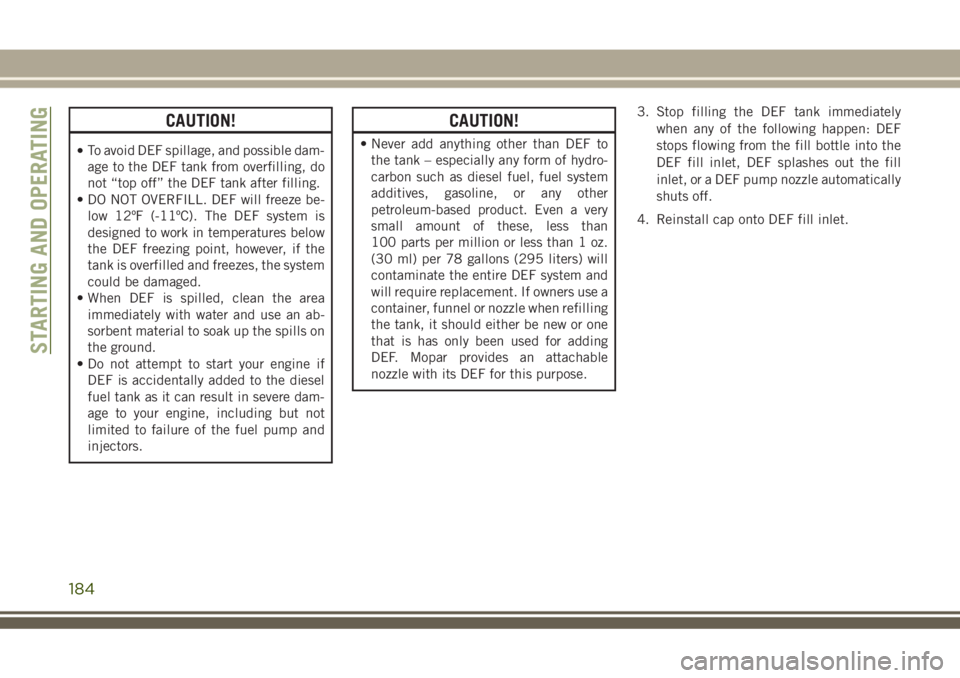
CAUTION!
•To avoid DEF spillage, and possible dam-
age to the DEF tank from overfilling, do
not “top off” the DEF tank after filling.
• DO NOT OVERFILL. DEF will freeze be-
low 12ºF (-11ºC). The DEF system is
designed to work in temperatures below
the DEF freezing point, however, if the
tank is overfilled and freezes, the system
could be damaged.
• When DEF is spilled, clean the area
immediately with water and use an ab-
sorbent material to soak up the spills on
the ground.
• Do not attempt to start your engine if
DEF is accidentally added to the diesel
fuel tank as it can result in severe dam-
age to your engine, including but not
limited to failure of the fuel pump and
injectors.
CAUTION!
• Never add anything other than DEF to
the tank – especially any form of hydro-
carbon such as diesel fuel, fuel system
additives, gasoline, or any other
petroleum-based product. Even a very
small amount of these, less than
100 parts per million or less than 1 oz.
(30 ml) per 78 gallons (295 liters) will
contaminate the entire DEF system and
will require replacement. If owners use a
container, funnel or nozzle when refilling
the tank, it should either be new or one
that is has only been used for adding
DEF. Mopar provides an attachable
nozzle with its DEF for this purpose.3. Stop filling the DEF tank immediately
when any of the following happen: DEF
stops flowing from the fill bottle into the
DEF fill inlet, DEF splashes out the fill
inlet, or a DEF pump nozzle automatically
shuts off.
4. Reinstall cap onto DEF fill inlet.
STARTING AND OPERATING
184
Page 207 of 368
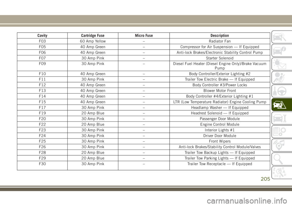
Cavity Cartridge Fuse Micro Fuse Description
F03 60 Amp Yellow – Radiator Fan
F05 40 Amp Green – Compressor for Air Suspension — If Equipped
F06 40 Amp Green – Anti-lock Brakes/Electronic Stability Control Pump
F07 30 Amp Pink – Starter Solenoid
F09 30 Amp Pink – Diesel Fuel Heater (Diesel Engine Only)/Brake Vacuum
Pump
F10 40 Amp Green – Body Controller/Exterior Lighting #2
F11 30 Amp Pink – Trailer Tow Electric Brake — If Equipped
F12 40 Amp Green – Body Controller #3/Power Locks
F13 40 Amp Green – Blower Motor Front
F14 40 Amp Green – Body Controller #4/Exterior Lighting #1
F15 40 Amp Green – LTR (Low Temperature Radiator) Engine Cooling Pump
F17 30 Amp Pink – Headlamp Washer — If Equipped
F19 20 Amp Blue – Headrest Solenoid — If Equipped
F20 30 Amp Pink – Passenger Door Module
F22 20 Amp Blue – Engine Control Module
F23 30 Amp Pink – Interior Lights #1
F24 30 Amp Pink – Driver Door Module
F25 30 Amp Pink – Front Wipers
F26 30 Amp Pink – Anti-lock Brakes/Stability Control Module/Valves
F28 20 Amp Blue – Trailer Tow Backup Lights — If Equipped
F29 20 Amp Blue – Trailer Tow Parking Lights — If Equipped
F30 30 Amp Pink – Trailer Tow Receptacle — If Equipped
205
Page 209 of 368
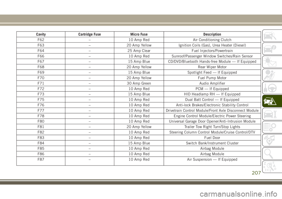
Cavity Cartridge Fuse Micro Fuse Description
F62 – 10 Amp Red Air Conditioning Clutch
F63 – 20 Amp Yellow Ignition Coils (Gas), Urea Heater (Diesel)
F64 – 25 Amp Clear Fuel Injectors/Powertrain
F66 – 10 Amp Red Sunroof/Passenger Window Switches/Rain Sensor
F67 – 15 Amp Blue CD/DVD/Bluetooth Hands-free Module — If Equipped
F68 – 20 Amp Yellow Rear Wiper Motor
F69 – 15 Amp Blue Spotlight Feed — If Equipped
F70 – 20 Amp Yellow Fuel Pump Motor
F71 – 30 Amp Green Audio Amplifier
F72 – 10 Amp Red PCM — If Equipped
F73 – 15 Amp Blue HID Headlamp RH — If Equipped
F75 – 10 Amp Red Dual Batt Control — If Equipped
F76 – 10 Amp Red Anti-lock Brakes/Electronic Stability Control
F77 – 10 Amp Red Drivetrain Control Module/Front Axle Disconnect Module
F78 – 10 Amp Red Engine Control Module/Electric Power Steering
F80 – 10 Amp Red Universal Garage Door Opener/Anti-Intrusion Module
F81 – 20 Amp Yellow Trailer Tow Right Turn/Stop Lights
F82 – 10 Amp Red Steering Column Control Module/Cruise Control/DTV
F83 – 10 Amp Red Fuel Door
F84 – 15 Amp Blue Switch Bank/Instrument Cluster
F85 – 10 Amp Red Airbag Module
F86 – 10 Amp Red Airbag Module
F87 – 10 Amp Red Air Suspension — If Equipped
207