ESP JEEP GRAND CHEROKEE 2021 Owner handbook (in English)
[x] Cancel search | Manufacturer: JEEP, Model Year: 2021, Model line: GRAND CHEROKEE, Model: JEEP GRAND CHEROKEE 2021Pages: 378, PDF Size: 6.88 MB
Page 106 of 378
(193 kPa), a temperature drop to 20°F (-7°C)
will decrease the tire pressure to approxi-
mately 24 psi (165 kPa). This tire pressure is
sufficiently low enough to turn on the TPMS
Warning Light. Driving the vehicle may cause
the tire pressure to rise to approximately
28 psi (193 kPa), but the TPMS Warning
Light will still be on. In this situation, the
TPMS Warning Light will turn off only after
the tires have been inflated to the vehicle’s
recommended cold tire pressure value.
CAUTION!
• The TPMS has been optimized for the
original equipment tires and wheels.
TPMS pressures and warnings have
been established for the tire size
equipped on your vehicle. Undesirable
system operation or sensor damage may
result when using replacement equip-
ment that is not of the same size, type,
and/or style. The TPM sensor is not de-
signed for use on aftermarket wheels
and may contribute to a poor overall
system performance or sensor damage.
Customers are encouraged to use OEM
CAUTION!
wheels to assure proper TPM feature
operation.
• Using aftermarket tire sealants may
cause the Tire Pressure Monitoring Sys-
tem (TPMS) sensor to become inoper-
able. After using an aftermarket tire
sealant it is recommended that you take
your vehicle to an authorized dealership
to have your sensor function checked.
• After inspecting or adjusting the tire
pressure, always reinstall the valve stem
cap. This will prevent moisture and dirt
from entering the valve stem, which
could damage the Tire Pressure Monitor-
ing Sensor.
NOTE:
• The TPMS is not intended to replace nor-
mal tire care and maintenance, or to pro-
vide warning of a tire failure or condition.
• The TPMS should not be used as a tire
pressure gauge while adjusting your tire
pressure.• Driving on a significantly under-inflated tire
causes the tire to overheat and can lead to
tire failure. Under-inflation also reduces
fuel efficiency and tire tread life, and may
affect the vehicle’s handling and stopping
ability.
• The TPMS is not a substitute for proper tire
maintenance, and it is the driver’s respon-
sibility to maintain correct tire pressure
using an accurate tire gauge, even if under-
inflation has not reached the level to trigger
illumination of the TPMS Warning Light.
• Seasonal temperature changes will affect
tire pressure, and the TPMS will monitor
the actual tire pressure in the tire.
• The system only warns the tire pressure is
low: it is not able to inflate them.
The Tire Pressure Monitor System (TPMS)
uses wireless technology with wheel rim-
mounted electronic sensors to monitor tire
pressure levels. Sensors, mounted to each
wheel as part of the valve stem, transmit tire
pressure readings to the Receiver Module.
SAFETY
104
Page 124 of 378
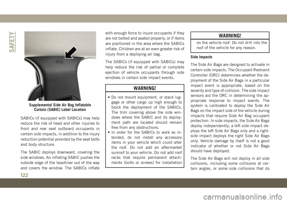
SABICs (if equipped with SABICs) may help
reduce the risk of head and other injuries to
front and rear seat outboard occupants in
certain side impacts, in addition to the injury
reduction potential provided by the seat belts
and body structure.
The SABIC deploys downward, covering the
side windows. An inflating SABIC pushes the
outside edge of the headliner out of the way
and covers the window. The SABICs inflatewith enough force to injure occupants if they
are not belted and seated properly, or if items
are positioned in the area where the SABICs
inflate. Children are at an even greater risk of
injury from a deploying air bag.
The SABICs (if equipped with SABICs) may
help reduce the risk of partial or complete
ejection of vehicle occupants through side
windows in certain side impact events.
WARNING!
• Do not mount equipment, or stack lug-
gage or other cargo up high enough to
block the deployment of the SABICs.
The trim covering above the side win-
dows where the SABIC and its deploy-
ment path are located should remain
free from any obstructions.
• In order for the SABICs to work as in-
tended, do not install any accessory
items in your vehicle which could alter
the roof. Do not add an aftermarket
sunroof to your vehicle. Do not add roof
racks that require permanent attach-
ments (bolts or screws) for installation
WARNING!
on the vehicle roof. Do not drill into the
roof of the vehicle for any reason.
Side Impacts
The Side Air Bags are designed to activate in
certain side impacts. The Occupant Restraint
Controller (ORC) determines whether the de-
ployment of the Side Air Bags in a particular
impact event is appropriate, based on the
severity and type of collision. The side impact
sensors aid the ORC in determining the ap-
propriate response to impact events. The
system is calibrated to deploy the Side Air
Bags on the impact side of the vehicle during
impacts that require Side Air Bag occupant
protection. In side impacts, the Side Air Bags
deploy independently; a left side impact de-
ploys the left Side Air Bags only and a right-
side impact deploys the right Side Air Bags
only. Vehicle damage by itself is not a good
indicator of whether or not Side Air Bags
should have deployed.
The Side Air Bags will not deploy in all side
collisions, including some collisions at cer-
tain angles, or some side collisions that do
Supplemental Side Air Bag Inflatable
Curtain (SABIC) Label Location
SAFETY
122
Page 127 of 378
Enhanced Accident Response System
In the event of an impact, if the communica-
tion network remains intact, and the power
remains intact, depending on the nature of
the event, the ORC will determine whether to
have the Enhanced Accident Response Sys-
tem perform the following functions:
• Cut off fuel to the engine (If Equipped)
• Cut off battery power to the electric motor
(If Equipped)
• Flash hazard lights as long as the battery
has power
• Turn on the interior lights, which remain on
as long as the battery has power or for 15
minutes from the intervention of the En-
hanced Accident Response System.
• Unlock the power door locks.
Your vehicle may also be designed to perform
any of these other functions in response to
the Enhanced Accident Response System:
• Turn off the Fuel Filter Heater, Turn off the
HVAC Blower Motor, Close the HVAC Circu-
lation Door• Cut off battery power to the:
– Engine
– Electric Motor (if equipped)
– Electric power steering
– Brake booster
– Electric park brake
– Automatic transmission gear selector
– Horn
– Front wiper
– Headlamp washer pump
NOTE:
After an accident, remember to cycle the
ignition to the STOP (OFF/LOCK) position
and remove the key from the ignition switch
to avoid draining the battery. Carefully check
the vehicle for fuel leaks in the engine com-
partment and on the ground near the engine
compartment and fuel tank before resetting
the system and starting the engine. If there
are no fuel leaks or damage to the vehicle
electrical devices (e.g. headlights) after an
accident, reset the system by following the
procedure described below. If you have any
doubt, contact an authorized dealer.
Enhanced Accident Response System Reset
Procedure
In order to reset the Enhanced Accident Re-
sponse System functions after an event, the
ignition switch must be changed from igni-
tion START or ON/RUN to ignition OFF. Care-
fully check the vehicle for fuel leaks in the
engine compartment and on the ground near
the engine compartment and fuel tank before
resetting the system and starting the engine.
Maintaining Your Air Bag System
WARNING!
• Modifications to any part of the air bag
system could cause it to fail when you
need it. You could be injured if the air
bag system is not there to protect you.
Do not modify the components or wiring,
including adding any kind of badges or
stickers to the steering wheel hub trim
cover or the upper passenger side of the
instrument panel. Do not modify the
front bumper, vehicle body structure, or
add aftermarket side steps or running
boards.
125
Page 155 of 378
While cruising, brief full-throttle acceleration
within the limits of local traffic laws contrib-
utes to a good break-in. However, wide-open
throttle acceleration in low gear can be det-
rimental and should be avoided.
The engine oil, transmission fluid, and axle
lubricant installed at the factory is high-
quality and energy-conserving. Oil, fluid, and
lubricant changes should be consistent with
anticipated climate and conditions under
which vehicle operations will occur. For the
recommended viscosity and quality grades,
refer to “Fluids And Lubricants” in "Techni-
cal Specifications”.
CAUTION!
Never use Non-Detergent Oil or Straight
Mineral Oil in the engine or damage may
result.NOTE:
A new engine may consume some oil during
its first few thousand miles (kilometers) of
operation. This should be considered a nor-
mal part of the break-in and not interpreted
as an indication of difficulty. Please check
your oil level with the engine oil indicator
often during the break in period. Add oil as
required.
Diesel Engine
The diesel engine does not require a break-in
period due to its construction. Normal opera-
tion is allowed, providing the following rec-
ommendations are followed:
• Warm up the engine before placing it under
load.
• Do not operate the engine at idle for pro-
longed periods.
• Use the appropriate transmission gear to
prevent engine lugging.
• Observe vehicle oil pressure and tempera-
ture indicators.
• Check the coolant and oil levels frequently.• Vary throttle position at highway speeds
when carrying or towing significant weight.
NOTE:
Light duty operation such as light trailer tow-
ing or no load operation will extend the time
before the engine is at full efficiency. Re-
duced fuel economy and power may be seen
at this time.
The engine oil installed in the engine at the
factory is a high-quality energy conserving
type lubricant. Oil changes should be consis-
tent with anticipated climate conditions un-
der which vehicle operations will occur. The
recommended viscosity and quality grades
are shown under “Fluids And Lubricants” in
"Technical Specifications” in this manual.
NON-DETERGENT OR STRAIGHT MINERAL
OILS MUST NEVER BE USED.
SRT Engines
The following tips will be helpful in obtaining
optimum performance and maximum dura-
bility for your new SRT Vehicle.
Despite modern technology and World Class
manufacturing methods, the moving parts of
the vehicle must still wear in with each other.
153
Page 161 of 378
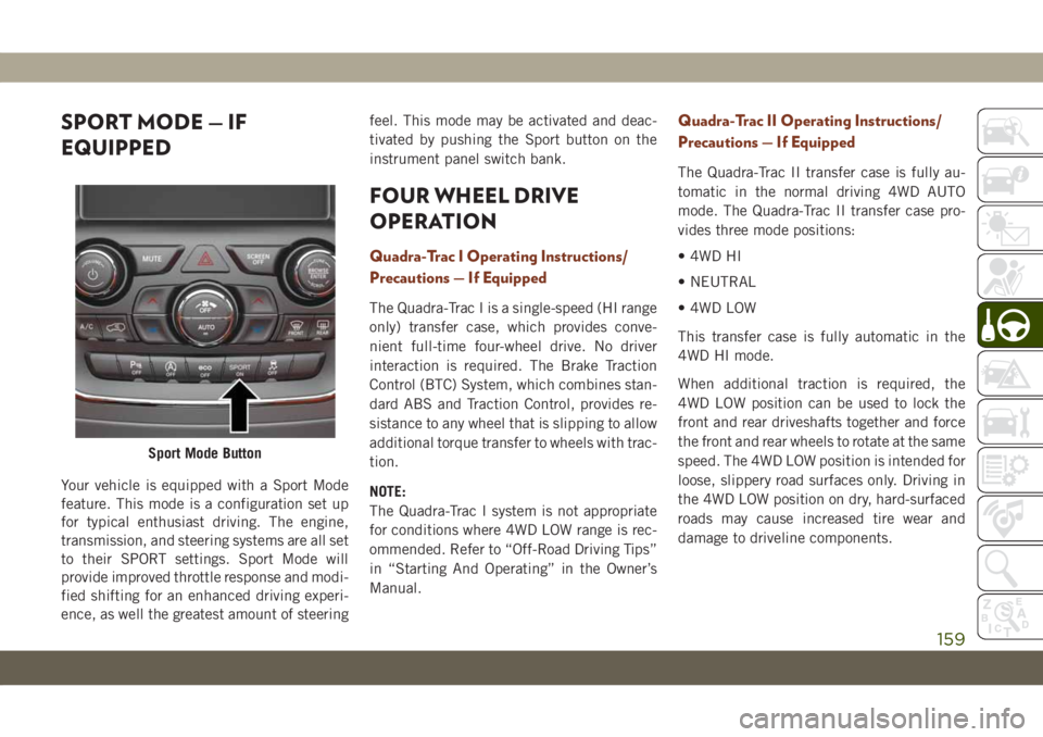
SPORT MODE — IF
EQUIPPED
Your vehicle is equipped with a Sport Mode
feature. This mode is a configuration set up
for typical enthusiast driving. The engine,
transmission, and steering systems are all set
to their SPORT settings. Sport Mode will
provide improved throttle response and modi-
fied shifting for an enhanced driving experi-
ence, as well the greatest amount of steeringfeel. This mode may be activated and deac-
tivated by pushing the Sport button on the
instrument panel switch bank.
FOUR WHEEL DRIVE
OPERATION
Quadra-Trac I Operating Instructions/
Precautions — If Equipped
The Quadra-Trac I is a single-speed (HI range
only) transfer case, which provides conve-
nient full-time four-wheel drive. No driver
interaction is required. The Brake Traction
Control (BTC) System, which combines stan-
dard ABS and Traction Control, provides re-
sistance to any wheel that is slipping to allow
additional torque transfer to wheels with trac-
tion.
NOTE:
The Quadra-Trac I system is not appropriate
for conditions where 4WD LOW range is rec-
ommended. Refer to “Off-Road Driving Tips”
in “Starting And Operating” in the Owner’s
Manual.
Quadra-Trac II Operating Instructions/
Precautions — If Equipped
The Quadra-Trac II transfer case is fully au-
tomatic in the normal driving 4WD AUTO
mode. The Quadra-Trac II transfer case pro-
vides three mode positions:
• 4WD HI
• NEUTRAL
• 4WD LOW
This transfer case is fully automatic in the
4WD HI mode.
When additional traction is required, the
4WD LOW position can be used to lock the
front and rear driveshafts together and force
the front and rear wheels to rotate at the same
speed. The 4WD LOW position is intended for
loose, slippery road surfaces only. Driving in
the 4WD LOW position on dry, hard-surfaced
roads may cause increased tire wear and
damage to driveline components.
Sport Mode Button
159
Page 181 of 378
WARNING!
• Drivers must be careful when backing up
even when using ParkSense. Always
check carefully behind your vehicle, look
behind you, and be sure to check for
pedestrians, animals, other vehicles, ob-
structions, and blind spots before back-
ing up. You are responsible for safety
and must continue to pay attention to
your surroundings. Failure to do so can
result in serious injury or death.
• Before using ParkSense, it is strongly
recommended that the ball mount and
hitch ball assembly is disconnected
from the vehicle when the vehicle is not
used for towing. Failure to do so can
result in injury or damage to vehicles or
obstacles because the hitch ball will be
much closer to the obstacle than the rear
fascia when the loudspeaker sounds the
continuous tone. Also, the sensors could
detect the ball mount and hitch ball
assembly, depending on its size and
shape, giving a false indication that an
obstacle is behind the vehicle.
CAUTION!
• ParkSense is only a parking aid and it is
unable to recognize every obstacle, in-
cluding small obstacles. Parking curbs
might be temporarily detected or not
detected at all. Obstacles located above
or below the sensors will not be detected
when they are in close proximity.
• The vehicle must be driven slowly when
using ParkSense in order to be able to
stop in time when an obstacle is de-
tected. It is recommended that the
driver looks over his/her shoulder when
using ParkSense.
PARKSENSE FRONT AND
REAR PARK ASSIST — IF
EQUIPPED
The ParkSense Park Assist system provides
visual and audible indications of the distance
between the rear and/or front fascia and a
detected obstacle when backing up or moving
forward, e.g. during a parking maneuver. If
your vehicle is equipped with an automatictransmission, the vehicle brakes may be au-
tomatically applied and released when per-
forming a reverse parking maneuver if the
system detects a possible collision with an
obstacle.
Refer to “ParkSense System Usage Precau-
tions” in “Starting And Operating” in your
Owner’s Manual for limitations of this system
and recommendations.
ParkSense will retain the last system state
(enabled or disabled) from the last ignition
cycle when the ignition is changed to the
ON/RUN position.
ParkSense Sensors
The four ParkSense sensors (or six, if
equipped with Active Park Assist), located in
the rear fascia/bumper, monitor the area be-
hind the vehicle that is within the sensors’
field of view. The sensors can detect ob-
stacles from approximately 12 inches
(30 cm) up to 79 inches (200 cm) from the
rear fascia/bumper in the horizontal direc-
tion, depending on the location, type and
orientation of the obstacle.
179
Page 183 of 378
NOTE:
• The driver is always responsible for control-
ling the vehicle, responsible for any sur-
rounding objects, and must intervene as
required.
• The system is provided to assist the driver
and not to substitute the driver.
• During a semi-automatic maneuver, if the
driver touches the steering wheel after be-
ing instructed to remove their hands from
the steering wheel, the system will cancel,
and the driver will be required to manually
complete the parking maneuver.
• The system may not work in all conditions
(e.g. environmental conditions such as
heavy rain, snow, etc., or if searching for a
parking space that has surfaces that will
absorb the ultrasonic sensor waves).
•N
ew vehicles from the dealership must have
at least 30 miles (48 km) accumulated be-
fore the ParkSense Active Park Assist system
is fully calibrated and performs accurately.
This is due to the system’s dynamic vehicle
calibration to improve the performance of the
feature. The system will also continuouslyperform the dynamic vehicle calibration to
account for differences such as over or under
inflated tires and new tires.
Enabling And Disabling The ParkSense
Active Park Assist System
The ParkSense Active Park As-
sist system can be enabled and
disabled with the ParkSense Ac-
tive Park Assist switch, located
on the switch panel below the
Uconnect display.
To enable the ParkSense Active Park Assist
system, push the ParkSense Active Park As-
sist switch once (LED turns on).
To disable the ParkSense Active Park Assist
system, push the ParkSense Active Park As-
sist switch again (LED turns off).
When the ParkSense Active Park Assist sys-
tem is enabled the “Active ParkSense
Searching - Push OK to Switch to Perpen-
dicular” message will appear in the instru-
ment cluster display. You may switch to per-
pendicular parking if you desire. Push the OKbutton on the left side steering wheel switch
to change your parking space setting. You
may switch back to parallel parking if you
desire.
When searching for a parking space, use the
turn signal indicator to select which side of
the vehicle you want to perform the parking
maneuver.
NOTE:
If the turn signal is not activated, the
ParkSense Active Park Assist system will au-
tomatically search for a parking space on the
passenger's side of the vehicle.
Refer to your Owner's Manual for further
information.
LANESENSE — IF EQUIPPED
LaneSense Operation
The LaneSense system is operational at
speeds above 37 mph (60 km/h) and below
112 mph (180 km/h). The LaneSense system
uses a forward looking camera to detect lane
markings and measure vehicle position
within the lane boundaries.
181
Page 187 of 378
WARNING!
Drivers must be careful when backing up
even when using the ParkView Rear Back
Up Camera. Always check carefully behind
your vehicle, and be sure to check for
pedestrians, animals, other vehicles, ob-
structions, or blind spots before backing
up. You are responsible for the safety of
your surroundings and must continue to
pay attention while backing up. Failure to
do so can result in serious injury or death.
CAUTION!
• To avoid vehicle damage, ParkView
should only be used as a parking aid.
The ParkView camera is unable to view
every obstacle or object in your drive
path.
• To avoid vehicle damage, the vehicle
must be driven slowly when using
ParkView to be able to stop in time when
an obstacle is seen. It is recommended
that the driver look frequently over his/
her shoulder when using ParkView.NOTE:
If snow, ice, mud, or any foreign substance
builds up on the camera lens, clean the lens,
rinse with water, and dry with a soft cloth. Do
not cover the lens.
Rear Camera — Viewing At Speed
When the vehicle is in park, neutral or drive,
the Rear View Camera can be activated with
the “Rear View Camera” button in the Con-
trols menu. This feature allows the customer
to monitor the area directly behind the ve-
hicle (or trailer, if equipped) for up to ten
seconds while at speed. If the vehicle speed
remains below 8 mph (13 km/h), the Rear
View Camera image will be displayed con-
tinuously until deactivated via the “X” button
on the touchscreen.
REFUELING THE VEHICLE —
GASOLINE ENGINE
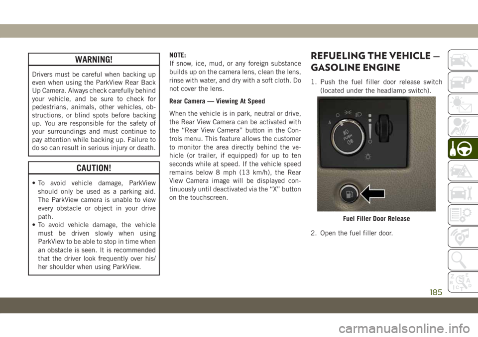
1. Push the fuel filler door release switch
(located under the headlamp switch).
2. Open the fuel filler door.
Fuel Filler Door Release
185
Page 212 of 378
FUSES
WARNING!
•When replacing a blown fuse, always use
an appropriate replacement fuse with the
same amp rating as the original fuse. Never
replace a fuse with another fuse of higher
amp rating. Never replace a blown fuse
with metal wires or any other material. Do
not place a fuse inside a circuit breaker
cavity or vice versa. Failure to use proper
fuses may result in serious personal injury,
fire and/or property damage.
•Before replacing a fuse, make sure that the
ignition is off and that all the other services
are switched off and/or disengaged.
•If the replaced fuse blows again, contact
an authorized dealer.
•If a general protection fuse for safety sys-
tems (air bag system, braking system),
power unit systems (engine system, trans-
mission system) or steering system blows,
contact an authorized dealer.
CAUTION!
If it is necessary to wash the engine com-
partment, take care not to directly hit the
fuse box, and the windshield wiper motors
with water.
General Information
The fuses protect electrical systems against
excessive current.
When a device does not work, you must check
the fuse element inside the blade fuse for a
break/melt.
Also, please be aware that when using power
outlets for extended periods of time with the
engine off may result in vehicle battery dis-
charge.
Underhood Fuses
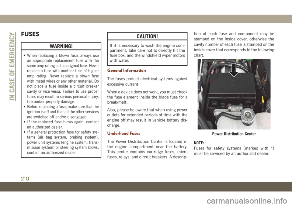
The Power Distribution Center is located in
the engine compartment near the battery.
This center contains cartridge fuses, micro
fuses, relays, and circuit breakers. A descrip-tion of each fuse and component may be
stamped on the inside cover, otherwise the
cavity number of each fuse is stamped on the
inside cover that corresponds to the following
chart.
NOTE:
Fuses for safety systems (marked with *)
must be serviced by an authorized dealer.
Power Distribution Center
IN CASE OF EMERGENCY
210
Page 237 of 378
WARNING!
movements. Do not start the engine
while towing the car. Before tightening
the ring, clean the threaded housing
thoroughly. Make sure that the ring is
fully screwed into the housing before
towing the car.
Front Tow Eye Installation
The front tow eye receptacle is located be-
hind a door on the front bumper fascia.
To install the tow eye, open the door using the
vehicle key or a small screwdriver, and thread
the tow eye into the receptacle.
Insert the flat end of the jack handle through
the tow eye and tighten, refer to “Jacking And
Tire Changing” in this section for further
information. The tow eye must be fully seated
to the attaching bracket through the lower
front fascia. If the tow eye is not fully seated
to the attaching bracket, the vehicle should
not be moved.
Emergency Tow Hooks — If Equipped
If your vehicle is equipped with tow hooks,
there will be one in the rear and two mounted
on the front of the vehicle. The rear hook will
be located on the driver's side of the vehicle.
NOTE:
For off-road recovery, it is recommended to
use both of the front tow hooks to minimize
the risk of damage to the vehicle.
WARNING!
• Do not use a chain for freeing a stuck
vehicle. Chains may break, causing seri-
ous injury or death.
• Stand clear of vehicles when pulling
with tow hooks. Tow straps may become
disengaged, causing serious injury.
CAUTION!
Tow hooks are for emergency use only, to
rescue a vehicle stranded off road. Do not
use tow hooks for tow truck hookup or
highway towing. You could damage your
vehicle.
ENHANCED ACCIDENT
RESPONSE SYSTEM (EARS)
This vehicle is equipped with an Enhanced
Accident Response System.
Please refer to “Occupant Restraint Sys-
tems” in “Safety” for further information on
the Enhanced Accident Response System
(EARS) function.
EVENT DATA RECORDER
(EDR)
This vehicle is equipped with an Event Data
Recorder (EDR). The main purpose of an EDR
is to record data that will assist in under-
standing how a vehicle’s systems performed
under certain crash or near crash-like situa-
tions, such as an air bag deployment or hit-
ting a road obstacle.
Please refer to “Occupant Restraint Sys-
tems” in “Safety” for further information on
the Event Data Recorder (EDR).
235