ignition JEEP GRAND CHEROKEE 2021 Owner handbook (in English)
[x] Cancel search | Manufacturer: JEEP, Model Year: 2021, Model line: GRAND CHEROKEE, Model: JEEP GRAND CHEROKEE 2021Pages: 378, PDF Size: 6.88 MB
Page 163 of 378
Shifting Procedures
4WD HI To 4WD LOW
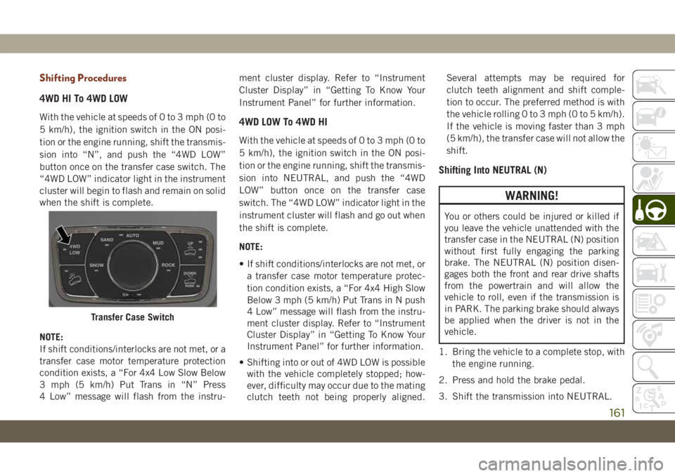
With the vehicle at speeds of 0 to 3 mph (0 to
5 km/h), the ignition switch in the ON posi-
tion or the engine running, shift the transmis-
sion into “N”, and push the “4WD LOW”
button once on the transfer case switch. The
“4WD LOW” indicator light in the instrument
cluster will begin to flash and remain on solid
when the shift is complete.
NOTE:
If shift conditions/interlocks are not met, or a
transfer case motor temperature protection
condition exists, a “For 4x4 Low Slow Below
3 mph (5 km/h) Put Trans in “N” Press
4 Low” message will flash from the instru-ment cluster display. Refer to “Instrument
Cluster Display” in “Getting To Know Your
Instrument Panel” for further information.4WD LOW To 4WD HI
With the vehicle at speeds of 0 to 3 mph (0 to
5 km/h), the ignition switch in the ON posi-
tion or the engine running, shift the transmis-
sion into NEUTRAL, and push the “4WD
LOW” button once on the transfer case
switch. The “4WD LOW” indicator light in the
instrument cluster will flash and go out when
the shift is complete.
NOTE:
• If shift conditions/interlocks are not met, or
a transfer case motor temperature protec-
tion condition exists, a “For 4x4 High Slow
Below 3 mph (5 km/h) Put Trans in N push
4 Low” message will flash from the instru-
ment cluster display. Refer to “Instrument
Cluster Display” in “Getting To Know Your
Instrument Panel” for further information.
• Shifting into or out of 4WD LOW is possible
with the vehicle completely stopped; how-
ever, difficulty may occur due to the mating
clutch teeth not being properly aligned.Several attempts may be required for
clutch teeth alignment and shift comple-
tion to occur. The preferred method is with
the vehicle rolling 0 to 3 mph (0 to 5 km/h).
If the vehicle is moving faster than 3 mph
(5 km/h), the transfer case will not allow the
shift.
Shifting Into NEUTRAL (N)
WARNING!
You or others could be injured or killed if
you leave the vehicle unattended with the
transfer case in the NEUTRAL (N) position
without first fully engaging the parking
brake. The NEUTRAL (N) position disen-
gages both the front and rear drive shafts
from the powertrain and will allow the
vehicle to roll, even if the transmission is
in PARK. The parking brake should always
be applied when the driver is not in the
vehicle.
1. Bring the vehicle to a complete stop, with
the engine running.
2. Press and hold the brake pedal.
3. Shift the transmission into NEUTRAL.
Transfer Case Switch
161
Page 164 of 378
4. If vehicle is equipped with Quadra-Lift air
suspension, ensure the vehicle is set to
Normal Ride Height.
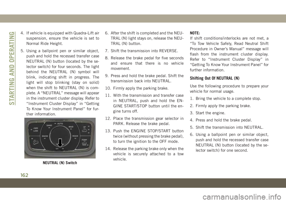
5. Using a ballpoint pen or similar object,
push and hold the recessed transfer case
NEUTRAL (N) button (located by the se-
lector switch) for four seconds. The light
behind the NEUTRAL (N) symbol will
blink, indicating shift in progress. The
light will stop blinking (stay on solid)
when the shift to NEUTRAL (N) is com-
plete. A “NEUTRAL” message will appear
in the instrument cluster display. Refer to
“Instrument Cluster Display” in “Getting
To Know Your Instrument Panel” for fur-
ther information.6. After the shift is completed and the NEU-
TRAL (N) light stays on, release the NEU-
TRAL (N) button.
7. Shift the transmission into REVERSE.
8. Release the brake pedal for five seconds
and ensure that there is no vehicle
movement.
9. Press and hold the brake pedal. Shift the
transmission back into NEUTRAL.
10. Firmly apply the parking brake.
11. With the transmission and transfer case
in NEUTRAL, push and hold the EN-
GINE START/STOP button until the en-
gine turns off.
12. Place the transmission gear selector in
PARK. Release the brake pedal.
13. Push the ENGINE STOP/START button
twice (without pressing the brake pedal),
to turn the ignition to the OFF mode.
14. Release the parking brake only when the
vehicle is securely attached to a tow
vehicle.NOTE:
If shift conditions/interlocks are not met, a
“To Tow Vehicle Safely, Read Neutral Shift
Procedure in Owner’s Manual” message will
flash from the instrument cluster display.
Refer to “Instrument Cluster Display” in
“Getting To Know Your Instrument Panel” for
further information.
Shifting Out Of NEUTRAL (N)
Use the following procedure to prepare your
vehicle for normal usage.
1. Bring the vehicle to a complete stop.
2. Firmly apply the parking brake.
3. Start the engine.
4. Press and hold the brake pedal.
5. Shift the transmission into NEUTRAL.
6. Using a ballpoint pen or similar object,
push and hold the recessed transfer case
NEUTRAL (N) button (located by the se-
lector switch) for one second.
NEUTRAL (N) Switch
STARTING AND OPERATING
162
Page 166 of 378
•Off-Road 1 (OR1) (Raises the vehicle approxi-
mately 1.1 inches (28 mm))– This is the
primary position for all off-road driving until
OR2 is needed. A smoother and more com-
fortable ride will result. Push the “UP”
button once from the NRH position while
the vehicle speed is below 38 mph
(61 km/h). When in the OR1 position, if the
vehicle speed remains between 40 mph
(64 km/h) and 50 mph (80 km/h) for
greater than 20 seconds or if the vehicle
speed exceeds 50 mph (80 km/h), the
vehicle will be automatically lowered to
NRH.
•Off-Road 2 (OR2) (Raises the vehicle approxi-
mately 2.2 inches (55 mm))– This position is
intended for off-roading use only where
maximum ground clearance is required. To
enter OR2, push the “UP” button twice
from the NRH position or once from the
OR1 position while vehicle speed is below
20 mph (32 km/h). While in OR2, if the
vehicle speed exceeds 25 mph (40 km/h)
the vehicle height will be automatically
lowered to OR1.•Aero Mode (Lowers the vehicle approximately
0.6 inches (15 mm))– This position provides
improved aerodynamics by lowering the ve-
hicle. The vehicle will automatically enter
Aero Mode when the vehicle speed remains
between 52 mph (83 km/h) and 56 mph
(90 km/h) for greater than 20 seconds or if
the vehicle speed exceeds 56 mph
(90 km/h). The vehicle will return to NRH
from Aero Mode if the vehicle speed re-
mains between 20 mph (32 km/h) and
25 mph (40 km/h) for greater than 20 sec-
onds or if the vehicle speed falls below
20 mph (32 km/h). The vehicle will enter
Aero Mode, regardless of vehicle speed if
the vehicle is in “SPORT” mode.
•Entry/Exit Mode (Lowers the vehicle approxi-
mately 1.6 inches (40 mm)– This position
lowers the vehicle for easier passenger en-
try and exit as well as lowering the rear of
the vehicle for easier loading and unloading
of cargo. To enter Entry/Exit Mode, push the
“DOWN” button once from (NRH) while the
vehicle speed is below 25 mph (40 km/h).
Once the vehicle speed goes below 15 mph
(24 km/h) the vehicle height will begin to
lower. If the vehicle speed remains between15 mph (24 km/h) and 25 mph (40 km/h)
for greater than 60 seconds, or the vehicle
speed exceeds 25 mph (40 km/h) the
Entry/Exit Mode change will be cancelled.
To exit Entry/Exit Mode, press the “Up”
button once while in Entry/Exit Mode or
drive the vehicle over 15 mph (24 km/h).
NOTE:
Automatic lowering of the vehicle into Entry/
Exit Mode can be enabled through the
Uconnect Touch-Screen Radio. If this feature
is enabled, the vehicle will only lower if the
gear selector is in "PARK", the terrain switch
is in "AUTO", the transfer-case is in "AUTO”
and the vehicle level should be either in
Normal or Aero Mode. The Vehicle will not
automatically lower if the air suspension level
is in Off Rd 2 or Off Rd 1. If the vehicle is
equipped with Intrusion Theft Module (ITM),
the lowering will be suppressed when the
ignition is switched OFF and the door is open
to prevent setting the alarm off.
The Selec-Terrain switch will automatically
change the vehicle to the proper height based
on the position of the Selec-Terrain switch.
The height can be changed from the default
STARTING AND OPERATING
164
Page 171 of 378
Refer to “SRT Drive Modes” in the “Multime-
dia” section in your Owner’s Manual for fur-
ther information.
Selec-Track consists of the following posi-
tions:
•Sport– Dry weather, on-road calibration.
Performance based tuning that provides a
rear wheel drive feel but with improved
handling and acceleration over a two-wheel
drive vehicle. This feature will reset to
AUTO on an ignition cycle.
•Snow– Tuning set for additional stability in
inclement weather. Use on and off road on
loose traction surfaces such as snow. This
feature will reset to AUTO upon an ignition
cycle.
•Auto– Fully automatic full time four-wheel
drive operation can be used on and off road.
Balances traction with seamless steering
feel to provide improved handling and ac-
celeration over two-wheel drive vehicles.•Track– Track road calibration for use on
high traction surfaces. Driveline is maxi-
mized for traction. Some binding may be
felt on less forgiving surfaces. This feature
will reset to AUTO on an ignition cycle.
•To w– Use this mode for towing and hauling
heavy loads. Vehicle suspension will go to
sport mode. Trailer sway control is enabled
in the ESC system. This feature will reset to
AUTO upon an ignition cycle.
Custom
This mode allows the driver to create a cus-
tom vehicle configuration that is saved for
quick selection of favorite settings. The sys-
tem will return to AUTO mode when the
ignition switch is cycled from RUN to OFF to
RUN, if this mode is selected. While in Cus-
tom Mode the Stability, Transmission, Steer-
ing, Suspension, all-wheel drive set up, and
Paddle shifter settings may be configured
through the custom mode set-up.
NOTE:
Refer to “SRT Drive Modes” in the “Multime-
dia” section in your Owner’s Manual for fur-
ther information.
Active Damping System
This vehicle is equipped with an electronic
controlled damping system. This system re-
duces body roll and pitch in many driving
situations including cornering, acceleration
and braking. There are 3 modes:
•Street Mode(Available in terrain positions
AUTO, SNOW and CUSTOM.) — Used dur-
ing highway speeds where a touring sus-
pension feel is desired.
•Sport Mode(Available in terrain positions
AUTO, SPORT, CUSTOM and TOW.) — Pro-
vides a firm suspension for better handling.
•Track Mode(Available in terrain positions
AUTO, TRACK and CUSTOM.) — Provides
a full firm suspension for an aggressive
track experience.
Refer to “SRT Drive Modes” in the “Multime-
dia” section in your Owner’s Manual for fur-
ther information.
169
Page 179 of 378
downhill. This is normal operation and nec-
essary to maintain set speed. When driving
up hill and down hill, the ACC system will
cancel if the braking temperature exceeds
normal range (overheated).
Setting The Following Distance In ACC
The specified following distance for ACC can
be set by varying the distance setting be-
tween four bars (longest), three bars (long),
two bars (medium) and one bar (short). Using
this distance setting and the vehicle speed,
ACC calculates and sets the distance to the
vehicle ahead. This distance setting displays
in the instrument cluster display.
To increase the distance setting, push the
Distance Setting — Increase button and re-
lease. Each time the button is pushed, the
distance setting increases by one bar (lon-
ger).
To decrease the distance setting, push the
Distance Setting — Decrease button and re-
lease. Each time the button is pushed, the
distance setting decreases by one bar
(shorter).
PARKSENSE REAR PARK
ASSIST — IF EQUIPPED
The ParkSense Rear Park Assist system pro-
vides visual and audible indications of the
distance between the rear fascia and a de-
tected obstacle when backing up, e.g. during
a parking maneuver. If your vehicle is
equipped with an automatic transmission,
the vehicle brakes may be automatically ap-
plied and released when performing a reverse
parking maneuver if the system detects a
possible collision with an obstacle.
Refer to “ParkSense System Usage Precau-
tions” in this section for limitations of this
system and recommendations.
ParkSense will retain the last system state
(enabled or disabled) from the last ignition
cycle when the ignition is changed to the
ON/RUN position.
ParkSense Sensors
The four ParkSense sensors, located in the
rear fascia/bumper, monitor the area behind
the vehicle that is within the sensors’ field of
view. The sensors can detect obstacles from
approximately 12 inches (30 cm) up to
79 inches (200 cm) from the rear fascia/
bumper in the horizontal direction, depend-
ing on the location, type and orientation of
the obstacle.
ParkSense Warning Display
The ParkSense Warning screen will only be
displayed if Sound and Display is selected
from the Customer - Programmable Features
section of the Uconnect System.
Refer to "Uconnect Settings” in “Multime-
dia” in your Owner’s Manual for further infor-
mation.
The ParkSense Warning screen is located
within the instrument cluster display. It pro-
vides visual warnings to indicate the distance
between the rear fascia/bumper and the de-
tected obstacle.
177
Page 180 of 378
Refer to “Instrument Cluster Display” in
“Getting To Know Your Instrument Panel” in
your Owner’s Manual for further information.
Enabling And Disabling ParkSense
ParkSense can be enabled and disabled with
the ParkSense switch.
When the ParkSense switch is
pushed to disable the system, the
instrument cluster will display the
“PARKSENSE OFF” message for
approximately five seconds. When the gear
selector is moved to REVERSE and the sys-
tem is disabled, the instrument cluster dis-
play will display the “PARKSENSE OFF”
message for as long as the vehicle is in
REVERSE.
Refer to “Instrument Cluster Display” in
“Getting To Know Your Instrument Panel” in
your Owner’s Manual for further information.
The ParkSense switch LED will be on when
ParkSense is disabled or requires service.
The ParkSense switch LED will be off when
the system is enabled. If the ParkSenseswitch is pushed, and the system requires
service, the ParkSense switch LED will blink
momentarily, and then the LED will be on.
ParkSense System Usage Precautions
NOTE:
• Ensure that the rear bumper is free of snow,
ice, mud, dirt and debris to keep the
ParkSense system operating properly.
• Jackhammers, large trucks, and other vi-
brations could affect the performance of
ParkSense.
• When you turn ParkSense off, the instru-
ment cluster will display “PARKSENSE
OFF.” Furthermore, once you turn
ParkSense off, it remains off until you turn
it on again, even if you cycle the ignition.
• When you move the gear selector to the
REVERSE position and ParkSense is
turned off, the instrument cluster display
will display “PARKSENSE OFF” message
for as long as the vehicle is in REVERSE.
• ParkSense, when on, will reduce the vol-
ume of the radio when it is sounding a tone.• Clean the ParkSense sensors regularly, tak-
ing care not to scratch or damage them.
The sensors must not be covered with ice,
snow, slush, mud, dirt or debris. Failure to
do so can result in the system not working
properly. The ParkSense system might not
detect an obstacle behind the fascia/
bumper, or it could provide a false indica-
tion that an obstacle is behind the fascia/
bumper.
• Use the ParkSense switch to turn the
ParkSense system off if objects such as
bicycle carriers, trailer hitches, etc. are
placed within 12 inches (30 cm) from the
rear fascia/bumper. Failure to do so can
result in the system misinterpreting a close
object as a sensor problem, causing the
“PARKSENSE UNAVAILABLE SERVICE
REQUIRED” message to be displayed in
the instrument cluster display.
• ParkSense should be disabled when the
liftgate is in the open position and the
vehicle is in REVERSE. An open liftgate
could provide a false indication that an
obstacle is behind the vehicle.
STARTING AND OPERATING
178
Page 181 of 378
WARNING!
• Drivers must be careful when backing up
even when using ParkSense. Always
check carefully behind your vehicle, look
behind you, and be sure to check for
pedestrians, animals, other vehicles, ob-
structions, and blind spots before back-
ing up. You are responsible for safety
and must continue to pay attention to
your surroundings. Failure to do so can
result in serious injury or death.
• Before using ParkSense, it is strongly
recommended that the ball mount and
hitch ball assembly is disconnected
from the vehicle when the vehicle is not
used for towing. Failure to do so can
result in injury or damage to vehicles or
obstacles because the hitch ball will be
much closer to the obstacle than the rear
fascia when the loudspeaker sounds the
continuous tone. Also, the sensors could
detect the ball mount and hitch ball
assembly, depending on its size and
shape, giving a false indication that an
obstacle is behind the vehicle.
CAUTION!
• ParkSense is only a parking aid and it is
unable to recognize every obstacle, in-
cluding small obstacles. Parking curbs
might be temporarily detected or not
detected at all. Obstacles located above
or below the sensors will not be detected
when they are in close proximity.
• The vehicle must be driven slowly when
using ParkSense in order to be able to
stop in time when an obstacle is de-
tected. It is recommended that the
driver looks over his/her shoulder when
using ParkSense.
PARKSENSE FRONT AND
REAR PARK ASSIST — IF
EQUIPPED
The ParkSense Park Assist system provides
visual and audible indications of the distance
between the rear and/or front fascia and a
detected obstacle when backing up or moving
forward, e.g. during a parking maneuver. If
your vehicle is equipped with an automatictransmission, the vehicle brakes may be au-
tomatically applied and released when per-
forming a reverse parking maneuver if the
system detects a possible collision with an
obstacle.
Refer to “ParkSense System Usage Precau-
tions” in “Starting And Operating” in your
Owner’s Manual for limitations of this system
and recommendations.
ParkSense will retain the last system state
(enabled or disabled) from the last ignition
cycle when the ignition is changed to the
ON/RUN position.
ParkSense Sensors
The four ParkSense sensors (or six, if
equipped with Active Park Assist), located in
the rear fascia/bumper, monitor the area be-
hind the vehicle that is within the sensors’
field of view. The sensors can detect ob-
stacles from approximately 12 inches
(30 cm) up to 79 inches (200 cm) from the
rear fascia/bumper in the horizontal direc-
tion, depending on the location, type and
orientation of the obstacle.
179
Page 184 of 378
When both lane markings are detected and
the driver unintentionally drifts out of the
lane (no turn signal applied), the LaneSense
system provides a haptic warning in the form
of torque applied to the steering wheel to
prompt the driver to remain within the lane
boundaries. If the driver continues to unin-
tentionally drift out of the lane, the Lane-
Sense system provides a visual warning
through the instrument cluster display to
prompt the driver to remain within the lane
boundaries.
The driver may manually override the haptic
warning by applying torque into the steering
wheel at any time.
When only a single lane marking is detected
and the driver unintentionally drifts across
the lane marking (no turn signal applied), the
LaneSense system provides visual warnings
through the instrument cluster display to
prompt the driver to remain within the lane.
When only a single lane marking is detected,
a haptic (torque) warning will not be
provided.NOTE:
When operating conditions have been met,
the LaneSense system will monitor if the
driver’s hands are on the steering wheel and
provides an audible warning to the driver
when the driver’s hands are not detected on
the steering wheel. The system will cancel if
the driver does not return their hands to the
wheel.
Turning LaneSense On Or Off
The default status of LaneSense is off. The
LED in LaneSense button will be illuminated
while the system is deactivated.
The LaneSense button is located
on the switch panel below the
Uconnect display.
To turn the LaneSense system
on, push the LaneSense button (LED turns
off). A “LaneSense On” message is shown in
the instrument cluster display.
To turn the LaneSense system off, push the
LaneSense button once (LED turns on).NOTE:
The LaneSense system will retain the last
system state on or off from the last ignition
cycle when the ignition is changed to the
ON/RUN position.
LaneSense Warning Message
The LaneSense system will indicate the cur-
rent lane drift condition through the instru-
ment cluster display.
Premium Instrument Cluster Display
When the LaneSense system is on; the lane
lines are gray when both of the lane bound-
aries have not been detected and the Lane-
Sense telltale
is solid white.
Left Lane Departure — Only Left Lane Detected
• When the LaneSense system is on, the
LaneSense telltale
is solid white when
only the left lane marking has been de-
tected and the system is ready to provide
visual warnings in the instrument cluster
display if an unintentional lane departure
occurs.
STARTING AND OPERATING
182
Page 186 of 378
PARKVIEW REAR BACK UP
CAMERA — IF EQUIPPED
The ParkView Rear Back Up Camera allows
you to see an on-screen image of the rear
surroundings of your vehicle whenever the
gear selector is put into REVERSE. The im-
age will be displayed on the Navigation/
Multimedia radio display screen along with a
caution note to “check entire surroundings”
across the top of the screen. After five sec-
onds this note will disappear. The ParkView
camera is located on the rear of the vehicle
above the rear license plate.
When the vehicle is shifted out of REVERSE
(with camera delay turned off), the rear cam-
era mode is exited and the navigation or
audio screen appears again.Manual Activation Of The Rear View Camera
1. Press the “Controls” button located on
the bottom of the Uconnect display.
2. Press the “Backup Camera” button to
turn the Rear View Camera system on.
NOTE:
The ParkView Rear Back Up Camera has
programmable modes of operation that may
be selected through the Uconnect System.
Refer to “Uconnect Settings” in “Multime-
dia” in your Owner’s Manual for further infor-
mation.
When the vehicle is shifted out of REVERSE
(with camera delay turned off), the rear cam-
era mode is exited and the previous screen
appears again. When the vehicle is shifted
out of REVERSE (with camera delay turnedon), the camera image will continue to be
displayed for up to ten seconds after shifting
out of REVERSE unless the vehicle speed
exceeds 8 mph (13 km/h), the vehicle is
shifted into PARK, the vehicle’s ignition is
cycled to the OFF position, or the user
presses image defeat [X] to exit out of the
camera video display.
When enabled, active guide lines are overlaid
on the image to illustrate the width of the
vehicle and its projected backup path based
on the steering wheel position. A dashed
center line overlay indicates the center of the
vehicle to assist with parking or aligning to a
hitch/receiver. Different colored zones indi-
cate the distance to the rear of the vehicle.
The following table shows the approximate
distances for each zone:
Zone Distance To The Rear Of The Vehicle
Red 0-1ft(0-30cm)
Yellow 1 ft - 6.5 ft (30 cm-2m)
Green 6.5 ft or greater (2 m or greater)
STARTING AND OPERATING
184
Page 193 of 378
NOTE:
When working with AdBlue®, it is important
to know that:
• Any containers or parts that come into con-
tact with AdBlue
®must be AdBlue®com-
patible (plastic or stainless steel). Copper,
brass, aluminum, iron or non-stainless
steel should be avoided as they are subject
to corrosion by AdBlue
®.
• If AdBlue
®is spilled, it should be wiped up
completely.
Adding AdBlue®
Preliminary Conditions
AdBlue
®freezes at temperatures lower than
12° F (-11° C). If the car stands for a long
time at this temperature refilling could be
difficult. For this reason, it is advised to park
the vehicle in a garage and/or heated environ-
ment and wait for the urea to return to liquid
state before topping up.Proceed as follows:
• Park the car on flat ground and stop the
engine by cycling the ignition to the OFF
position.
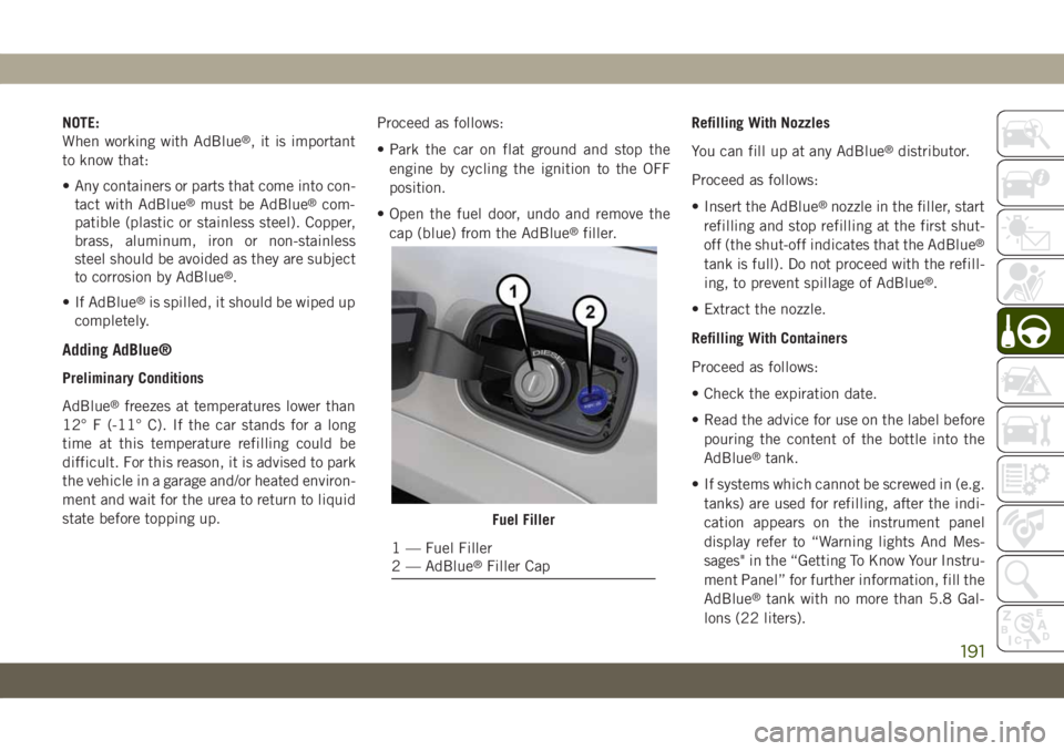
• Open the fuel door, undo and remove the
cap (blue) from the AdBlue
®filler.Refilling With Nozzles
You can fill up at any AdBlue
®distributor.
Proceed as follows:
• Insert the AdBlue
®nozzle in the filler, start
refilling and stop refilling at the first shut-
off (the shut-off indicates that the AdBlue
®
tank is full). Do not proceed with the refill-
ing, to prevent spillage of AdBlue®.
• Extract the nozzle.
Refilling With Containers
Proceed as follows:
• Check the expiration date.
• Read the advice for use on the label before
pouring the content of the bottle into the
AdBlue
®tank.
• If systems which cannot be screwed in (e.g.
tanks) are used for refilling, after the indi-
cation appears on the instrument panel
display refer to “Warning lights And Mes-
sages" in the “Getting To Know Your Instru-
ment Panel” for further information, fill the
AdBlue
®tank with no more than 5.8 Gal-
lons (22 liters).
Fuel Filler
1 — Fuel Filler
2 — AdBlue®Filler Cap
191