sensor JEEP GRAND CHEROKEE 2021 Owner handbook (in English)
[x] Cancel search | Manufacturer: JEEP, Model Year: 2021, Model line: GRAND CHEROKEE, Model: JEEP GRAND CHEROKEE 2021Pages: 378, PDF Size: 6.88 MB
Page 10 of 378
QUADRA-LIFT — IF EQUIPPED............ 163Description.................... 163
Air Suspension Modes............. 165
Instrument Cluster Display Messages..... 166
Operation..................... 166
SELEC-TERRAIN — IF EQUIPPED........... 167Selec-Terrain Mode Selection......... 167
Instrument Cluster Display Messages..... 168
SELEC-TRACK — IF EQUIPPED (SRT)........ 168Custom....................... 169
Active Damping System............. 169
Launch Control— If Equipped......... 170
Guidelines For Track Use............ 171
SPEED CONTROL — IF EQUIPPED.......... 172To Activate.................... 173
To Set A Desired Speed............ 173
To Resume Speed................ 173
To Deactivate................... 174
ADAPTIVE CRUISE CONTROL (ACC)
— IF EQUIPPED.................... 174
To Activate/Deactivate.............. 174
To Set A Desired ACC Speed.......... 175
To Resume.................... 175
To Vary The Speed Setting........... 175
Setting The Following Distance In ACC.... 177
PARKSENSE REAR PARK ASSIST — IF EQUIPPED . . 177ParkSense Sensors................ 177
ParkSense Warning Display........... 177
Enabling And Disabling ParkSense...... 178
ParkSense System Usage Precautions.... 178
PARKSENSE FRONT AND REAR PARK ASSIST — IF
EQUIPPED....................... 179
ParkSense Sensors................ 179
Enabling And Disabling ParkSense...... 180
PARKSENSE ACTIVE PARK ASSIST SYSTEM — IF
EQUIPPED....................... 180
Enabling And Disabling The ParkSense Active
Park Assist System................ 181
LANESENSE — IF EQUIPPED............. 181LaneSense Operation.............. 181
Turning LaneSense On Or Off......... 182
LaneSense Warning Message.......... 182
Changing LaneSense Status.......... 183
PARKVIEW REAR BACK UP CAMERA — IF
EQUIPPED....................... 184
REFUELING THE VEHICLE — GASOLINE ENGINE . . . 185
Emergency Fuel Filler Door Release..... 187
REFUELING THE VEHICLE — DIESEL ENGINE.... 188Avoid Using Contaminated Fuel........ 190
AdBlue®(UREA) — If Equipped....... 190
TRAILER TOWING................... 192Trailer Towing Weights (Maximum Trailer Weight
Ratings) — Non SRT.............. 192
Trailer Towing Weights (Maximum Trailer Weight
Ratings) — SRT................. 194
Trailer Hitch Receiver Cover Removal (Summit
Models) — If Equipped............. 194
Trailer Hitch Receiver Cover Removal (SRT
Models) — If Equipped............. 196
RECREATIONAL TOWING (BEHIND MOTORHOME,
ETC.).......................... 198
Towing This Vehicle Behind Another
Vehicle....................... 198
Recreational Towing — Two Wheel Drive
Models....................... 199
Recreational Towing — Quadra-Trac I
(Single-Speed Transfer Case) Four-Wheel Drive
Models....................... 199Recreational Towing — Quadra–Trac II/
Quadra–Drive II Four-Wheel Drive Models . . 200
IN CASE OF EMERGENCY
HAZARD WARNING FLASHERS............ 203
BULB REPLACEMENT................. 204
Replacement Bulbs............... 204
Bulb Replacement................ 206
FUSES......................... 210General Information............... 210
Underhood Fuses................ 210
JACKING AND TIRE CHANGING............ 217Run Flat Tires — SRT Models......... 217
Jack Location................... 217
Spare Tire Stowage............... 217
Preparations For Jacking............ 218
Jacking Instructions............... 218
Road Tire Installation.............. 222
Declaration Of Conformance.......... 222
Jack Usage Precautions............ 225
JUMP STARTING.................... 225Preparations For Jump Start.......... 226
Jump Starting Procedure............ 227
REFUELING IN EMERGENCY.............. 228
IF YOUR ENGINE OVERHEATS............ 228
MANUAL PARK RELEASE............... 229
FREEING A STUCK VEHICLE.............. 230
TOWING A DISABLED VEHICLE............ 231
Without The Key Fob.............. 233
Two-Wheel Drive Models............ 233
Four-Wheel Drive Models............ 233
Tow Eye Usage — If Equipped......... 234
Emergency Tow Hooks — If Equipped.... 235
ENHANCED ACCIDENT RESPONSE SYSTEM (EARS). . 235
TABLE OF CONTENTS
8
Page 22 of 378
zone (refer to "Keyless Enter-N-Go" in
“Doors” in Getting To Know Your Vehicle"
in your Owner’s Manual for further infor-
mation).
• Push the lock button on the key fob.
3. If any doors are open, close them.
NOTE:
• Once the security system is armed, it re-
mains in that state until you disarm it by
following either of the disarming proce-
dures described. If a power loss occurs
after arming the system, you must disarm
the system after restoring power to prevent
alarm activation.
• The ultrasonic intrusion sensor (motion de-
tector) actively monitors your vehicle every
time you arm the security system. If you
prefer, you can turn off the ultrasonic intru-
sion sensor when arming the security sys-
tem. To do so, push the lock button on the
key fob three times within 15 seconds of
arming the system (while the vehicle secu-
rity light is flashing rapidly).To Disarm The System
The vehicle security alarm can be disarmed
using any of the following methods:
• Push the unlock button on the key fob.
• Grasp the Passive Entry Unlock Door
Handle (refer to "Keyless Enter-N-Go" in
“Doors” in Getting To Know Your Vehicle" in
your Owner’s Manual for further informa-
tion).
• Cycle the vehicle ignition system out of the
OFF position.
– For vehicles equipped with Keyless
Enter-N-Go, push the Keyless Enter-
N-Go Start/Stop button (requires at
least one valid key fob in the vehicle).
– For vehicles not equipped with Keyless
Enter-N-Go, insert a valid key into the
ignition switch and turn the key to the
ON position.
NOTE:
• The driver's door key cylinder and the lift-
gate button on the key fob cannot arm or
disarm the vehicle security alarm.• The vehicle security alarm remains armed
during power liftgate entry. Pushing the
liftgate button will not disarm the vehicle
security alarm. If someone enters the ve-
hicle through the liftgate and opens any
door the alarm will sound.
• When the vehicle security alarm is armed,
the interior power door lock switches will
not unlock the doors.
• The ultrasonic intrusion sensor (motion de-
tector) actively monitors your vehicle every
time you arm the security system. If you
prefer, you can turn off the ultrasonic intru-
sion sensor when arming the security sys-
tem. To do so, push the lock button on the
key fob three times within 15 seconds of
arming the system (while the vehicle secu-
rity light is flashing rapidly).
The vehicle security alarm is designed to
protect your vehicle; however, you can create
conditions where the system will give you a
false alarm. If one of the previously described
arming sequences has occurred, the vehicle
security alarm will arm regardless of whether
GETTING TO KNOW YOUR VEHICLE
20
Page 64 of 378
• The power liftgate will not operate in tem-
peratures below −22°F (−30°C) or tem-
peratures above 150° F (65° C). Be sure to
remove any buildup of snow or ice from the
liftgate before pushing any of the power
liftgate switches.
• If anything obstructs the power liftgate
while it is closing or opening, the liftgate
will automatically reverse to the closed or
open position, provided it meets sufficient
resistance.
• There are also pinch sensors attached to
the side of the liftgate. Light pressure any-
where along these strips will cause the
liftgate to return to the open position.
• If the liftgate is not fully open, push the
liftgate button on the key fob twice to
operate the liftgate.
• If the electronic liftgate release is pushed
while the power liftgate is closing, the lift-
gate will reverse to the full open position.• If the electronic liftgate release is pushed
while the power liftgate is opening, the
liftgate motor will disengage to allow
manual operation.
• If the power liftgate encounters multiple
obstructions within the same cycle, the
system will automatically stop and the lift-
gate must be opened or closed manually.
WARNING!
• Driving with the liftgate open can allow
poisonous exhaust gases into your ve-
hicle. You and your passengers could be
injured by these fumes. Keep the liftgate
closed when you are operating the
vehicle.
• If you are required to drive with the
liftgate open, make sure that all win-
dows are closed, and the climate control
blower switch is set at high speed. Do
not use the recirculation mode.
INTERNAL EQUIPMENT
Power Outlets
If equipped, there may be three 12 Volt
electrical power outlets on this vehicle.
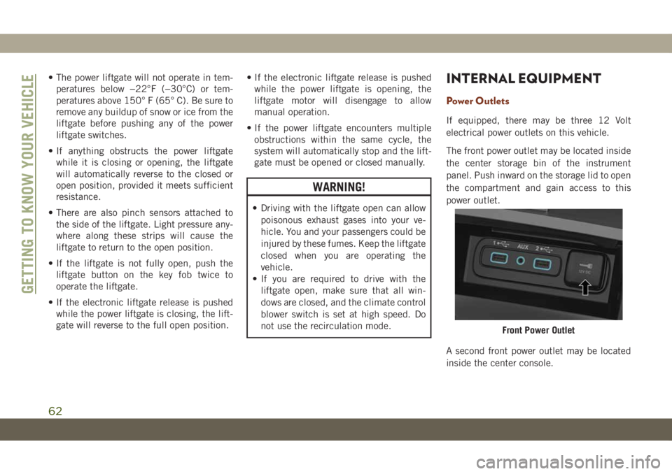
The front power outlet may be located inside
the center storage bin of the instrument
panel. Push inward on the storage lid to open
the compartment and gain access to this
power outlet.
A second front power outlet may be located
inside the center console.
Front Power Outlet
GETTING TO KNOW YOUR VEHICLE
62
Page 82 of 378
hicle start-ups as long as the malfunction
exists. When the malfunction indicator is
illuminated, the system may not be able to
detect or signal low tire pressure as intended.
TPMS malfunctions may occur for a variety of
reasons, including the installation of replace-
ment or alternate tires or wheels on the ve-
hicle that prevent the TPMS from functioning
properly. Always check the TPMS malfunc-
tion telltale after replacing one or more tires
or wheels on your vehicle to ensure that the
replacement or alternate tires and wheels
allow the TPMS to continue to function
properly.
CAUTION!
The TPMS has been optimized for the
original equipment tires and wheels.
TPMS pressures and warning have been
established for the tire size equipped on
your vehicle. Undesirable system opera-
tion or sensor damage may result when
using replacement equipment that is not
of the same size, type, and/or style. After-
market wheels can cause sensor damage.
Using aftermarket tire sealants may cause
CAUTION!
the Tire Pressure Monitoring System
(TPMS) sensor to become inoperable. Af-
ter using an aftermarket tire sealant it is
recommended that you take your vehicle
to your authorized dealer to have your
sensor function checked.
The system only warns the tire pressure is
low: it is not able to inflate them.
Yellow Indicator Lights
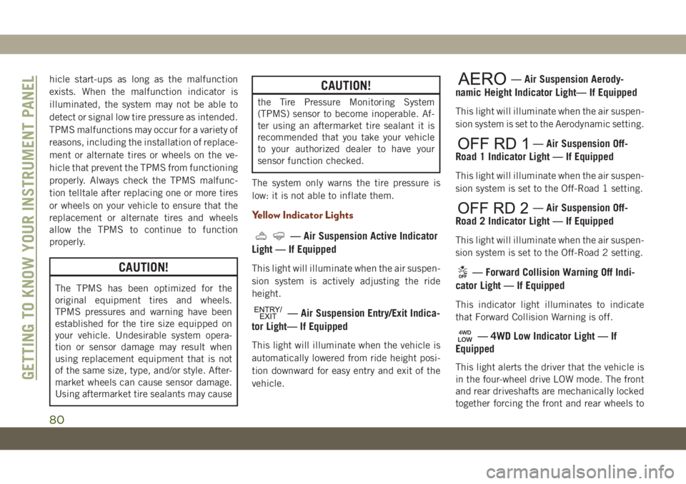
— Air Suspension Active Indicator
Light — If Equipped
This light will illuminate when the air suspen-
sion system is actively adjusting the ride
height.
— Air Suspension Entry/Exit Indica-
tor Light— If Equipped
This light will illuminate when the vehicle is
automatically lowered from ride height posi-
tion downward for easy entry and exit of the
vehicle.
— Air Suspension Aerody-
namic Height Indicator Light— If Equipped
This light will illuminate when the air suspen-
sion system is set to the Aerodynamic setting.
— Air Suspension Off-
Road 1 Indicator Light — If Equipped
This light will illuminate when the air suspen-
sion system is set to the Off-Road 1 setting.
— Air Suspension Off-
Road 2 Indicator Light — If Equipped
This light will illuminate when the air suspen-
sion system is set to the Off-Road 2 setting.
— Forward Collision Warning Off Indi-
cator Light — If Equipped
This indicator light illuminates to indicate
that Forward Collision Warning is off.
— 4WD Low Indicator Light — If
Equipped
This light alerts the driver that the vehicle is
in the four-wheel drive LOW mode. The front
and rear driveshafts are mechanically locked
together forcing the front and rear wheels toGETTING TO KNOW YOUR INSTRUMENT PANEL
80
Page 92 of 378
ESC uses sensors in the vehicle to determine
the vehicle path intended by the driver and
compares it to the actual path of the vehicle.
When the actual path does not match the
intended path, ESC applies the brake of the
appropriate wheel to assist in counteracting
the oversteer or understeer condition.
• Oversteer — when the vehicle is turning
more than appropriate for the steering
wheel position.
• Understeer — when the vehicle is turning
less than appropriate for the steering wheel
position.
The “ESC Activation/Malfunction Indicator
Light” located in the instrument cluster will
start to flash as soon as the ESC system
becomes active. The “ESC Activation/
Malfunction Indicator Light” also flashes
when the TCS is active. If the “ESC
Activation/Malfunction Indicator Light” be-
gins to flash during acceleration, ease up on
the accelerator and apply as little throttle as
possible. Be sure to adapt your speed and
driving to the prevailing road conditions.WARNING!
• Electronic Stability Control (ESC) can-
not prevent the natural laws of physics
from acting on the vehicle, nor can it
increase the traction afforded by prevail-
ing road conditions. ESC cannot prevent
accidents, including those resulting
from excessive speed in turns, driving on
very slippery surfaces, or hydroplaning.
ESC also cannot prevent accidents re-
sulting from loss of vehicle control due
to inappropriate driver input for the con-
ditions. Only a safe, attentive, and skill-
ful driver can prevent accidents. The
capabilities of an ESC equipped vehicle
must never be exploited in a reckless or
dangerous manner which could jeopar-
dize the user’s safety or the safety of
others.
• Vehicle modifications, or failure to prop-
erly maintain your vehicle, may change
the handling characteristics of your ve-
hicle, and may negatively affect the per-
formance of the ESC system. Changes to
the steering system, suspension, brak-
WARNING!
ing system, tire type and size or wheel
size may adversely affect ESC perfor-
mance. Improperly inflated and un-
evenly worn tires may also degrade ESC
performance. Any vehicle modification
or poor vehicle maintenance that re-
duces the effectiveness of the ESC sys-
tem can increase the risk of loss of
vehicle control, vehicle rollover, per-
sonal injury and death.
ESC Operating Modes
NOTE:
Depending upon model and mode of opera-
tion, the ESC system may have multiple op-
erating modes.
ESC On
This is the normal operating mode for the
ESC. Whenever the vehicle is started, the
ESC system will be in this mode. This mode
SAFETY
90
Page 95 of 378
NOTE:
ERM is disabled anytime the ESC is in “Full
Off” mode (if equipped). Refer to “Electronic
Stability Control (ESC)” in this section for a
complete explanation of the available ESC
modes.
WARNING!
Many factors, such as vehicle loading,
road conditions and driving conditions,
influence the chance that wheel lift or
rollover may occur. ERM cannot prevent all
wheel lift or roll overs, especially those
that involve leaving the roadway or striking
objects or other vehicles. The capabilities
of an ERM-equipped vehicle must never
be exploited in a reckless or dangerous
manner which could jeopardize the user's
safety or the safety of others.
Trailer Sway Control (TSC)
TSC uses sensors in the vehicle to recognize
an excessively swaying trailer and will take
the appropriate actions to attempt to stop the
sway. TSC will become active automatically
once an excessively swaying trailer is recog-
nized.
NOTE:
TSC cannot stop all trailers from swaying.
Always use caution when towing a trailer and
follow the trailer tongue weight recommenda-
tions. Refer to “Trailer Towing” in “Starting
And Operating” for further information.
When TSC is functioning, the “ESC
Activation/Malfunction Indicator Light” will
flash, the engine power may be reduced and
you may feel the brakes being applied to
individual wheels to attempt to stop the
trailer from swaying. TSC is disabled when
the ESC system is in the “Partial Off” or “Full
Off” modes.WARNING!
If TSC activates while driving, slow the
vehicle down, stop at the nearest safe
location, and adjust the trailer load to
eliminate trailer sway.
Ready Alert Braking (RAB)
Ready Alert Braking may reduce the time
required to reach full braking during emer-
gency braking situations. It anticipates when
an emergency braking situation may occur by
monitoring how fast the throttle is released by
the driver. The EBC will prepare the brake
system for a panic stop.
Rain Brake Support (RBS)
Rain Brake Support may improve braking
performance in wet conditions. It will periodi-
cally apply a small amount of brake pressure
to remove any water buildup on the front
brake rotors. It functions when the wind-
shield wipers are in LO or HI speed. When
Rain Brake Support is active, there is no
notification to the driver and no driver inter-
action is required.
93
Page 99 of 378
Deactivating SSC
SSC will be deactivated but remain available
if any of the following conditions occur:
• Driver overrides SSC set speed with throttle
or brake application.
• Vehicle speed exceeds 20 mph (32 km/h)
but remains below 40 mph (64 km/h).
• Vehicle is shifted to PARK.
Disabling SSC
SSC will deactivate and be disabled if any of
the following conditions occur:
• The driver pushes the SSC switch.
• The driveline is shifted out of 4WD Low
Range.
• The parking brake is applied.
• Driver door opens.
• The vehicle is driven greater than 20 mph
(32 km/h) for greater than 70 seconds.
• The vehicle is driven greater than 40 mph
(64 km/h) (SSC exits immediately).Feedback To The Driver:
The instrument cluster has an SSC icon and
the SSC switch has an LED which offer feed-
back to the driver about the state SSC is in.
• The cluster icon and switch lamp will illu-
minate and remain on solid when SSC is
enabled or activated. This is the normal
operating condition for SSC.
• The cluster icon and switch lamp will flash
for several seconds then extinguish when
the driver pushes the SSC switch but en-
able conditions are not met.
• The cluster icon and switch lamp will flash
for several seconds then extinguish when
SSC disables due to excess speed.
• The cluster icon and switch lamp will flash
then extinguish when SSC deactivates due
to overheated brakes.WARNING!
SSC is only intended to assist the driver in
controlling vehicle speed when driving in
off road conditions. The driver must re-
main attentive to the driving conditions
and is responsible for maintaining a safe
vehicle speed.
AUXILIARY DRIVING
SYSTEMS
Blind Spot Monitoring (BSM) — If
Equipped
The Blind Spot Monitoring (BSM) system
uses two radar sensors, located inside the
rear bumper fascia, to detect highway licens-
able vehicles (automobiles, trucks, motor-
cycles, etc.) that enter the blind spot zones
from the rear/front/side of the vehicle.
97
Page 100 of 378
When the vehicle is started, the BSM warning
light will momentarily illuminate in both out-
side rear view mirrors to let the driver know
that the system is operational. The BSM
system sensors operate when the vehicle is in
any forward gear or REVERSE.
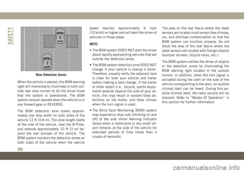
The BSM detection zone covers approxi-
mately one lane width on both sides of the
vehicle 12 ft (3.8 m). The zone length starts
at the side of the vehicle, near the B-Pillar,
and extends approximately 10 ft (3 m) be-
yond the rear bumper of the vehicle. The
BSM system monitors the detection zones on
both sides of the vehicle when the vehiclespeed reaches approximately 6 mph
(10 km/h) or higher and will alert the driver of
vehicles in these areas.
NOTE:
• The BSM system DOES NOT alert the driver
about rapidly approaching vehicles that are
outside the detection zones.
• The BSM system detection zone DOES NOT
change if your vehicle is towing a trailer.
Therefore, visually verify the adjacent lane
is clear for both your vehicle and trailer
before making a lane change. If the trailer
or other object (i.e., bicycle, sports equip-
ment) extends beyond the side of your ve-
hicle, this may result in random false de-
tections on the trailer, and false chimes
when the turn signal is used.
• The Blind Spot Monitoring (BSM) system
may experience drop outs (blinking on and
off) of the side mirror Warning Indicator
lamps when a motorcycle or any small ob-
ject remains at the side of the vehicle for
extended periods of time (more than a
couple of seconds).The area on the rear fascia where the radar
sensors are located must remain free of snow,
ice, and dirt/road contamination so that the
BSM system can function properly. Do not
block the area of the rear fascia where the
radar sensors are located with foreign objects
(bumper stickers, bicycle racks, etc.).
The BSM system notifies the driver of objects
in the detection zones by illuminating the
BSM warning light located in the outside
mirrors. In addition, when the turn signal is
activated during the alert on the side of the
vehicle corresponding to the alert, an audible
(chime) alert can be heard. During this au-
dible (chime) alert, the radio volume will be
reduced. Refer to “Modes Of Operation” in
this section for further information.
Rear Detection Zones
SAFETY
98
Page 102 of 378
(8 km/h), to objects moving a maximum of
approximately 20 mph (32 km/h), such as in
parking lot situations.
NOTE:
In a parking lot situation, oncoming vehicles
can be obscured by vehicles parked on either
side. If the sensors are blocked by other
structures or vehicles, the system will not be
able to alert the driver.
When RCP is on and the vehicle is in RE-
VERSE, the driver is alerted using both the
visual and audible alarms, including reduc-
ing the radio volume.
WARNING!
Rear Cross Path Detection (RCP) is not a
back up aid system. It is intended to be
used to help a driver detect an oncoming
vehicle in a parking lot situation. Drivers
must be careful when backing up, even
when using RCP. Always check carefully
behind your vehicle, look behind you, and
be sure to check for pedestrians, animals,
other vehicles, obstructions, and blind
spots before backing up. Failure to do so
can result in serious injury or death.
Modes Of Operation
Three selectable modes of operation are
available in the Uconnect System. Refer to
“Uconnect Settings” in “Multimedia” in the
Owner’s Manual for further information.
Blind Spot Alert Lights Only
When operating in Blind Spot Alert mode, the
BSM system will provide a visual alert in the
appropriate side view mirror based on a de-
tected object. However, when the system is
operating in Rear Cross Path (RCP) mode, the
system will respond with both visual and
audible alerts when a detected object is pres-
ent. Whenever an audible alert is requested,
the radio is muted.
Blind Spot Alert Lights/Chime
When operating in Blind Spot Alert Lights/
Chime mode, the BSM system will provide a
visual alert in the appropriate side view mirror
based on a detected object. If the turn signal
is then activated, and it corresponds to an
alert present on that side of the vehicle, an
audible chime will also be sounded. When-
ever a turn signal and detected object are
present on the same side at the same time,both the visual and audible alerts will be
issued. In addition to the audible alert the
radio (if on) will also be muted.
NOTE:
Whenever an audible alert is requested by the
BSM system, the radio is also muted.
When the system is in RCP, the system shall
respond with both visual and audible alerts
when a detected object is present. Whenever
an audible alert is requested, the radio is also
muted. Turn/hazard signal status is ignored;
the RCP state always requests the chime.
Blind Spot Alert Off
When the BSM system is turned off there will
be no visual or audible alerts from either the
BSM or RCP systems.
NOTE:
The BSM system will store the current oper-
ating mode when the vehicle is shut off. Each
time the vehicle is started the previously
stored mode will be recalled and used.
SAFETY
100
Page 103 of 378
Forward Collision Warning (FCW) With
Mitigation
The Forward Collision Warning (FCW) with
Mitigation system provides the driver with
audible warnings, visual warnings (within the
instrument cluster display), and may apply a
brake jerk to warn the driver when it detects a
potential frontal collision. The warnings and
limited braking are intended to provide the
driver with enough time to react, avoid or
mitigate the potential collision.
NOTE:
FCW monitors the information from the for-
ward looking sensors as well as the Electronic
Brake Controller (EBC), to calculate the prob-
ability of a forward collision. When the sys-
tem determines that a forward collision is
probable, the driver will be provided with
audible and visual warnings and may provide
a brake jerk warning. If the driver does not
take action based upon these progressive
warnings, then the system will provide a lim-
ited level of active braking to help slow the
vehicle and mitigate the potential forward
collision. If the driver reacts to the warningsby braking and the system determines that
the driver intends to avoid the collision by
braking but has not applied sufficient brake
force, the system will compensate and pro-
vide additional brake force as required.
If a Forward Collision Warning with Mitigation
event begins at a speed below 26 mph
(42 km/h), the system may provide the maxi-
mum or partial braking to mitigate the poten-
tial forward collision. If the Forward Collision
Warning with Mitigation event stops the ve-
hicle completely, the system will hold the
vehicle at a standstill for two seconds and
then release the brakes.
W
hen the system determines a collision with the
vehicle in front of you is no longer probable, the
warning message will be deactivated.
NOTE:
• The minimum speed for FCW activation is
1 mph (2 km/h).
• The FCW alerts may be triggered on objects
other than vehicles such as guard rails or
sign posts based on the course prediction.
This is expected and is a part of normal
FCW activation and functionality.• It is unsafe to test the FCW system. To
prevent such misuse of the system, after
four Active Braking events within an igni-
tion cycle, the Active Braking portion of
FCW will be deactivated until the next igni-
tion cycle.
• The FCW system is intended for on-road use
only. If the vehicle is taken off-road, the
FCW system should be deactivated to pre-
vent unnecessary warnings to the surround-
ings. If the vehicle enters 4WD Low Range
or ESC Full-Off Mode is active, the FCW
system will be automatically deactivated.
WARNING!
Forward Collision Warning (FCW) is not
intended to avoid a collision on its own,
nor can FCW detect every type of potential
collision. The driver has the responsibility
to avoid a collision by controlling the ve-
hicle via braking and steering. Failure to
follow this warning could lead to serious
injury or death.
101