warning light JEEP GRAND CHEROKEE LAREDO 2012 Owners Manual
[x] Cancel search | Manufacturer: JEEP, Model Year: 2012, Model line: GRAND CHEROKEE LAREDO, Model: JEEP GRAND CHEROKEE LAREDO 2012Pages: 655, PDF Size: 4.26 MB
Page 51 of 655
WARNING!
During power operation, personal injury or cargo
damage may occur. Ensure the liftgate travel path is
clear. Make sure the liftgate is closed and latched
before driving away.
NOTE:
• The power liftgate buttons will not operate if the
vehicle is in gear or the vehicle speed is above 0 mph
(0 km/h).
• The power liftgate will not operate in temperatures
below �22°F (�30°C) or temperatures above 150°F
(65°C). Be sure to remove any buildup of snow or ice
from the liftgate before pressing any of the power
liftgate switches. •
If anything obstructs the power liftgate while it is
closing or opening, the liftgate will automatically
reverse to the closed or open position, provided it
meets sufficient resistance.
• There are also pinch sensors attached to the side of the
liftgate. Light pressure anywhere along these strips
will cause the liftgate to return to the open position.
• The power liftgate must be in the full open position for
rear liftgate close button on the left rear trim, near the
liftgate opening to operate. If the liftgate is not fully
open, press the Liftgate button on the Key Fob to fully
open the liftgate, and then press it again to close.
• If the liftgate handle is pulled while the power liftgate
is closing, the liftgate will reverse to the full open
position.2
THINGS TO KNOW BEFORE STARTING YOUR VEHICLE 49
Page 74 of 655
WARNING!(Continued)
because the air bags may no longer be functional.
The protective covers for the air bag cushions are
designed to open only when the air bags are
inflating.
• Do not drill, cut or tamper with the knee bolster in
any way.
• Do not mount any accessories to the knee bolster
such as alarm lights, stereos, citizen band radios,
etc.
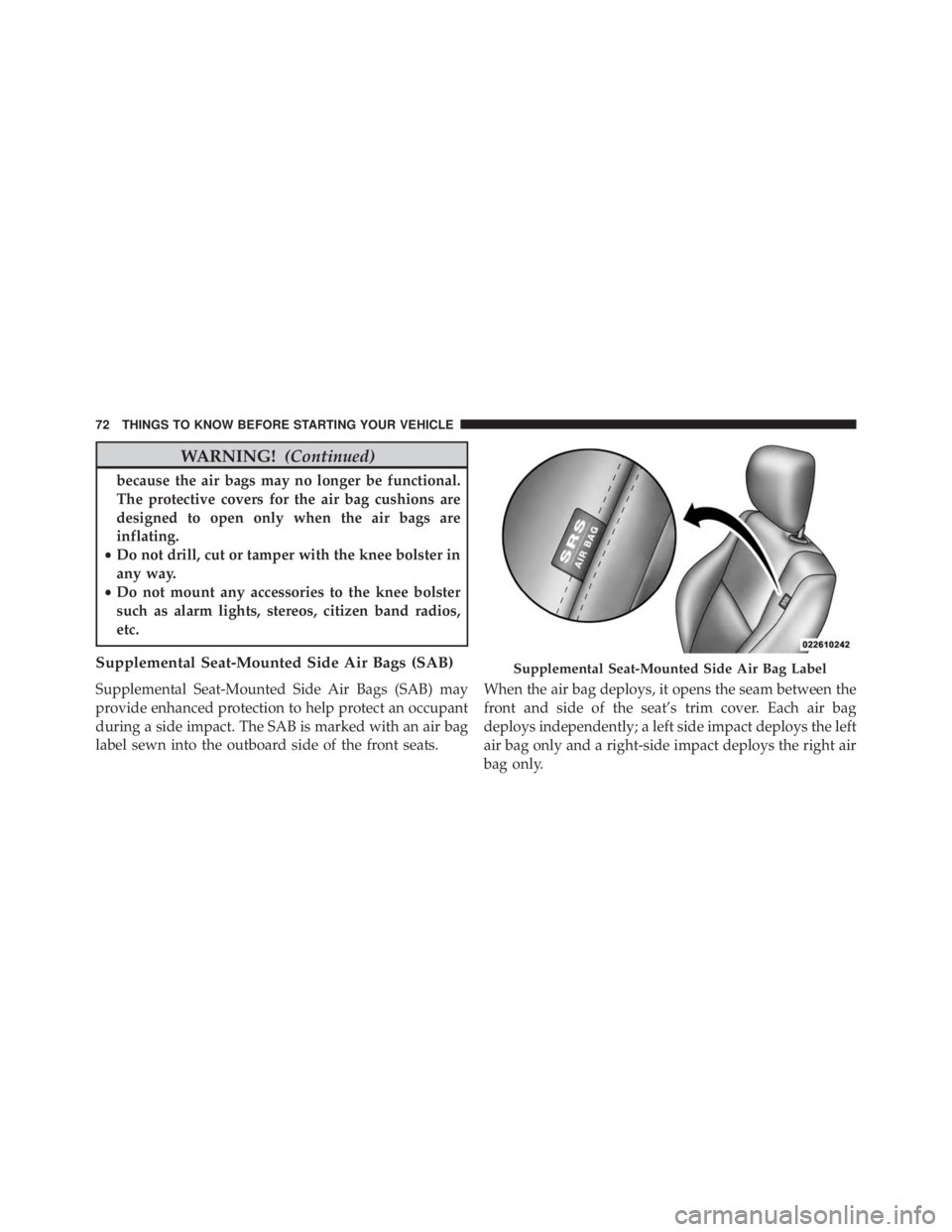
Supplemental Seat-Mounted Side Air Bags (SAB)
Supplemental Seat-Mounted Side Air Bags (SAB) may
provide enhanced protection to help protect an occupant
during a side impact. The SAB is marked with an air bag
label sewn into the outboard side of the front seats. When the air bag deploys, it opens the seam between the
front and side of the seat’s trim cover. Each air bag
deploys independently; a left side impact deploys the left
air bag only and a right-side impact deploys the right air
bag only.
Page 79 of 655
WARNING!
Ignoring the Air Bag Warning Light in your instru-
ment panel could mean you won’t have the air bags
to protect you in a collision. If the light does not come
on as a bulb check when the ignition is first turned
on, stays on after you start the vehicle, or if it comes
on as you drive, have an authorized dealer service the
air bag system immediately.
Driver And Passenger Advanced Front Air Bag
Inflator Units
The Driver and Passenger Advanced Front Air Bag
Inflator Units are located in the center of the steering
wheel and on the right side of the instrument panel.
When the ORC detects a collision requiring the Ad-
vanced Front Air Bags, it signals the inflator units. A large
quantity of non-toxic gas is generated to inflate the
Advanced Front Air Bags. Different air bag inflation ratesare possible, based on several factors, including the
collision type and severity. The steering wheel hub trim
cover and the upper right side of the instrument panel
separate and fold out of the way as the air bags inflate to
their full size. The air bags fully inflate in about 50 to 70
milliseconds. This is about half of the time it takes to
blink your eyes. The air bags then quickly deflate while
helping to restrain the driver and front passenger.
The Advanced Front Air Bag gas is vented through the
vent holes in the sides of the air bag. In this way, the air
bags do not interfere with your control of the vehicle.Supplemental Seat-Mounted Side Air Bag (SAB)
Inflator Units
The Supplemental Seat-Mounted Side Air Bags are de-
signed to activate only in certain side collisions.
2
THINGS TO KNOW BEFORE STARTING YOUR VEHICLE 77
Page 114 of 655
WARNING!(Continued)
•If required, mounting posts must be properly in-
stalled, if not equipped from the factory.
Failure to properly follow floor mat installation or
mounting can cause interference with the brake
pedal and accelerator pedal operation causing loss of
control of the vehicle.
Periodic Safety Checks You Should Make Outside
The Vehicle
Tires
Examine tires for excessive tread wear and uneven wear
patterns. Check for stones, nails, glass, or other objects
lodged in the tread or sidewall. Inspect the tread for cuts
and cracks. Inspect sidewalls for cuts, cracks and bulges.
Check the wheel nuts for tightness. Check the tires
(including spare) for proper cold inflation pressure.
Lights
Have someone observe the operation of brake lights and
exterior lights while you work the controls. Check turn
signal and high beam indicator lights on the instrument
panel.
Door Latches
Check for positive closing, latching, and locking.
Fluid Leaks
Check area under vehicle after overnight parking for fuel,
engine coolant, oil, or other fluid leaks. Also, if gasoline
fumes are detected or if fuel, power steering fluid, or
brake fluid leaks are suspected, the cause should be
located and corrected immediately.
112 THINGS TO KNOW BEFORE STARTING YOUR VEHICLE
Page 313 of 655
Brake Booster has been detected by the Anti-Lock Brake
System (ABS) / Electronic Stability Control (ESC) system.
In this case, the light will remain on until the condition
has been corrected. If the problem is related to the brake
booster, the ABS pump will run when applying the brake
and a brake pedal pulsation may be felt during each stop.
The dual brake system provides a reserve braking capac-
ity in the event of a failure to a portion of the hydraulic
system. A leak in either half of the dual brake system is
indicated by the Brake Warning Light, which will turn on
when the brake fluid level in the master cylinder has
dropped below a specified level.
The light will remain on until the cause is corrected.
NOTE:The light may flash momentarily during sharp
cornering maneuvers, which change fluid level condi-
tions. The vehicle should have service performed, and
the brake fluid level checked. If brake failure is indicated, immediate repair is neces-
sary.
Page 332 of 655
chime will sound after reaching a set threshold. Further
overheating will cause the temperature gauge to passH,
the indicator will continuously flash and a continuous
chime will occur until the engine is allowed to cool.
If the light turns on while driving, safely pull over and
stop the vehicle. If the A/C system is on, turn it off. Also,
shift the transmission into NEUTRAL and idle the ve-
hicle. If the temperature reading does not return to
normal, turn the engine off immediately and call for
service. Refer to “If Your Engine Overheats” in “What To
Do In Emergencies” for more information.
• Transmission Temperature Warning Light
This light indicates that there is excessive trans-
mission fluid temperature that might occur
with severe usage such as trailer towing. It may
also occur when operating the vehicle in a high
torque converter slip condition, such as 4-wheel-drive
operation (e.g., snow plowing, off- road operation). If this light comes on, stop the vehicle and run the engine at idle
or faster, with the transmission in NEUTRAL until the
light goes off.
Page 467 of 655
NOTE:
•When the parking brake is applied and the transmis-
sion is placed in gear, the “Brake Warning Light” will
flash. If vehicle speed is detected, a chime will sound
to alert the driver. Fully release the parking brake
before attempting to move the vehicle.
• This light only shows that the parking brake is ap-
plied. It does not show the degree of brake application.
When parking on a hill, it is important to turn the front
wheels toward the curb on a downhill grade and away
from the curb on an uphill grade. Apply the parking
brake before placing the shift lever in PARK, otherwise
the load on the transmission locking mechanism may
make it difficult to move the shift lever out of PARK. The
parking brake should always be applied whenever the
driver is not in the vehicle.
Page 471 of 655

WARNING!
Many factors, such as vehicle loading, road condi-
tions, and driving conditions, influence the chance
that wheel lift or rollover may occur. ERM cannot
prevent all wheel lift or rollovers, especially those
that involve leaving the roadway or striking objects
or other vehicles. The capabilities of an ERM-
equipped vehicle must never be exploited in a reck-
less or dangerous manner, which could jeopardize
the user’s safety or the safety of others.
Electronic Stability Control (ESC)
This system enhances directional control and stability of
the vehicle under various driving conditions. ESC cor-
rects for oversteering or understeering of the vehicle by
applying the brake of the appropriate wheel to assist incounteracting the oversteer or understeer condition. En-
gine power may also be reduced to help the vehicle
maintain the desired path.
ESC uses sensors in the vehicle to determine the vehicle
path intended by the driver and compares it to the actual
path of the vehicle. When the actual path does not match
the intended path, ESC applies the brake of the appro-
priate wheel to assist in counteracting the oversteer or
understeer condition.
•
Oversteer - when the vehicle is turning more than
appropriate for the steering wheel position.
• Understeer - when the vehicle is turning less than
appropriate for the steering wheel position.
The “ESC Activation/Malfunction Indicator Light” lo-
cated in the instrument cluster will start to flash as soon
as the tires lose traction and the ESC system becomes
active. The “ESC Activation/Malfunction Indicator
Light” also flashes when the TCS is active. If the “ESC
5
STARTING AND OPERATING 469
Page 539 of 655

WARNING!
Raising the vehicle higher than necessary can make
the vehicle less stable. It could slip off the jack and
hurt someone near it. Raise the vehicle only enough
to remove the tire.
7. Remove the lug nuts and wheel.
8. Position the spare wheel/tire on the vehicle and install the lug nuts with the cone-shaped end toward the
wheel. Lightly tighten the nuts.
Page 541 of 655
WARNING!
A loose tire or jack thrown forward in a collision or
hard stop could endanger the occupants of the ve-
hicle. Always stow the jack parts and the spare tire in
the places provided. Have the deflated (flat) tire
repaired or replaced immediately.
Road Tire Installation
1. Mount the road tire on the axle.
2. Install the remaining lug nuts with the cone shapedend of the nut toward the wheel. Lightly tighten the
lug nuts.