headlamp JEEP GRAND CHEROKEE LIMITED 2019 Owners Manual
[x] Cancel search | Manufacturer: JEEP, Model Year: 2019, Model line: GRAND CHEROKEE LIMITED, Model: JEEP GRAND CHEROKEE LIMITED 2019Pages: 626, PDF Size: 3.77 MB
Page 75 of 626
•The DRL function may be disabled through the
Uconnect system. Refer to “Uconnect Settings” in “Mul-
timedia” for further information.
The headlight switch must be used for normal nighttime
driving.
High/Low Beam Switch
Push the multifunction lever toward the instrument panel
to switch the headlights to high beams. Pulling the multi-
function back toward the steering wheel will turn the low
beams back on, or shut the high beams off.
Automatic High Beam — If Equipped
The Automatic High Beam Headlamp Control system
provides increased forward lighting at night by automat-
ing high beam control through the use of a digital camera
mounted on the inside rearview mirror. This camera de-
tects vehicle specific light and automatically switches from
high beams to low beams until the approaching vehicle is
out of view. NOTE:
•
The Automatic High Beam Headlamp Control can be
turned on or off by selecting “ON” under “Auto High
Beam” within your Uconnect settings, as well as turning
the headlight switch to the AUTO position. Refer to
“Uconnect Settings” in “Multimedia” for further infor-
mation.
• Broken, muddy, or obstructed headlights and taillights
of vehicles in the field of view will cause headlights to
remain on longer (closer to the vehicle). Also, dirt, film,
and other obstructions on the windshield or camera lens
will cause the system to function improperly.
If the windshield or Automatic High Beam Headlamp
Control mirror is replaced, the mirror must be re-aimed to
ensure proper performance. See a local authorized dealer.
Flash-To-Pass
You can signal another vehicle with your headlights by
lightly pulling the multifunction lever toward you. This
will cause the high beam headlights to turn on, and remain
on, until the lever is released.
3
GETTING TO KNOW YOUR VEHICLE 73
Page 225 of 626
Your vehicle may also be designed to perform any of these
other functions in response to the Enhanced Accident
Response System:
•Turn off the Fuel Filter Heater, Turn off the HVAC
Blower Motor, Close the HVAC Circulation Door
• Cut off battery power to the:
• Engine
• Electric Motor (if equipped)
• Electric power steering
• Brake booster
• Electric park brake
• Automatic transmission gear selector
• Horn
• Front wiper
• Headlamp washer pump NOTE:
After an accident, remember to cycle the ignition
to the STOP (OFF/LOCK) position and remove the key
from the ignition switch to avoid draining the battery.
Carefully check the vehicle for fuel leaks in the engine
compartment and on the ground near the engine compart-
ment and fuel tank before resetting the system and starting
the engine. If there are no fuel leaks or damage to the
vehicle electrical devices (e.g. headlights) after an accident,
reset the system by following the procedure described
below. If you have any doubt, contact an authorized dealer.
Enhanced Accident Response System Reset
Procedure
In order to reset the Enhanced Accident Response System
functions after an event, the ignition switch must be
changed from ignition START or ON/RUN to ignition OFF.
Carefully check the vehicle for fuel leaks in the engine
compartment and on the ground near the engine compart-
ment and fuel tank before resetting the system and starting
the engine.
5
SAFETY 223
Page 361 of 626
NOTE:If snow, ice, mud, or any foreign substance builds
up on the camera lens, clean the lens, rinse with water, and
dry with a soft cloth. Do not cover the lens.
Rear Camera — Viewing At Speed
When the vehicle is in park, neutral or drive, the Rear View
Camera can be activated with the “Rear View Camera”
button
in the Controls menu. This feature allows the
customer to monitor the area directly behind the vehicle
(or trailer, if equipped) for up to ten seconds while at
speed. If the vehicle speed remains below 8 mph
(13 km/h), the Rear View Camera image will be dis-
played continuously until deactivated via the “X” but-
ton on the touchscreen. REFUELING THE VEHICLE — GASOLINE ENGINE
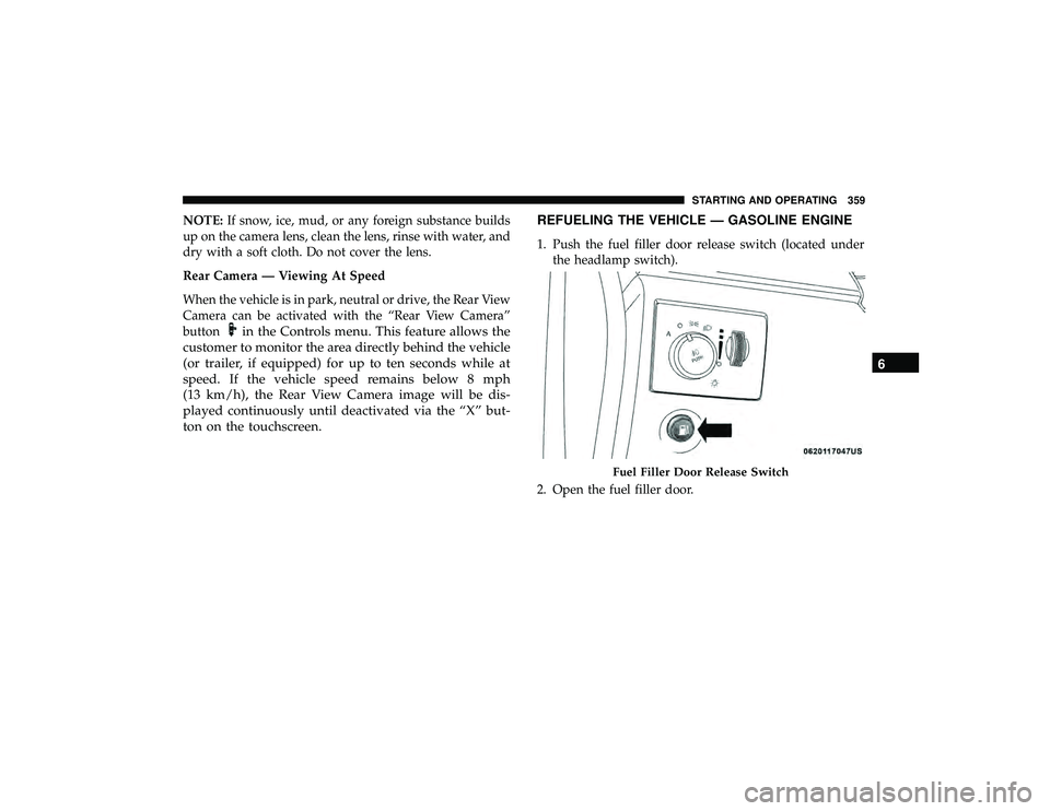
1. Push the fuel filler door release switch (located under
the headlamp switch).
2. Open the fuel filler door.
Page 402 of 626
Bulb Replacement
High Intensity Discharge Headlamps (HID) — If
Equipped
The headlamps are a type of high voltage discharge tube.
High voltage can remain in the circuit even with the
headlamp switch off and the key removed.Because of this,
you should not attempt to service a headlamp bulb
yourself. If a headlamp bulb fails, take your vehicle to an
authorized dealer for service.
WARNING!
A transient high voltage occurs at the bulb sockets of
High Intensity Discharge (HID) headlamps when the
headlamp switch is turned ON. It may cause serious
electrical shock or electrocution if not serviced prop-
erly. See your authorized dealer for service.
NOTE: On vehicles equipped with High Intensity Dis-
charge (HID) headlamps, when the headlamps are turned
on, there is a blue hue to the lamps. This diminishes and
becomes more white after approximately 10 seconds, as the
system charges.
Halogen Headlamps — If Equipped
NOTE: Lens fogging can occur under certain atmospheric
conditions. This will usually clear as atmospheric condi-
tions change to allow the condensation to change back to
vapor. Turning the lamps on will usually accelerate the
clearing process.
1. Open the hood.
2. Access the back of the headlamp.
NOTE:
•The air filter housing must be removed.
• The windshield washer reservoir may need to be
rotated out of the way by removing the fastener.
• Coolant reservoir (if equipped) will need to be reposi-
tioned by removing the fasteners, and moving the unit
out of the way.
3. To access the low beam bulb you must remove the rubber boot seal from backside of the lamp housing.
400 IN CASE OF EMERGENCY
Page 410 of 626
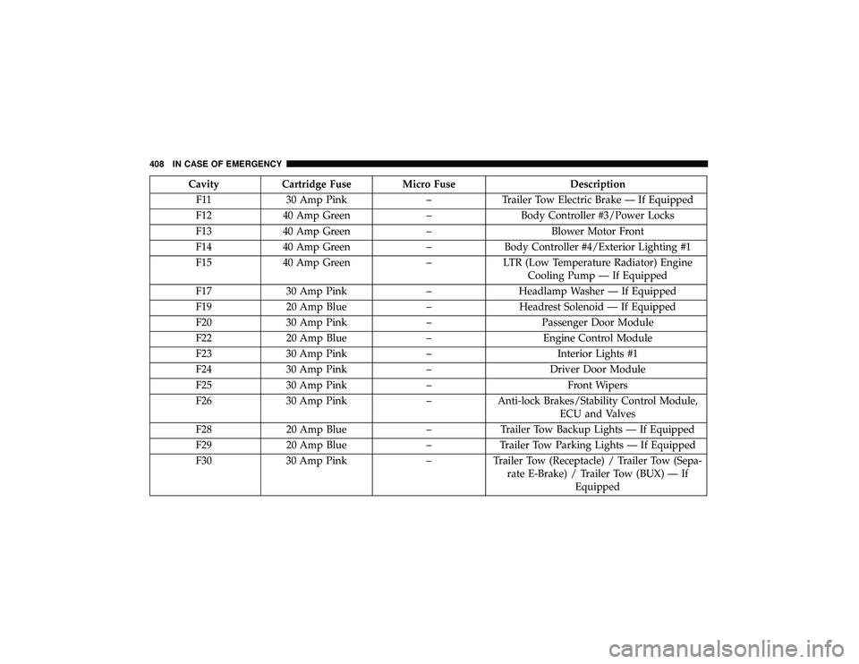
CavityCartridge Fuse Micro Fuse Description
F11 30 Amp Pink –Trailer Tow Electric Brake — If Equipped
F12 40 Amp Green –Body Controller #3/Power Locks
F13 40 Amp Green –Blower Motor Front
F14 40 Amp Green –Body Controller #4/Exterior Lighting #1
F15 40 Amp Green –LTR (Low Temperature Radiator) Engine
Cooling Pump — If Equipped
F17 30 Amp Pink –Headlamp Washer — If Equipped
F19 20 Amp Blue –Headrest Solenoid — If Equipped
F20 30 Amp Pink –Passenger Door Module
F22 20 Amp Blue –Engine Control Module
F23 30 Amp Pink –Interior Lights #1
F24 30 Amp Pink –Driver Door Module
F25 30 Amp Pink – Front Wipers
F26 30 Amp Pink –Anti-lock Brakes/Stability Control Module,
ECU and Valves
F28 20 Amp Blue –Trailer Tow Backup Lights — If Equipped
F29 20 Amp Blue –Trailer Tow Parking Lights — If Equipped
F30 30 Amp Pink –Trailer Tow (Receptacle) / Trailer Tow (Sepa-
rate E-Brake) / Trailer Tow (BUX) — If Equipped
408 IN CASE OF EMERGENCY
Page 411 of 626
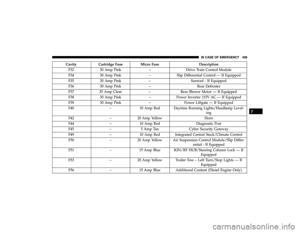
CavityCartridge Fuse Micro Fuse Description
F32 30 Amp Pink –Drive Train Control Module
F34 30 Amp Pink –Slip Differential Control — If Equipped
F35 30 Amp Pink –Sunroof - If Equipped
F36 30 Amp Pink –Rear Defroster
F37 25 Amp Clear –Rear Blower Motor — If Equipped
F38 30 Amp Pink –Power Inverter 115V AC — If Equipped
F39 30 Amp Pink –Power Liftgate — If Equipped
F40 –10 Amp Red Daytime Running Lights/Headlamp Level-
ing
F42 –20 Amp Yellow Horn
F44 –10 Amp Red Diagnostic Port
F45 –5 Amp Tan Cyber Security Gateway
F49 –10 Amp Red Integrated Central Stack/Climate Control
F50 –20 Amp Yellow Air Suspension Control Module/Slip Differ-
ential - If Equipped
F51 –15 Amp Blue KIN/RF HUB/Steering Column Lock — If
Equipped
F53 –20 Amp Yellow Trailer Tow – Left Turn/Stop Lights — If
Equipped
F56 –15 Amp Blue Additional Content (Diesel Engine Only)
7
IN CASE OF EMERGENCY 409
Page 412 of 626
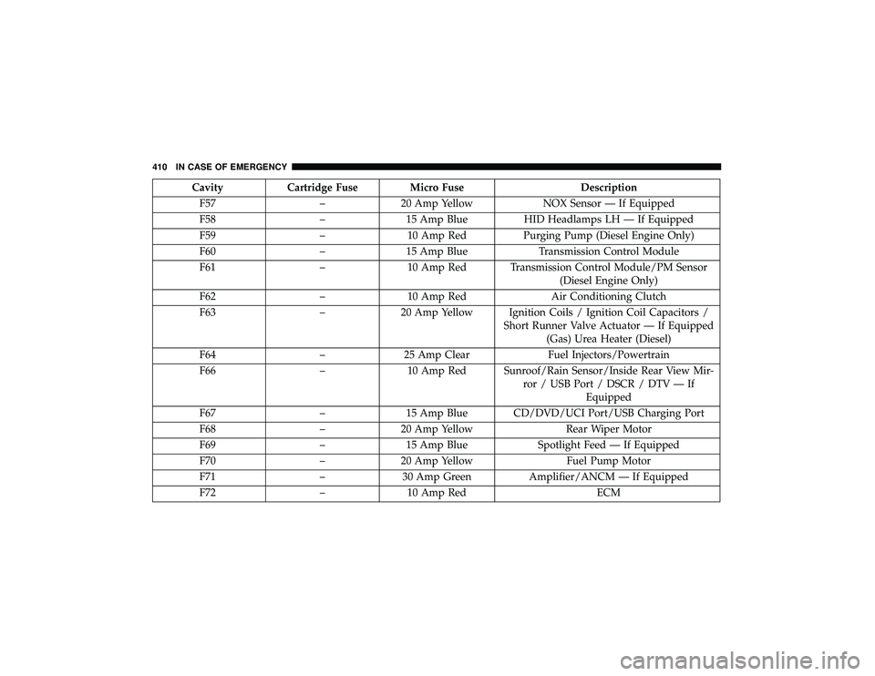
CavityCartridge Fuse Micro Fuse Description
F57 –20 Amp Yellow NOX Sensor — If Equipped
F58 –15 Amp Blue HID Headlamps LH — If Equipped
F59 –10 Amp Red Purging Pump (Diesel Engine Only)
F60 –15 Amp Blue Transmission Control Module
F61 –10 Amp Red Transmission Control Module/PM Sensor
(Diesel Engine Only)
F62 –10 Amp Red Air Conditioning Clutch
F63 –20 Amp Yellow Ignition Coils / Ignition Coil Capacitors /
Short Runner Valve Actuator — If Equipped(Gas) Urea Heater (Diesel)
F64 –25 Amp Clear Fuel Injectors/Powertrain
F66 –10 Amp Red Sunroof/Rain Sensor/Inside Rear View Mir-
ror / USB Port / DSCR / DTV — IfEquipped
F67 –15 Amp Blue CD/DVD/UCI Port/USB Charging Port
F68 –20 Amp Yellow Rear Wiper Motor
F69 –15 Amp Blue Spotlight Feed — If Equipped
F70 –20 Amp Yellow Fuel Pump Motor
F71 –30 Amp Green Amplifier/ANCM — If Equipped
F72 –10 Amp Red ECM
410 IN CASE OF EMERGENCY
Page 413 of 626
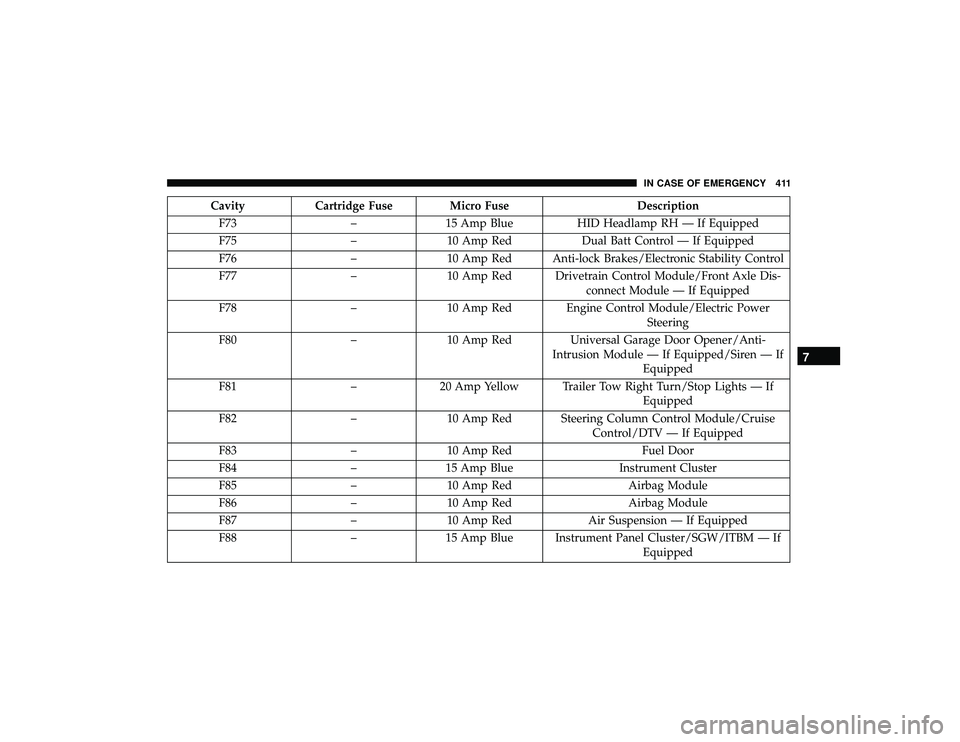
CavityCartridge Fuse Micro Fuse Description
F73 –15 Amp Blue HID Headlamp RH — If Equipped
F75 –10 Amp Red Dual Batt Control — If Equipped
F76 –10 Amp Red Anti-lock Brakes/Electronic Stability Control
F77 –10 Amp Red Drivetrain Control Module/Front Axle Dis-
connect Module — If Equipped
F78 –10 Amp Red Engine Control Module/Electric Power
Steering
F80 –10 Amp Red Universal Garage Door Opener/Anti-
Intrusion Module — If Equipped/Siren — If Equipped
F81 –20 Amp Yellow Trailer Tow Right Turn/Stop Lights — If
Equipped
F82 –10 Amp Red Steering Column Control Module/Cruise
Control/DTV — If Equipped
F83 –10 Amp Red Fuel Door
F84 –15 Amp Blue Instrument Cluster
F85 –10 Amp Red Airbag Module
F86 –10 Amp Red Airbag Module
F87 –10 Amp Red Air Suspension — If Equipped
F88 –15 Amp Blue Instrument Panel Cluster/SGW/ITBM — If
Equipped
7
IN CASE OF EMERGENCY 411