tow rating JEEP LIBERTY 2002 KJ / 1.G User Guide
[x] Cancel search | Manufacturer: JEEP, Model Year: 2002, Model line: LIBERTY, Model: JEEP LIBERTY 2002 KJ / 1.GPages: 1803, PDF Size: 62.3 MB
Page 1283 of 1803

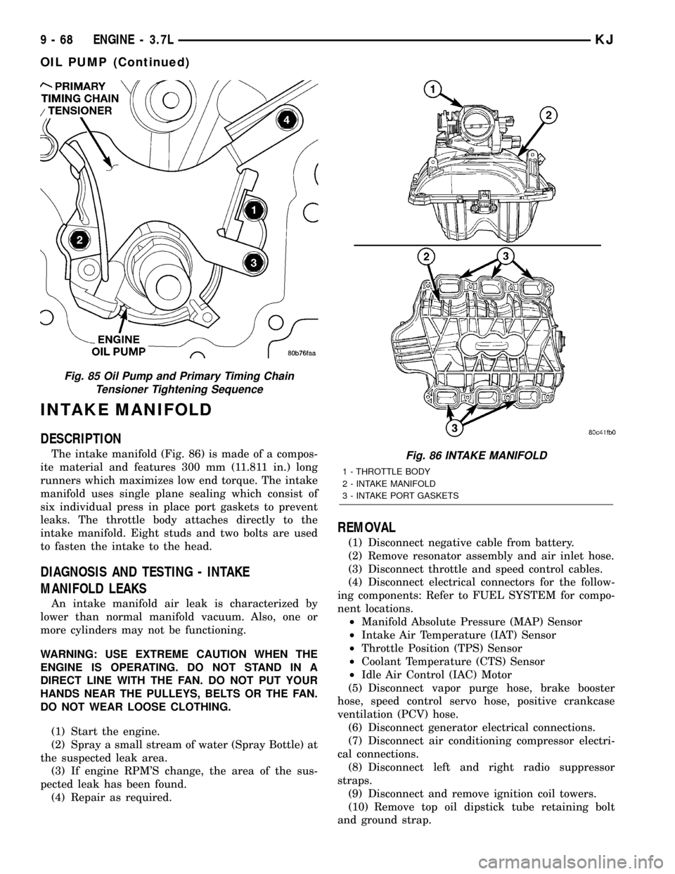
INTAKE MANIFOLD
DESCRIPTION
The intake manifold (Fig. 86) is made of a compos-
ite material and features 300 mm (11.811 in.) long
runners which maximizes low end torque. The intake
manifold uses single plane sealing which consist of
six individual press in place port gaskets to prevent
leaks. The throttle body attaches directly to the
intake manifold. Eight studs and two bolts are used
to fasten the intake to the head.
DIAGNOSIS AND TESTING - INTAKE
MANIFOLD LEAKS
An intake manifold air leak is characterized by
lower than normal manifold vacuum. Also, one or
more cylinders may not be functioning.
WARNING: USE EXTREME CAUTION WHEN THE
ENGINE IS OPERATING. DO NOT STAND IN A
DIRECT LINE WITH THE FAN. DO NOT PUT YOUR
HANDS NEAR THE PULLEYS, BELTS OR THE FAN.
DO NOT WEAR LOOSE CLOTHING.
(1) Start the engine.
(2) Spray a small stream of water (Spray Bottle) at
the suspected leak area.
(3) If engine RPM'S change, the area of the sus-
pected leak has been found.
(4) Repair as required.
REMOVAL
(1) Disconnect negative cable from battery.
(2) Remove resonator assembly and air inlet hose.
(3) Disconnect throttle and speed control cables.
(4) Disconnect electrical connectors for the follow-
ing components: Refer to FUEL SYSTEM for compo-
nent locations.
²Manifold Absolute Pressure (MAP) Sensor
²Intake Air Temperature (IAT) Sensor
²Throttle Position (TPS) Sensor
²Coolant Temperature (CTS) Sensor
²Idle Air Control (IAC) Motor
(5) Disconnect vapor purge hose, brake booster
hose, speed control servo hose, positive crankcase
ventilation (PCV) hose.
(6) Disconnect generator electrical connections.
(7) Disconnect air conditioning compressor electri-
cal connections.
(8) Disconnect left and right radio suppressor
straps.
(9) Disconnect and remove ignition coil towers.
(10) Remove top oil dipstick tube retaining bolt
and ground strap.
Fig. 85 Oil Pump and Primary Timing Chain
Tensioner Tightening Sequence
Fig. 86 INTAKE MANIFOLD
1 - THROTTLE BODY
2 - INTAKE MANIFOLD
3 - INTAKE PORT GASKETS
9 - 68 ENGINE - 3.7LKJ
OIL PUMP (Continued)
Page 1737 of 1803

OPERATION
The PCV system operates by engine intake mani-
fold vacuum. Filtered air is routed into the crankcase
through the air cleaner hose and crankcase breath-
er(s) (if used). The metered air, along with crankcase
vapors, are drawn through the PCV valve and into a
passage in the intake manifold. The PCV system
manages crankcase pressure and meters blow-by
gases to the intake system, reducing engine sludge
formation.
The PCV valve contains a spring loaded plunger.
This plunger meters the amount of crankcase vapors
routed into the combustion chamber based on intake
manifold vacuum.
TYPICALPCV valves are shown in (Fig. 9), (Fig.
10) and (Fig. 11).
When the engine is not operating, or during an
engine pop-back, the spring forces the plunger back
against the seat (Fig. 9). This will prevent vapors
from flowing through the valve.
During periods of high manifold vacuum, such as
idle or cruising speeds, vacuum is sufficient to com-
pletely compress spring. It will then pull the plunger
to the top of the valve (Fig. 10). In this position there
is minimal vapor flow through the valve.
During periods of moderate manifold vacuum, the
plunger is only pulled part way back from inlet. This
results in maximum vapor flow through the valve
(Fig. 11).
DIAGNOSIS AND TESTING - PCV VALVE
3.7L
(1) Disconnect PCV line/hose (Fig. 7) by discon-
necting rubber connecting hose at PCV valve fitting.
(2) Remove PCV valve at oil filler tube by rotating
PCV valve downward until locating tabs have been
freed at cam lock (Fig. 7). After tabs have cleared,
pull valve straight out from filler tube.To prevent
damage to PCV valve locating tabs, valve must
be pointed downward for removal. Do not force
valve from oil filler tube.
(3) After valve is removed, check condition of valve
o-ring (Fig. 7). Also, PCV valve should rattle when
shaken.
(4) Reconnect PCV valve to its connecting line/
hose.
(5) Start engine and bring to idle speed.
(6) If valve is not plugged, a hissing noise will be
heard as air passes through valve. Also, a strong vac-
uum should be felt with a finger placed at valve
inlet.
(7) If vacuum is not felt at valve inlet, check line/
hose for kinks or for obstruction. If necessary, clean
out intake manifold fitting at rear of manifold. Do
this by turning a 1/4 inch drill (by hand) through the
fitting to dislodge any solid particles. Blow out the
fitting with shop air. If necessary, use a smaller drill
to avoid removing any metal from the fitting.
(8)Do not attempt to clean the old PCV valve.
(9) Return PCV valve back to oil filler tube by
placing valve locating tabs (Fig. 7) into cam lock.
Press PCV valve in and rotate valve upward. A slight
click will be felt when tabs have engaged cam lock.
Valve should be pointed towards rear of vehicle.
(10) Connect PCV line/hose and connecting rubber
hose to PCV valve.
(11) Disconnect rubber hose from fresh air fitting
at air cleaner resonator box. Start engine and bring
to idle speed. Hold a piece of stiff paper (such as a
parts tag) loosely over the opening of the discon-
nected rubber hose.
(12) The paper should be drawn against the hose
opening with noticeable force. This will be after
allowing approximately one minute for crankcase
pressure to reduce.
Fig. 9 Engine Off or Engine Pop-BackÐNo Vapor
Flow
Fig. 10 High Intake Manifold VacuumÐMinimal
Vapor Flow
Fig. 11 Moderate Intake Manifold VacuumÐ
Maximum Vapor Flow
KJEVAPORATIVE EMISSIONS 25 - 31
PCV VALVE (Continued)