Windshield JEEP LIBERTY 2002 KJ / 1.G Owner's Manual
[x] Cancel search | Manufacturer: JEEP, Model Year: 2002, Model line: LIBERTY, Model: JEEP LIBERTY 2002 KJ / 1.GPages: 1803, PDF Size: 62.3 MB
Page 1578 of 1803

Fig. 102 WINDSHIELD OPENING
KJBODY STRUCTURE 23 - 113
OPENING DIMENSIONS (Continued)
Page 1605 of 1803
EXTERIOR
TABLE OF CONTENTS
page page
BODY SIDE MOLDINGS
REMOVAL............................140
INSTALLATION........................140
COWL GRILLE
REMOVAL............................140
INSTALLATION........................140
EXTERIOR NAME PLATES
REMOVAL............................140
INSTALLATION........................141
FRONT FENDER
REMOVAL............................141
INSTALLATION........................141
FUEL FILL DOOR/HOUSING
REMOVAL............................141
INSTALLATION........................141
GRILLE
REMOVAL............................142
INSTALLATION........................142
GRILLE OPENING REINFORCEMENT
REMOVAL............................142
INSTALLATION........................142FRONT WHEELHOUSE SPLASH SHIELD
REMOVAL............................143
INSTALLATION........................143
LUGGAGE RACK
REMOVAL............................144
INSTALLATION........................144
REAR WHEELHOUSE SPLASH SHIELD
REMOVAL............................144
INSTALLATION........................144
SIDE VIEW MIRROR
REMOVAL............................145
INSTALLATION........................145
FRONT WHEEL OPENING FLARE MOLDINGS
REMOVAL............................145
INSTALLATION........................145
REAR WHEEL OPENING FLARE MOLDINGS
REMOVAL............................145
INSTALLATION........................145
RADIATOR CROSSMEMBER
REMOVAL............................146
INSTALLATION........................146
BODY SIDE MOLDINGS
REMOVAL
(1) Using a trim stick C-4755 or equivalent,
remove and discard the molding from the outside of
the door.
INSTALLATION
(1) Thoroughly clean all residue from the body side
molding attachment area of the door.
(2) Wipe area clean with a 50% solution of water
and alcohol and wipe dry.
(3) Apply new body side molding using the locators
in the door and apply pressure of approximately 40
p.s.i. over the entire surface of the molding.
COWL GRILLE
REMOVAL
(1) Remove the hood seal.
(2) Remove the wiper arms. (Refer to 8 - ELEC-
TRICAL/WIPERS/WASHERS/WIPER ARMS -
REMOVAL)
(3) Remove the four plastic retainers and remove
the cowl grill.
INSTALLATION
(1) Position the cowl grill and engage the nine
clips to the bottom of the windshield.
(2) Install the five plastic retainers.
(3) Install the wiper arms. (Refer to 8 - ELECTRI-
CAL/WIPERS/WASHERS/WIPER ARMS - INSTAL-
LATION)
(4) Install the hood seal.
EXTERIOR NAME PLATES
REMOVAL
NOTE: Exterior nameplates are attached to body
panels with adhesive tape.
(1) Apply a length of masking tape on the body,
parallel to the top edge of the nameplate to use as a
guide, if necessary.
(2) If temperature is below 21ÉC (70ÉF) warm
emblem with a heat lamp or gun. Do not exceed 52ÉC
(120ÉF) when heating emblem.
(3) Using a trim stick C-4755 or equivalent, behind
the emblem to separate the adhesive backing from
the body.
23 - 140 EXTERIORKJ
Page 1626 of 1803
REAR VIEW MIRROR
REMOVAL
(1) If equipped, disconnect mirror harness connec-
tor.
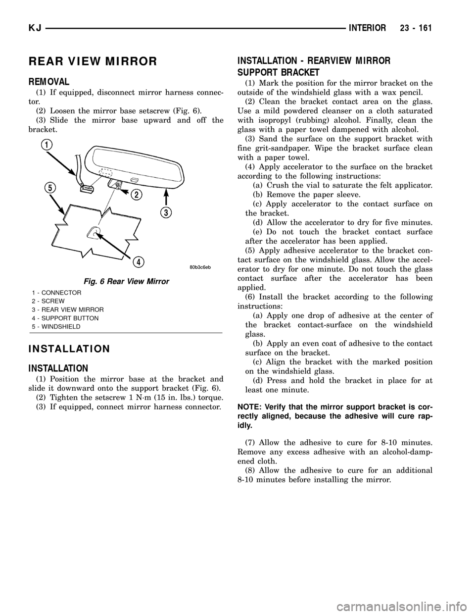
(2) Loosen the mirror base setscrew (Fig. 6).
(3) Slide the mirror base upward and off the
bracket.
INSTALLATION
INSTALLATION
(1) Position the mirror base at the bracket and
slide it downward onto the support bracket (Fig. 6).
(2) Tighten the setscrew 1 N´m (15 in. lbs.) torque.
(3) If equipped, connect mirror harness connector.
INSTALLATION - REARVIEW MIRROR
SUPPORT BRACKET
(1) Mark the position for the mirror bracket on the
outside of the windshield glass with a wax pencil.
(2) Clean the bracket contact area on the glass.
Use a mild powdered cleanser on a cloth saturated
with isopropyl (rubbing) alcohol. Finally, clean the
glass with a paper towel dampened with alcohol.
(3) Sand the surface on the support bracket with
fine grit-sandpaper. Wipe the bracket surface clean
with a paper towel.
(4) Apply accelerator to the surface on the bracket
according to the following instructions:
(a) Crush the vial to saturate the felt applicator.
(b) Remove the paper sleeve.
(c) Apply accelerator to the contact surface on
the bracket.
(d) Allow the accelerator to dry for five minutes.
(e) Do not touch the bracket contact surface
after the accelerator has been applied.
(5) Apply adhesive accelerator to the bracket con-
tact surface on the windshield glass. Allow the accel-
erator to dry for one minute. Do not touch the glass
contact surface after the accelerator has been
applied.
(6) Install the bracket according to the following
instructions:
(a) Apply one drop of adhesive at the center of
the bracket contact-surface on the windshield
glass.
(b) Apply an even coat of adhesive to the contact
surface on the bracket.
(c) Align the bracket with the marked position
on the windshield glass.
(d) Press and hold the bracket in place for at
least one minute.
NOTE: Verify that the mirror support bracket is cor-
rectly aligned, because the adhesive will cure rap-
idly.
(7) Allow the adhesive to cure for 8-10 minutes.
Remove any excess adhesive with an alcohol-damp-
ened cloth.
(8) Allow the adhesive to cure for an additional
8-10 minutes before installing the mirror.
Fig. 6 Rear View Mirror
1 - CONNECTOR
2 - SCREW
3 - REAR VIEW MIRROR
4 - SUPPORT BUTTON
5 - WINDSHIELD
KJINTERIOR 23 - 161
Page 1637 of 1803
STATIONARY GLASS
TABLE OF CONTENTS
page page
DOOR GLASS
REMOVAL............................172
INSTALLATION........................172
QUARTER WINDOW
REMOVAL............................172
INSTALLATION........................172WINDSHIELD
WARNING
WINDSHIELD SAFETY PRECAUTIONS....173
REMOVAL............................173
INSTALLATION........................173
DOOR GLASS
REMOVAL
(1) Remove the rear door glass run channel. (Refer
to 23 - BODY/DOORS - REAR/GLASS RUN CHAN-
NEL - REMOVAL)
INSTALLATION
(1) Install the rear door glass run channel. (Refer
to 23 - BODY/DOORS - REAR/GLASS RUN CHAN-
NEL - INSTALLATION)
QUARTER WINDOW
REMOVAL
(1) Remove the headliner as necessary to gain
access to the glass seal from the inside. (Refer to 23 -
BODY/INTERIOR/HEADLINER - REMOVAL)
(2) Cut urethane bonding from around quarter
window glass using a suitable sharp cold knife. A
pneumatic cutting device can be used if available.
(3) Separate glass from vehicle.
INSTALLATION
CAUTION: Open a window before installing glass.
This will avoid pressurizing the passenger compart-
ment. If a door or swing gate flip-up glass is
slammed before urethane is cured, water leaks can
result.
The window opening fence should be cleaned of old
urethane bonding material.
(1) Install the headliner as necessary. (Refer to 23
- BODY/INTERIOR/HEADLINER - INSTALLATION)
(2) Clean inside of glass with Mopar Glass Cleaner
and lint-free cloth.
(3) Apply PVC (vinyl) primer 25 mm (1 in.) wide
around edge of glass. Wipe with clean/dry lint-free
cloth.
(4) Apply fence primer around edge of fence. Allow
at least eighteen minutes drying time.
(5) Apply a 10 mm (0.4 in.) bead of urethane
around window vinyl border location.
(6)
Position glass into window opening and lock clips
into place.
23 - 172 STATIONARY GLASSKJ
Page 1638 of 1803
WINDSHIELD
WARNING
WINDSHIELD SAFETY PRECAUTIONS
WARNING: DO NOT OPERATE THE VEHICLE
WITHIN 24 HOURS OF WINDSHIELD INSTALLATION.
IT TAKES AT LEAST 24 HOURS FOR URETHANE
ADHESIVE TO CURE. IF IT IS NOT CURED, THE
WINDSHIELD MAY NOT PERFORM PROPERLY IN
AN ACCIDENT.
²URETHANE ADHESIVES ARE APPLIED AS A
SYSTEM. USE GLASS CLEANER, GLASS PREP
SOLVENT, GLASS PRIMER, PVC (VINYL) PRIMER
AND PINCH WELD (FENCE) PRIMER PROVIDED BY
THE ADHESIVE MANUFACTURER. IF NOT, STRUC-
TURAL INTEGRITY COULD BE COMPROMISED.
²DAIMLERCHRYSLER DOES NOT RECOMMEND
GLASS ADHESIVE BY BRAND. TECHNICIANS
SHOULD REVIEW PRODUCT LABELS AND TECHNI-
CAL DATA SHEETS, AND USE ONLY ADHESIVES
THAT THEIR MANUFACTURES WARRANT WILL
RESTORE A VEHICLE TO THE REQUIREMENTS OF
FMVSS 212. TECHNICIANS SHOULD ALSO INSURE
THAT PRIMERS AND CLEANERS ARE COMPATIBLE
WITH THE PARTICULAR ADHESIVE USED.
²BE SURE TO REFER TO THE URETHANE MAN-
UFACTURER'S DIRECTIONS FOR CURING TIME
SPECIFICATIONS, AND DO NOT USE ADHESIVE
AFTER ITS EXPIRATION DATE.
²VAPORS THAT ARE EMITTED FROM THE URE-
THANE ADHESIVE OR PRIMER COULD CAUSE
PERSONAL INJURY. USE THEM IN A WELL-VENTI-
LATED AREA.
²SKIN CONTACT WITH URETHANE ADHESIVE
SHOULD BE AVOIDED. PERSONAL INJURY MAY
RESULT.
²ALWAYS WEAR EYE AND HAND PROTECTION
WHEN WORKING WITH GLASS.
CAUTION: Protect all painted and trimmed surfaces
from coming in contact with urethane or primers.
Be careful not to damage painted surfaces when
removing moldings or cutting urethane around
windshield.
REMOVAL
(1) Remove inside rear view mirror. (Refer to 23 -
BODY/INTERIOR/REAR VIEW MIRROR -
REMOVAL)
(2) Remove cowl cover. (Refer to 23 - BODY/EXTE-
RIOR/COWL GRILLE - REMOVAL)(3) Remove screws attaching windshield side mold-
ing to A-pillar.
(4) Remove upper windshield molding.
(5) Cut urethane bonding from around windshield
using a suitable sharp cold knife. A pneumatic cut-
ting device can be used if available.
(6) Separate windshield from vehicle.
INSTALLATION
WARNING: REVIEW ALL WARNINGS AND CAU-
TIONS IN THIS GROUP BEFORE PRECEDING WITH
INSTALLATION.
CAUTION: Open a window before installing wind-
shield. This will avoid pressurizing the passenger
compartment. If a door or swing gate flip-up glass
is slammed before urethane is cured, water leaks
can result.
The windshield fence should be cleaned of old ure-
thane bonding material. Support spacers should be
cleaned and properly installed on weld studs or
repair screws at bottom of windshield opening.
(1) Place replacement windshield into windshield
opening. Position glass in the center of the opening
against the support spacers. Mark the glass at the
support spacers with a grease pencil or masking tape
and ink pen to use as a reference for installation.
Remove replacement windshield from windshield
opening.
(2) Position the windshield inside up on a suitable
work surface with two padded, wood 10 cm by 10 cm
by 50 cm (4 in. by 4 in. by 20 in.) blocks, placed par-
allel 75 cm (2.5 ft.) apart.
(3) Clean inside of windshield with Mopar Glass
Cleaner and lint-free cloth.
(4) Apply clear glass primer 25 mm (1 in.) wide
around edge of windshield. Wipe with clean/dry lint-
free cloth.
(5) Apply black-out primer 15 mm (.75 in.) wide on
top and sides of windshield and 25 mm (1 in.) on bot-
tom of windshield. Allow at least three minutes dry-
ing time.
(6) Position windshield spacers on lower fence
above support spacers at the edge of the windshield
opening.
(7) Align the dot on the upper molding to the tick
mark in the center of the glass and install upper
molding onto windshield.
(8) Apply a 10 mm (0.4 in.) bead of urethane
around perimeter of windshield along the inside of
the moldings. Apply two beads along the bottom
edge.
KJSTATIONARY GLASS 23 - 173
Page 1639 of 1803
(9) Apply fence primer around the perimeter of the
windshield opening fence. Allow at least 18 minutes
drying time.
(10) With aid of a helper, position windshield over
windshield opening. Align reference marks at bottom
of windshield to support spacers.
(11) Slowly lower windshield glass to windshield
opening fence. Guide top molding into proper position
if necessary. Push windshield inward to fence spacers
at bottom and until top molding is flush to roof line.
(12) Clean excess urethane from exterior with
Mopar Super Clean or equivalent.(13) Install windshield side moldings. (Refer to 23
- BODY/WEATHERSTRIP/SEALS/WINDSHIELD
A-PILLAR WEATHERSTRIP - INSTALLATION)
(14) Install cowl grille. (Refer to 23 - BODY/EXTE-
RIOR/COWL GRILLE - INSTALLATION)
(15) Install inside rear view mirror. (Refer to 23 -
BODY/INTERIOR/REAR VIEW MIRROR - INSTAL-
LATION)
(16) After urethane has cured, water test wind-
shield to verify repair.
23 - 174 STATIONARY GLASSKJ
WINDSHIELD (Continued)
Page 1640 of 1803

SUNROOF
TABLE OF CONTENTS
page page
SUNROOF
DESCRIPTION........................175
DIAGNOSIS AND TESTING
WATER DRAINAGE AND WIND NOISE
DIAGNOSIS.........................176
DIAGNOSTIC PROCEDURES...........176
GLASS PANEL
REMOVAL............................178
INSTALLATION........................178
ADJUSTMENTS
SUNROOF GLASS PANEL ADJUSTMENT . . 178
GLASS PANEL SEAL
REMOVAL............................178
INSTALLATION........................178
SUNSHADE
REMOVAL............................179
INSTALLATION........................179
GUIDE ASSEMBLY
REMOVAL............................179
INSTALLATION........................179
WIND DEFLECTOR
REMOVAL............................180INSTALLATION........................180
OPENING TRIM LACE
REMOVAL............................180
INSTALLATION........................180
DRAIN TUBE
REMOVAL............................180
INSTALLATION........................181
MODULE ASSEMBLY
REMOVAL............................181
INSTALLATION........................181
DRIVE MOTOR
REMOVAL............................182
INSTALLATION........................182
CONTROL MODULE
REMOVAL............................183
INSTALLATION........................183
CONTROL SWITCH
DESCRIPTION........................184
OPERATION..........................184
DIAGNOSIS AND TESTING...............184
REMOVAL............................184
INSTALLATION........................184
SUNROOF
DESCRIPTION
WARNING: Keep fingers and other body parts out
of sunroof opening at all times.
The sunroof features a power sliding glass panel
and a sunshade which can be manually positioned
anywhere along its travel, rearward of glass panel
front edge.
The sunroof is electrically operated from two
switches located on the windshield header, rearwardof the map lamp. To operate the sunroof the ignition
switch must be in either the Accessory or On/Run
position. One switch (vent) is a push button type and
opens the sunroof to the vent position only. The other
switch (open/close) is a rocker type for opening and
closing the sunroof. Pressing and releasing the open
button once the sunroof will express open and the
wind deflector will raise. If the button is pressed a
second time the sunroof will stop in that position.
Pressing and holding the close button will close the
sunroof. If the close button is released the sunroof
will stop in that position.
KJSUNROOF 23 - 175
Page 1650 of 1803
WEATHERSTRIP/SEALS
TABLE OF CONTENTS
page page
A-PILLAR SEAL
REMOVAL............................185
INSTALLATION........................185
COWL WEATHERSTRIP
REMOVAL............................185
INSTALLATION........................185
DOOR PRIMARY WEATHERSTRIP
REMOVAL............................185
INSTALLATION........................185
DOOR LOWER WEATHERSTRIP
REMOVAL............................186
INSTALLATION........................186
FRONT DOOR OUTER BELT MOLDING
REMOVAL............................186
INSTALLATION........................186
SWING GATE BELTLINE WEATHERSTRIP
REMOVAL............................186
INSTALLATION........................186
SWING GATE OPENING WEATHERSTRIP
REMOVAL............................186INSTALLATION........................186
REAR DOOR OUTER BELT MOLDING
REMOVAL............................186
INSTALLATION........................186
SIDE RAIL WEATHERSTRIP/RETAINER
REMOVAL............................186
INSTALLATION........................186
WINDSHIELD A-PILLAR WEATHERSTRIP/
RETAINER
REMOVAL............................186
INSTALLATION........................187
COWL/PLENUM SEAL
REMOVAL............................187
INSTALLATION........................187
COWL/PLENUM WINDOW BAFFLE SEAL
REMOVAL............................187
INSTALLATION........................187
A-PILLAR SEAL
REMOVAL
(1) Open the doors and peal the seal away from
the a-pillar/windshield and the side rail weather
strip flanges.
INSTALLATION
(1) Position the a-pillar seal over the windshield/a-
pillar and the side rail weatherstrip flanges and seat
fully.
COWL WEATHERSTRIP
REMOVAL
(1) Open the hood and peal the cowl seal from the
cowl panel and cowl flange.
INSTALLATION
(1) Position the weatherstrip over the cowl flange
and the cowl grille and seat fully.
DOOR PRIMARY
WEATHERSTRIP
REMOVAL
(1) Remove the lower b-pillar trim. (Refer to 23 -
BODY/INTERIOR/B-PILLAR LOWER TRIM -
REMOVAL)
(2) Peal seal off of the door opening flange.
INSTALLATION
(1) Position the seal to the bottom of the door
opening, with bulb facing outboard, starting the
installation at the center of the lower flange. Press
the seal onto the sill flange and work around the
perimeter of the door opening until fully seated.
Work in one direction, smoothing the seal to avoid
puckers or wrinkles.
(2) Install the lower b-pillar trim. (Refer to 23 -
BODY/INTERIOR/B-PILLAR LOWER TRIM -
INSTALLATION)
(3) When installing a new weatherstrip on the
front door opening, remove the tear strip starting at
the splice and moving around the front of the door to
the back of the opening.
KJWEATHERSTRIP/SEALS 23 - 185
Page 1651 of 1803
(4) When installing a new weatherstrip on the rear
door opening, remove the tear strip starting at the
splice and moving around the back of the door to the
front of the opening.
DOOR LOWER WEATHERSTRIP
REMOVAL
(1) Carefully disengage the push pin fasteners and
remove the seal.
INSTALLATION
(1) Position the seal and seat the push pin fasten-
ers.
FRONT DOOR OUTER BELT
MOLDING
REMOVAL
(1) Lower the window.
(2) Pull the outer belt molding off of the door
flange starting at the rear and moving forward.
INSTALLATION
(1) Press the belt molding onto the outer door win-
dow flange starting at the rear and working forward.
SWING GATE BELTLINE
WEATHERSTRIP
REMOVAL
(1) Remove the swing gate trim panel. (Refer to 23
- BODY/SWING GATE/TRIM PANEL - REMOVAL)
(2) Pull seal away from the corner tabs and
remove from the swing gate flange.
INSTALLATION
(1) Install the seal over the swing gate flange and
seat the corner tabs.
(2) Install the swing gate trim panel. (Refer to 23 -
BODY/SWING GATE/TRIM PANEL - INSTALLA-
TION)
SWING GATE OPENING
WEATHERSTRIP
REMOVAL
(1) Open the swing gate and peal seal off of the
gate opening flange.
INSTALLATION
(1) Position the seal to the bottom of the gate
opening starting the installation at the center of the
flange. Press the seal onto the sill flange and work
around the perimeter of the door opening until fully
seated. Work in one direction, smoothing the seal to
avoid puckers or wrinkles.
REAR DOOR OUTER BELT
MOLDING
REMOVAL
(1) Lower the window.
(2) Pull the outer belt molding off of the door
flange starting at the rear and moving forward.
INSTALLATION
(1) Press the belt molding onto the outer door win-
dow flange starting at the front and working back.
SIDE RAIL WEATHERSTRIP/
RETAINER
REMOVAL
(1) Remove the windshield weatherstrip retainer.
(Refer to 23 - BODY/WEATHERSTRIP/SEALS/
WINDSHIELD A-PILLAR WEATHERSTRIP/RE-
TAINER - REMOVAL)
(2) Remove the two screws.
(3) Using a trim stick C-4755 or equivalent,
release the push in fasteners and remove the weath-
erstrip.
INSTALLATION
(1) Position the weatherstrip and seat the push in
fasteners.
(2) Install the two screws.
(3) Install the windshield weatherstrip. (Refer to
23 - BODY/WEATHERSTRIP/SEALS/WINDSHIELD
A-PILLAR WEATHERSTRIP/RETAINER - INSTAL-
LATION)
WINDSHIELD A-PILLAR
WEATHERSTRIP/RETAINER
REMOVAL
(1) Open the doors and peal the a-pillar seal away
from the a-pillar/windshield and the side rail
weather strip flanges.
(2) Remove the seven screws and remove the
weatherstrip.
23 - 186 WEATHERSTRIP/SEALSKJ
DOOR PRIMARY WEATHERSTRIP (Continued)
Page 1652 of 1803
INSTALLATION
(1) Position the weatherstrip and install the seven
screws.
(2) Position the a-pillar seal over the windshield/a-
pillar and the side rail weatherstrip flanges and seat
fully.
COWL/PLENUM SEAL
REMOVAL
(1) Remove the cowl grille. (Refer to 23 - BODY/
EXTERIOR/COWL GRILLE - REMOVAL)
(2) Remove the seal from the plenum flange above
the air inlet duct.
INSTALLATION
NOTE: Seal should not be touching the plenum baf-
fle flange seal.
(1) Position the seal on the plenum flange and seat
fully.(2) Install the cowl grille. (Refer to 23 - BODY/EX-
TERIOR/COWL GRILLE - INSTALLATION)
COWL/PLENUM WINDOW
BAFFLE SEAL
REMOVAL
(1) Remove the cowl grille. (Refer to 23 - BODY/
EXTERIOR/COWL GRILLE - REMOVAL)
(2) Remove the seal from the window below the
cowl/plenum seal.
INSTALLATION
(1) Position the seal against the upper flange of
the inner plenum window below the cowl/plenum seal
and seat fully.
(2) Install the cowl grille. (Refer to 23 - BODY/EX-
TERIOR/COWL GRILLE - INSTALLATION)
KJWEATHERSTRIP/SEALS 23 - 187
WINDSHIELD A-PILLAR WEATHERSTRIP/RETAINER (Continued)